@shicks
Active 4 days, 10 hours agoForum Replies Created
-
AuthorPosts
-
All Mayfly logger board from version 0.3 to the current v1.1 (and including your v0.5v) have a separate 3.3v regulator that powers external sensors, and also the 5v boost circuit. This secondary 3.3v regulator is turned on or off by controlling pin D22. When the regulator is turned on, a red LED in the lower left corner of the Mayfly should turn on. There’s a possibility that perhaps the sensor died and damaged the 3v (or 5v) output circuitry on your Mayfly. Do you see the red LED (labeled LED3 on the Mayfly v0.5b) turning on during samples? Have you tried putting a voltmeter across the ground (GND) and V pins of the SDI12 grove jack during readings to see what voltage you’re sending to the sensor? You can set the voltage selection jumpers to either 3.3v or 5v for the Hydros21 sensor, it should work with either.
How old is the sketch that you’re using on the v0.5b board? If your old board was programmed before May 2022, then the old code won’t work with the newer Gen2 Hydros21 sensors because the SDI12 library for communication with the library had to be adjusted for some slight timing changes in how the Mayfly communicates with the sensors. Your v1.1 board is newer and probably has the updated SDI12 library and therefore is able to successfully talk to the sensor.
If you are physically relocating a monitoring station that reports to MonitorMyWatershed (MMW) then it’s best to create a new site instance on MMW for the new station. That way all the old data that was collected at the original location will still show up on the map at the original location. If you edit the MMW location for an existing site, the the marker on the map will move to the new site, but all the historic data will be associated with the new location, which is probably not what you want. So it’s best to think about relocating a site the same as you would for creating a brand new site with new hardware. The Monitoring Station Manual on our website walks you through the whole process of registering a site on MMW and programming your Mayfly board. You’ll get new UUIDs from MMW to paste into the Arduino sketch that you’ll program onto the Mayfly boards to bring them up to date. You will also need to activate your cellular SIM card and install them into the logger’s cell module after you’ve updated your Mayfly with the new logging sketch.
If a Mayfly board has been in storage awhile or with a dead main Lipo battery, the onboard coin cell battery will likely be dead and you’ll need to replace it in order for the RealTimeClock (RTC) to retain the date/time whenever the main battery is disconnected. The current Mayfly boards use CR1220 3v batteries, which can be ordered online or found at most pharmacies. Be sure to insert it into the battery holder on the Mayfly board properly because inserting it upside-down will permanently damage the clock module. There’s instructions and photos in the Manual about how to properly install the battery. Once you’ve got a good battery in the socket and you power up the logger with cell module (with antenna) with a SIM card with an active cell plan and adequate cell reception, the board will attempt to connect to the online time server and set the RTC. Sometimes when you’re using a brand new, freshly activated SIM card, it can take several minutes or several tries (of cycling the power after 2 minutes and trying again) for the cell network to recognize the new card and give the board a connection. So that’s why in the manual it mentions watching the Mayfly’s serial output on the IDE’s Serial Monitor to keep an eye on the status.
It would also help to know what hardware versions of the Mayfly and cell module you have. We’ve released 7 versions of Mayfly boards over the past decade and several different cell modules, so the Arduino sketch you upload to the board is extremely dependent on which version of the hardware you’re using. The latest Mayfly version is v1.1 and the latest cell board is the EnviroDIY LTEbee (https://www.envirodiy.org/product/envirodiy-lte-bee/).
I personally haven’t used any Sandisk Ultras with our loggers, so I can’t say how it performs. This guy did a really great test last year with a variety of microSD cards and summarized his findings (particularly on idle current) in a really helpful list: https://neurotechhub.wustl.edu/micro-sd-card-low-power-showdown-part-ii/
Genuine Sandisk and Kingston cards have served us well, not drawing excessive power when the board is sleeping, and being reliable over many years in field deployments. What we’ve seen issues with is generic cards from random manufacturers because they either fail and corrupt the data after a short time, or they draw 5 or 10 times more power than other cards. I think any high-quality brand that’s 32GB or smaller should work fine, but you might want to keep an eye on your battery voltage for the first few days after you switch to a new card to see if your battery voltage levels perform the same.
If you’re having trouble getting all the libraries to work happily together, you could try downloading all of the ModularSensors dependency libraries from the release files on github:https://github.com/EnviroDIY/ModularSensors/releases
You can scroll down that page and find the zip file at the bottom of each release summary (under the “Assets” heading”). So if you try the latest release and have issues, you could back up and try an earlier release.
We haven’t deployed any ClariVue10 sensors lately, it looks like the last time I did, it was using ModularSensors version 0.34.0 and we didn’t have any issues at that time with the code. We haven’t bought any of those sensors in the past few years to test the code with them, so it’s possible there have been changes to the sensor design or firmware that would require some updates to our Arduino library.
Are the 3 solder jumpers on the back of your 6-pin screw terminal board soldered properly? We noticed a few of them came from the factory with no solder on them, so I soldered them in the “Default” position before shipping them out, but there’s a chance yours might have been missed. You can also try closing solder jumper SJ25 on the back of the Mayfly board to change the 12v boost converter to 9v output instead. We found a few ClariVue sensors that apparently needed a little more power during the initial startup than the 12v boost converter can provide, and by setting it down to 9v that’ll send a little more current to the sensor and seems to give us better reliability.
The b_address_change sketch you attached looks like an older version, it doesn’t match the latest example you can find on our Github: https://github.com/EnviroDIY/Arduino-SDI-12
So make sure you’re using the latest Arduino-SDI-12 library files (download that directory from Github and replace whatever is currently in that folder on your PC. And also make sure you’re using the latest ModularSensors libraries. If you’re using older Hydros21 files, there was a timing issue with the newer sensors that caused them not to work with the older code. And remember you can only set the SDI-12 channel for one sensor at a time, so make sure the other sensor is disconnected from the Mayfly when you’re attempting to read or change the SDI-12 channel of any sensor.
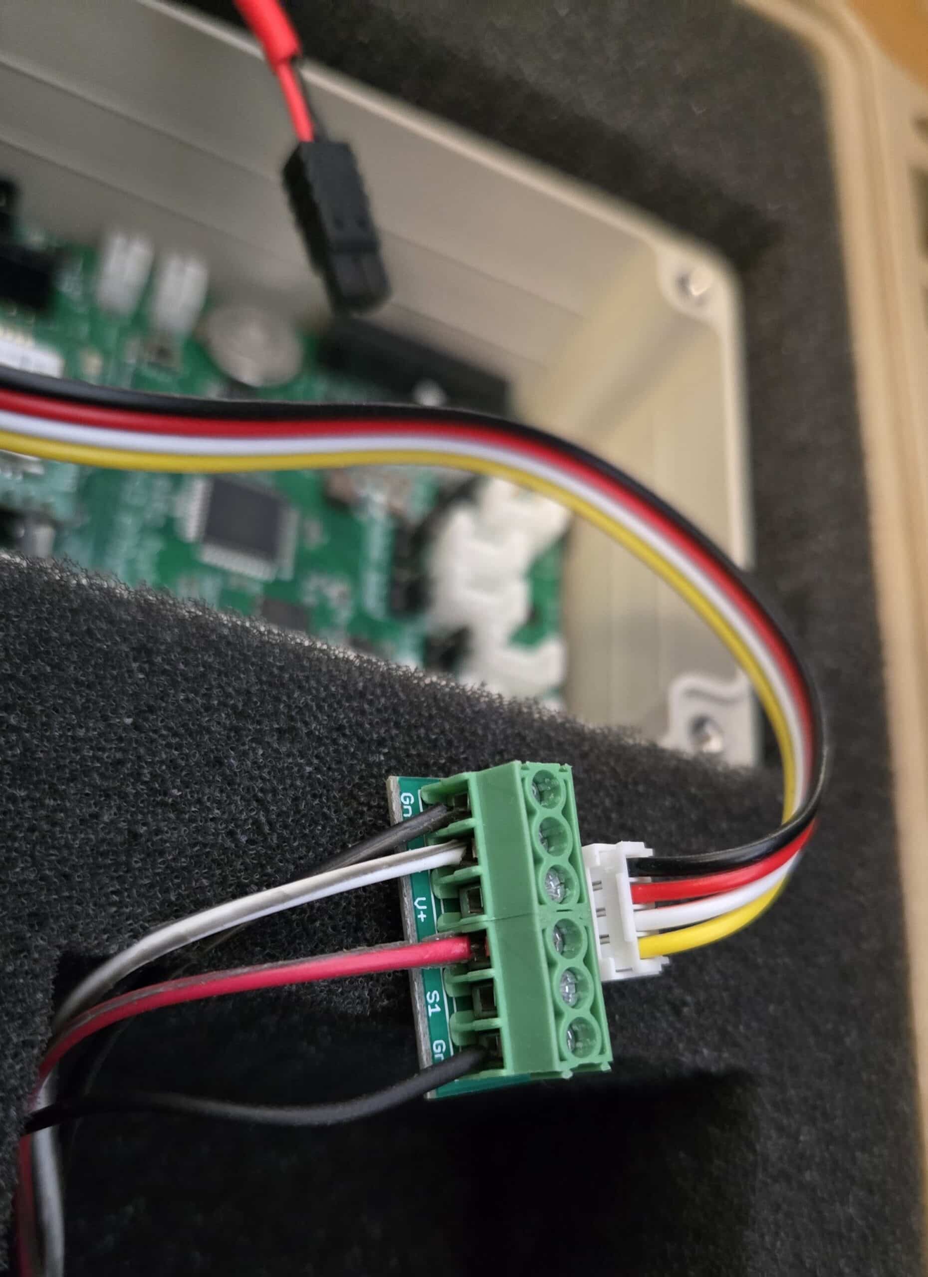
Also, we usually use digital pin D7 in our sketches as the data line for SDI-12 sensors. When you use the 6-pin multipurpose screw terminal as shown in your photo, the data line of the ClariVue turbidity sensor (white) should be connected to the S2 terminal so that it connects to the D7 pin on the Mayfly board (if you use on of the Mayfly’s two Grove jacks labeled SDI12). The S1 terminal of the screw terminal board will connect to the D4 pin of the Mayfly. Or you can change the pin selection solder jumper on the back of the screw terminal board from Default to S1+S2=D2 (there’s photos on the screw terminal shop page showing the different positions). And you must be sure to put the voltage selection jumper next to the Grove jack with the turbidity sensor to the 12v position. The Hydros21 sensor usually works fine at 3v, but sometimes we’ve found that they are more reliable at 5v or 12v, depending on what other sensors are connected to the SDI12 bus.
Attachments:
This thread is for general technical questions about the Mayfly v1.1 board. I don’t know what video you’re referring to, but I assume you’re using an example sketch from our Github repo or that was included with the ModularSensors library that you downloaded. Any example sketch we provide should have a section near the top that says what hardware the sketch is compatible with. Anything written in the past 6 years will be compatible with a Mayfly v1.0 or v1.1 board. If you’re getting an error during compiling, it could be a syntax error or library error. If you already have an existing thread for that issue, please post details in that thread about the specific error message you’re getting and what sketch you’re using.
2025-11-25 at 3:56 PM in reply to: Library alternatives to achieve same goal as dataLogger in Modular Sensors #19443The Sodaq_DS3231 library should work with the current Mayfly boards. Here’s an example from a few years ago that does basic microSD card logging of the onboard sensors and doesn’t rely on ModularSensors: https://github.com/EnviroDIY/EnviroDIY_Mayfly_Logger/blob/master/examples/mayfly1_TempHumidLight_simpleLogger/mayfly1_TempHumidLight_simpleLogger.ino
It sounds like you don’t have all the correct library files installed in your Arduino/libraries folder. How many sub-folders do you have in that directory on your computer? When did you last download the ModularSensors library dependency files?
-
AuthorPosts