
Note: there are two sections on this page: The top half is for the newest Mayfly v1.x boards (released October 2021), and the bottom half is for the original Mayfly v0.5b boards (for boards bought between 2016 and 2020).
Mayfly v1.0 & v1.1
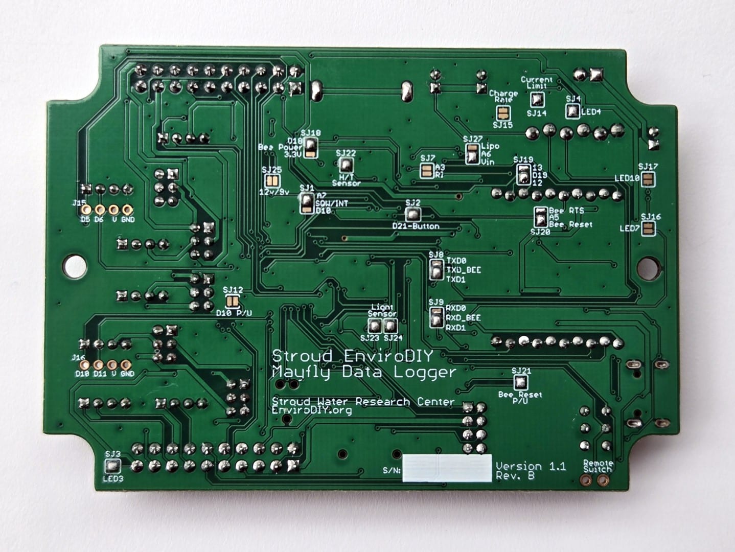
On the back of the Mayfly v1.0 (revA3) there are 20 user-configurable solder jumpers. All solder jumpers on the v1.0 board are now completely made with solder, no cutting of traces between pads is necessary like on older versions.
The Mayfly v1.1 board has 21 user-configurable solder jumpers. All are the same as the v1.0 with the addition of SJ27.
SJ1: Connects the RTC Square-Wave Interrupt line to pin A7 (default) or D10. This allows the RTC to wake up the Mayfly from sleep mode. Default position is connected to A7. Remove the solder bridge to free up pin A7 for something else. Add solder bridge to connect center pad to D10 if you’d like to use the RTC square wave on the D10 hardware interrupt.
SJ2: Connects the user pushbutton to pin D21. Default position is ON. Remove the solder to free up D21.
SJ3: Enables the red LED (LED3) to be lit when the switched power 3.3v/5v/12v lines are turned on. Default position is ON. Remove the solder to disable the LED.
SJ4: Enables the yellow LED (LED4) that is lit whenever the lipo battery is being charged. Default position is ON. Remove the solder to disable the LED.
SJ7: Connects the Bee socket Ring Indicator to A3. Default position is OPEN.
SJ8: Connects the Bee socket TX signal to Mayfly TXD0 (UART 0) or TXD1 (UART 1). Default position is TXD1
SJ9: Connects the Bee socket RX signal to Mayfly RXD0 (UART 0) or RXD1 (UART 1). Default position is RXD1
SJ12: This jumper allows you to easily connect the onboard 1M-ohm pullup resistor to D10. Default position is OFF. Add a solder bridge if you want to connect D10 to the onboard pullup resistor. This is handy for using D10 as a hardware interrupt. DO NOT use this jumper if you have modified SJ1 to use D10 as the RTC interrupt. Also, DO NOT use this jumper if you are using D10 for any other type of input besides something that needs the pullup.
SJ14: Charge/power controller input current limit: 500ma or 1A (default). This jumper allows you to select the maximum current the Mayfly will draw from the USB or battery source. Default setting is 1 amp (solder jumper closed). Remove the solder bridge if you want to decrease the current limit to 500mA. Note that most computer USB ports are limited to providing 500mA so use caution if you leave this in the 1A setting and and attempt to draw more than 500ma from a USB source.
SJ15: Lipo battery charge rate: 500mA (default) or 1A. This jumper allows you to select the maximum charger output current of the onboard Lipo charger. Default setting is 500mA (solder jumper open). Add a solder bridge to increase the rate to 1A. Note that you’ll also need to close jumper SJ14 (set input limit to 1A) in order to get 1A charger output. This setting should only be changed if your input power source can supply more than 500mA. Setting the rate to 1A also causes the bq24074 charger chip to get extremely hot during charging, so use caution.
SJ16: Bee power LED enable. Enables the white LED (LED7) that is lit whenever the Bee power pin is active. Default jumper position is OFF. Add solder to enable the LED.
SJ17: Bee network status LED enable. Enables the blue LED (LED10) that is lit to show Bee module network status (if available). Default jumper position is OFF. Add solder to enable the LED. (only for use with certain Bee modules that offer status output on Bee pin 15, like the Digi Xbee boards)
SJ18: Bee regulator control: D18 (default) or 3.3v. Allows you to control the bee socket power by using D18 (default) or connect to constant 3.3v power.
SJ19: Mayfly pin D19 to Bee pin 12 (default) or 13. This jumper is used to select which Bee board status pin gets connected to Mayfly pin D19. For Digi brand Xbee boards, change this jumper to 13. But for most other modules (like EnviroDIY LTE cell boards), leave this jumper at default pin 12 setting.
SJ20: Mayfly A5 to Bee Reset (default) or Bee RTS. This jumper allows you to select whether Mayfly pin A5 connects to Bee pin 5 for Bee Reset (default) or to Bee pin 16 for Bee RTS.
SJ21: Bee Reset pullup enable. Default position is CLOSED. Remove solder jumper if your bee module needs Bee pin 5 to not be pulled high.
SJ22: SHT40 Humidity/Temp sensor enable. Allows you to remove power from the onboard SHT40 Humidity/Temp sensor. Default position is CLOSED. Remove solder jumper to disable sensor.
SJ23: Analog light sensor enable. Allows you to remove power from the onboard Analog Light Sensor. Default position is CLOSED. Remove solder jumper to disable sensor (also remove SJ24).
SJ24: Analog light sensor to pin A4. This jumper connects the analog light sensor output to Mayfly analog pin A4. Default position is CLOSED. Remove solder jumper to disconnect light sensor and free up pin A4.
SJ25: Boost regulator output voltage selection: 12v (default) or 9v. This jumper allows you to change the output of the usual “Switched 12 volts” output to “Switched 9 volts”. This is useful if you have a sensor that requires 9v but could be damaged by powering it at 12v. Note that all of the Grove jack power jumpers labeled 12v will then be changed to 9v, as well as the 12vSW pins in the 2×10 headers will also become 9v-Switched.
For Mayfly v1.1 (both RevA and RevB):
SJ27: Analog pin A6 connected to either combination Voltage in (default) or direct Lipo battery socket. The default setting works best so that the Mayfly can sense the input voltage of whichever source is highest. With just a Lipo connected, A6 will see the battery voltage (~3.7v). If a solar panel is connected, then A6 will see approximately 4.2v during full sun. If a USB cable is connected, A6 will see 4.9v. If you want to see only the raw Lipo battery voltage independent of the higher voltage from the solar panel, change the solder jumper to Lipo.
For Mayfly v1.1 RevA only:
SJ26: unused. Do not use SJ26 in either setting, leave it open with no solder at all. This feature isn’t used on the Mayfly v1.1 RevA. (It was originally intended to let users select the input source for the 12 boost circuitry, but that feature has been removed and all boards were modified with a small black jumper wire on the top side of the board to hardwire the boost input to the bq24074). DO NOT attempt to solder SJ26 in either position, leave it open with no solder. Clear conformal coating was painted over SJ26 to prevent use. SJ26 was removed from RevB.
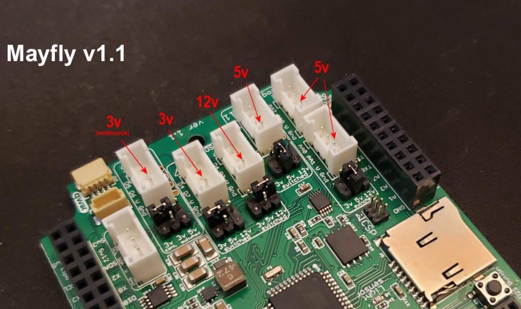
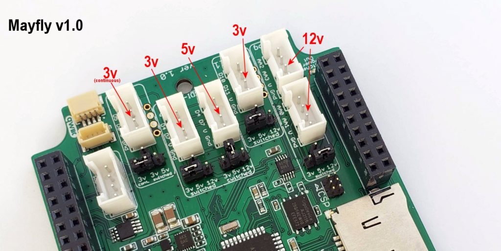
Jumper settings on the Grove jacks on the front of the Mayfly v1.0 and v1.1
On the front of the v1.0 and 1.1 boards, there are 5 small T-shaped pin headers next to the Grove connectors. These headers allow you to select what voltage signal goes on the V line of the Grove connector by putting the little jumper shunt in the proper location.
The one Grove connector labeled “I2C” does not have any voltage setting adjustments via jumpers. The V pin of the I2C jack is constantly powered at 3.3 volts.
The one Grove jack labeled D5-6 can be powered by either 3.3v constantly (default) or the switchable 3.3v or 5v signal (controlled by D22).
The 2 center Grove jacks labeled “D4-7” can be powered by either the switchable 3.3v line (default) or the switchable 5v or 12v line (both controlled by D22). These jacks are also the preferred connections for SDI-12 sensors, hence the SDI-12 label. These jacks have identical signal pins (D4 and D7), but the jumpers allow you to supply 2 different voltages if you’re using two SDI-12 sensors with different power requirements.
The one Grove jack labeled D10-11 can be powered by either switchable 3.3v (default), or 5v or 12v (controlled by D22).
The 2 Grove connectors for the Auxiliary Analog converter can be powered by either the switchable 3.3v line (default) or the switchable 5v or 12v line (both controlled by D22). Both Aux Analog jacks will receive the same voltage as determined by the position of the jumper.
The following photo shows an example of some non-default jumper settings to show how to provide different voltages to the different Grove jacks depending on your sensor needs. Always adjust the jumpers with the Mayfly board turned off, using tweezers or fine-tipped pliers if necessary, making sure not to bend any of the pins. Also make sure the jumper is securely fitted to the header or it could fall off during handling or shipping. These are 2.0mm pitch jumpers so if you lose one, a standard 0.1-inch jumper will not fit securely and could cause intermittent voltage supply to the Grove jack.
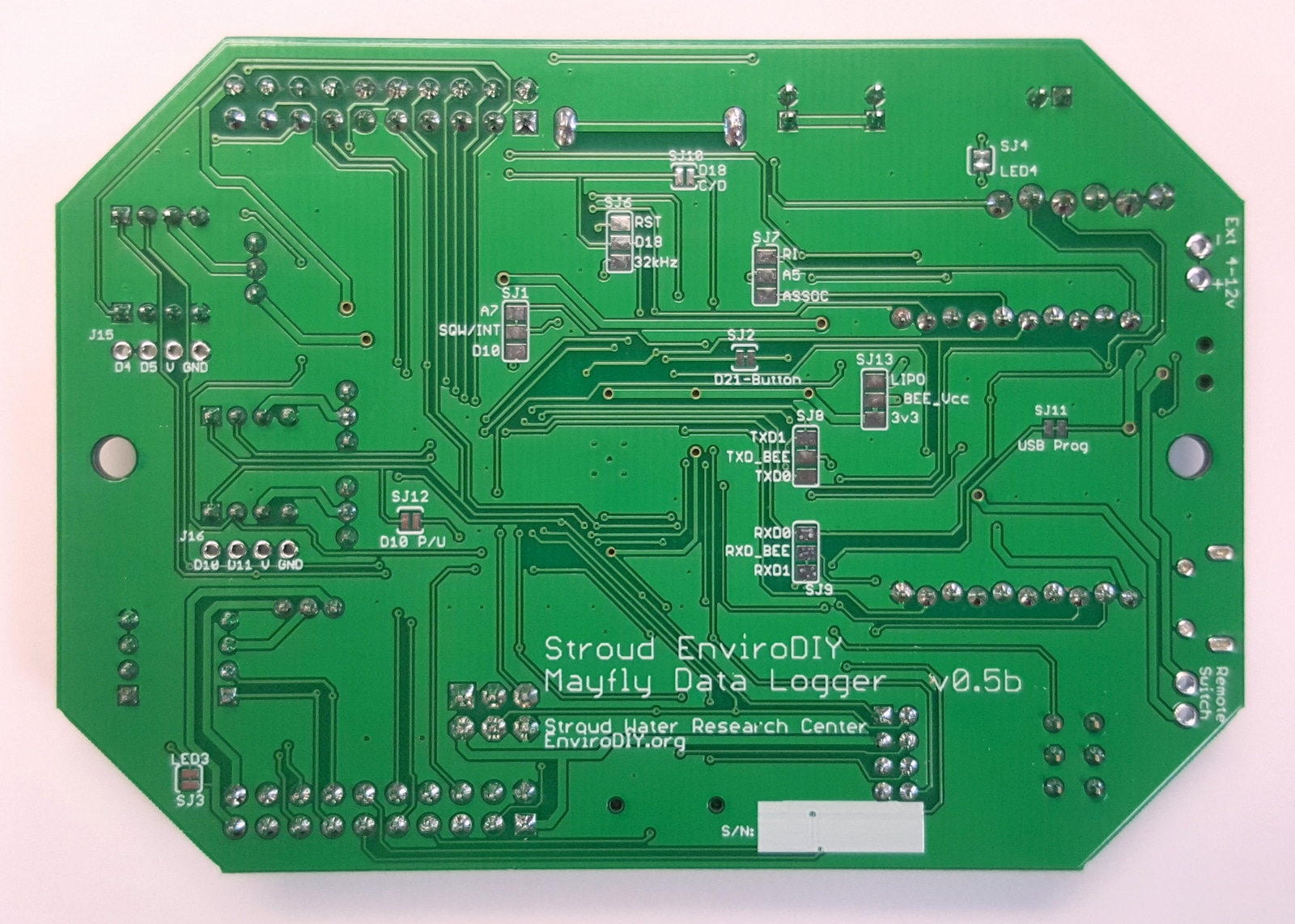
Mayfly v0.5b
On the back of the Mayfly v0.5b board (boards made between 2016 and 2020), there are 12 user-configurable solder jumpers
SJ1: Connects the RTC Square-Wave Interrupt line to pin A7 (or D10 on board v0.4). This allows the RTC to wake up the Mayfly from sleep mode. Default position is connected to A7. Cut the trace to free up pin A7 for something else. Add solder bridge to connect center pad to D10 if you’d like to use the D10 hardware interrupt.
SJ2: Connects the pushbutton to pin D21. Default position is ON. Cut the trace to free up D21.
SJ3: Enables the red LED to be lit when the switched 3.3v line is turned on. Default position is ON. Cut the trace to disable the LED.
SJ4: Enables the yellow LED that is lit whenever the lipo battery is being charged. Default position is ON. Cut the trace to disable the LED.
SJ5: Enables the 5v boost circuitry. Default position is ENABLED. Cut the trace and solder the middle pad to the DISABLE pad to deactivate the 5v boost circuit. Note: This jumper has been removed on board version 0.5 and later
SJ6: Connects the RTC Reset or 32khz signal to pin D18. Default position is NONE. Solder the middle pad to only one other pad if needed.
Note: SJ6 and SJ10 are both used for configuring inputs to D18. Do not use SJ10 if you select a setting for SJ6.
SJ7: Connects the Bee socket Ring Indicator or Associate lines to A5. Default position is NONE.
SJ8: Connects the Bee socket TX signal to Mayfly TXD0 (UART 0) or TXD1 (UART 1). Default position is TXD1
SJ9: Connects the Bee socket RX signal to Mayfly RXD0 (UART 0) or RXD1 (UART 1). Default position is RXD1
SJ10: Connects the microSD socket’s Card Detect line to D18. Default position is OFF. Solder this jumper together if you want to be able to sense a memory card in either the horizontal socket or the vertical adapter board.
Note: SJ6 and SJ10 are both used for configuring inputs to D18. Do not use SJ6 if you select a setting for SJ10.
SJ11: Controls power to the FT232RL USB chip. Default position is ON. Cut this trace if you do not want to use the USB port for programming.
SJ12: Only on board v0.5 and later, this jumper allows you to easily connect the onboard 1M-ohm pullup resistor to D10. Default position is OFF. Add a solder bridge if you want to connect D10 to the onboard pullup resistor. This is handy for using D10 as a hardware interrupt. DO NOT use this jumper if you have modified SJ1 to use D10 as the RTC interrupt. Also, DO NOT use this jumper if you are using D10 for any other type of input besides something that needs the pullup.
SJ13: Only on board v0.5b and later, this jumper allows you to select the power source for the Bee socket’s Vcc pin (Bee pin 1). The default setting is that Bee is powered by the Mayfly’s main 3.3v Vcc supply. By cutting the SJ13 trace and soldering the middle pad to the LiPo setting, you can connect the Bee Vcc pin directly to the Mayfly’s LiPo battery input.
On the front of the board, there are 4 small 3-pin headers next to the Grove connectors. These headers allow you to select what voltage signal goes on the V line of the Grove connector.
The 2 Grove connectors labeled “I2C” and “D4-5” can be powered by either 3.3v constantly or the switchable 3.3v signal (controlled by D22).
The 2 Grove connectors labeled “D6-7” and “D10-11” can be powered by either the switchable 3.3v line or the switchable 5v line (both controlled by D22)
The 2 Grove connectors for the Auxiliary Analog converter can be powered by either the switchable 3.3v line or the switchable 5v line (both controlled by D22)
These are 2.0mm pitch jumpers, so a standard 0.1-inch jumper will not fit securely.