
 Welcome to EnviroDIY, a community for do-it-yourself environmental science and monitoring. EnviroDIY is part of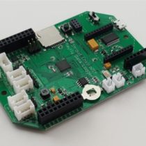
@shicks
Active 1 day, 6 hours agoForum Replies Created
-
AuthorPosts
-
I’m not sure what you mean by “The page says 12V is the default” because the default Grove jack jumper setting of the Mayfly v1.1 boards has always been 3.3v. You have to manually move a jumper if you want to select 5v or 12v for the Grove jacks on the Mayfly v1.1 board. So verify that the jumper next to the Grove jack you’re using for the sensor is set to 12v. It would also be good to use a voltmeter (also known as a multimeter) to measure the voltage you’re applying to the sensor to verify that the voltage is really 12v and isn’t sagging during the motor movement or sensor sampling. It could be that the motor is drawing more current than the Mayfly can supply. The user manual for the DTS-12 says it can draw up to 200mA during wiping, which is right around the upper limit of what the Mayfly v1.1 can supply at 12v. So if you watch the output voltage of the Mayfly with a voltmeter during the wiping action, you should be able to see if it stays near 12v or if it drops. The sensor manual also mentions that the SDI12 sampling commands are different depending on which firmware the sensor has, so you might want to check with the manufacturer to find out what version your sensor is operating with. Have you successfully used that sensor with other dataloggers besides Mayfly boards? You could also try powering the sensor directly from an external 12v battery and only using the data (and ground) lines from the Mayfly to handle the communication. (be sure to connect the ground of the Mayfly board to the ground of the external battery so they’re both using the same ground reference). Then verify that you’re sending the proper sample and measurement report commands according to the tables in the user manual appendix.
There are instructions on the Grove jack jumper settings on this page, including a photo showing examples of what the jumper position would look like for the different options: https://www.envirodiy.org/mayfly/hardware/jumper-settings/
What is the board version of the Mayfly data logger board that you’re using? Did you set the jumper header next to the Grove jack to the 12v jumper setting? Are you using the latest version of the EnviroDIY_SDI12 library?
I’d suggest trying a product called Goo Gone. It’s a citrus-based adhesive/sap remover that is safe for use on plastic. DO NOT use Goof Off, it isn’t safe for plastics and will damage the solar panel. Rub a little Goo Gone on the sap and let it sit for a few minutes, then wipe it off and rinse it off with some soap and water. It might take a couple tries, but it should take care of it.
Yes, absolutely—we’d love for you to share it! One of the best things about the EnviroDIY community is seeing the creative ways people adapt the Mayfly and develop new hardware and software solutions for their monitoring needs.
A post describing your LoRa implementation would be very helpful, especially since this is something we haven’t documented yet. Please feel free to include as much detail as you’re comfortable sharing, such as the LoRa board you used, wiring or connection details, code, photos, and anything you learned along the way.
We strongly encourage everyone in the community to share their projects, modifications, and new ideas. Even if a solution is still a work in progress, it may inspire someone else or help another user working on a similar application.
The shield wire of the OBS3 sensor cable doesn’t actually connect to anything on the sensor, so it’s okay to leave that floating, especially if you’re just testing the sensor. The green and black wires both definitely need to be connected to GND or the sensor won’t work properly. Both the high range and low range should read around 0 NTU when the sensor is in air (assuming the sensor is clean and not pointing at any objects). You should also not test it near sunlight (out of the water) because the light from the sun will interfere with the sensor’s IR input and you’ll get extremely inaccurate results. Placing a dark object like a towel or a boot or a glove over the sensor will give inconsistent results since the IR reflectivity of different color objects will give different readings. We found that using a piece of white paper or a bare hand about an inch away from the sensor is a good way to see if you get full-scale readings from the two sensor outputs. Using a voltmeter, you should see around 2.5v for both sensor output wires when you do this. With nothing near the sensor, you should see very close to 0v on both channels. (Be sure to check that you’re getting 5v from the Mayfly on the V+ line of the screw terminal too).
It’s possible to use a battery that big, as long as the polarization of the JST connector is the same. However, we rarely have the need for a large battery with our standard stations with sensors like CTD, turbidity, or oxygen, even with cellular telemetry ever 5 minutes. If you use a really large battery, you have to make sure your solar panel is appropriately sized to fully charge the battery on most sunny days. If your sensors are drawing a lot of power and your solar panel is undersized (or in a lot of shade), then you might have trouble fully charging a giant battery every day and you’ll end up with a dead battery after awhile. If you have a really power-hungry sensor or accessory that draws high amounts of current, it is usually a 12-volt sensor or motor or pump, so it would make more sense to use a 12v battery in your enclosure, along with a 12v solar panel and a separate 12v charger for whatever type of battery chemistry your 12v battery is. The Mayfly logger boards were designed to run on 3.7v lipo batteries, and there are boost converter that generate the switched 5v and 12v supplies for external sensors. The latest Mayfly v1.1 boards use power directly from the solar panel input connector to power the logger and boost converters, and will only draw power from the battery if there’s not sufficient power from the solar panel. This means that on sunny days, many stations with simple sensors and a cell board can operate totally from sunlight for a large part of the day, and only draw power from the battery at night, or when it’s cloudy. This is an improvement over previous Mayfly designs from earlier models where all power is supplied from the battery at all times and it only charges when there’s sufficient light. This means that stations are more efficient with how they use power. We also started using the ETFE solar panels a few years ago that offer 5watts out output power, instead of the 3.5watts the older style panels produced with the same size. So for most people, the new panels coupled with the newest version of the Mayfly board result in sufficient charging and power supply for most deployment configurations.
Those old Campbell OBS3+ turbidity sensors will either flatline or go negative when they fail. We started deploying dozens of that sensor model about 8 or 9 years ago and almost all of them have been removed from the field in the past few years due to failure. It looks like your station is 8 years old so you got more life out of it than most. To double-check that the sensor really is bad, you can put the Mayfly logger into continuous testing mode by pressing the D21 button, so that the sensors stay powered continuously for a few minutes. Use a voltmeter to check the 5v output supply voltage of the Mayfly board, using the Vcc and Gnd pins of the screw terminal board that the turbidity sensor is connected to. You should see around 5v when the sensor is being powered. If not, your Mayfly board isn’t generating the 5v signal to power the sensor, or the sensor is drawing too much power (usually due to flooding of the sensor housing) so it is shorting out and causing a voltage sag on the supply. You can also check the signal output voltage of the sensor by looking at the two sensor signal wires on the screw terminal board (test them individually, so measure across S1 and Gnd, then S2 and Gnd.) Because I built and installed that particular station you’re referring to, I still have the voltage-to-NTU conversion calibration sheet from the manufacturer so I can send you the equations the logger uses to convert the raw analog voltage readings to NTU. If you manually calculate the turbidity different than what the Mayfly is calculating, then it could possibly be the analog-to-digital converted on your logger board has gone bad, but this is rare. It’s more likely that the sensor has simply died, but since Campbell doesn’t repair these anymore, you only option would be to replace it with something like the newer ClariVue turbidity sensor.
We’re really excited to partner with Labcrafter so they can be a source of our products to people in Europe. As for sensors, the Maxbotix MB7389 you mentioned is probably your best bet for low cost ultrasonic rangefinding. Just be sure to order the TTL version so it’ll work straight into the Mayfly board (the RS232 sensor would require an interface chip). I haven’t used the Atlas Scientific pH sensors so I don’t have any advice on them.
All Mayfly logger board from version 0.3 to the current v1.1 (and including your v0.5v) have a separate 3.3v regulator that powers external sensors, and also the 5v boost circuit. This secondary 3.3v regulator is turned on or off by controlling pin D22. When the regulator is turned on, a red LED in the lower left corner of the Mayfly should turn on. There’s a possibility that perhaps the sensor died and damaged the 3v (or 5v) output circuitry on your Mayfly. Do you see the red LED (labeled LED3 on the Mayfly v0.5b) turning on during samples? Have you tried putting a voltmeter across the ground (GND) and V pins of the SDI12 grove jack during readings to see what voltage you’re sending to the sensor? You can set the voltage selection jumpers to either 3.3v or 5v for the Hydros21 sensor, it should work with either.
How old is the sketch that you’re using on the v0.5b board? If your old board was programmed before May 2022, then the old code won’t work with the newer Gen2 Hydros21 sensors because the SDI12 library for communication with the library had to be adjusted for some slight timing changes in how the Mayfly communicates with the sensors. Your v1.1 board is newer and probably has the updated SDI12 library and therefore is able to successfully talk to the sensor.
-
AuthorPosts