
6.1 Assembling the Mayfly Data Logger Electronics
View the EnviroDIY Monitoring Station Parts List
To build an EnviroDIY Monitoring Station, first start by preparing the electronic components of the station.
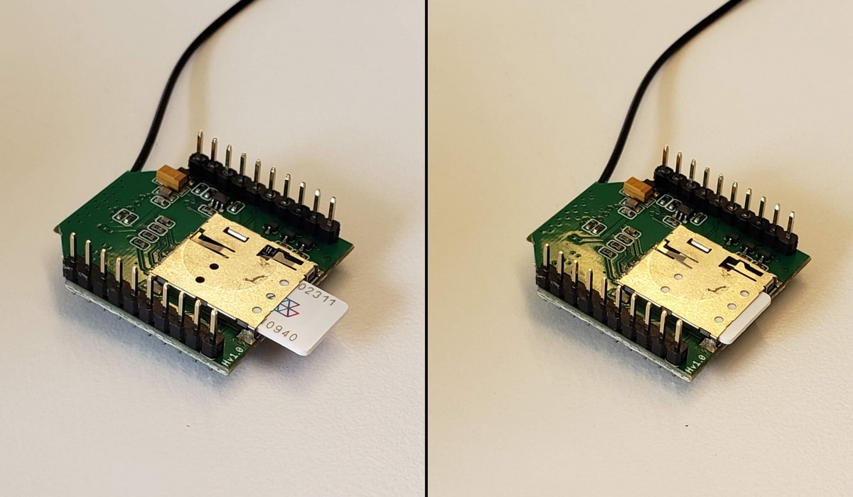
- Insert the cellular SIM card into the slot on the bottom of the cellular radio module board (we recommend the Global SIM cards from Hologram.)
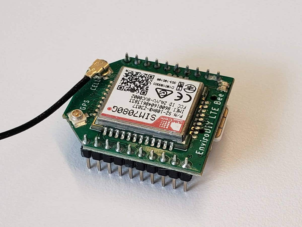
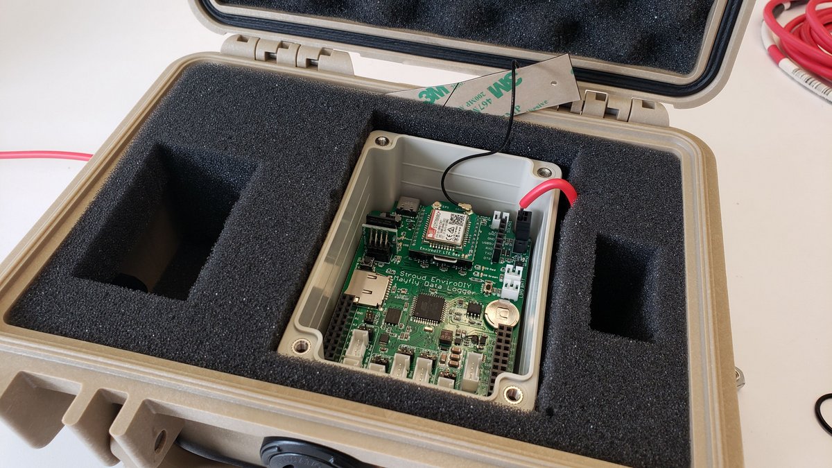
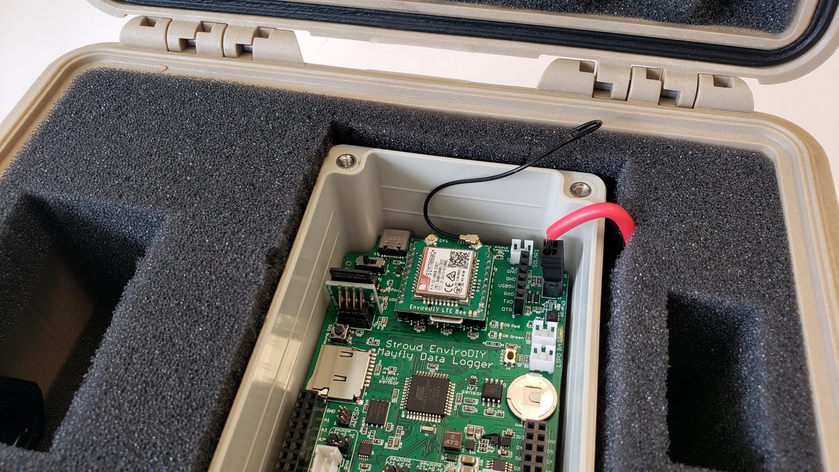
- Plug the cellular module into the Mayfly Data Logger’s Bee port in the orientation shown in the photos, making sure to get the pins lined up correctly.
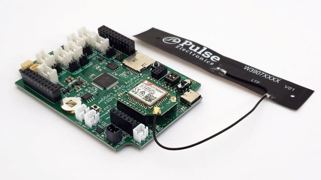
- Connect the cellular antenna to the appropriate jack on the cell module (labeled CELL). There is a GPS antenna jack on the board if you want to utilize the GNSS(GPS) functionality of the SIM7080, but it is not typically used in the EnviroDIY Monitoring Stations, so you can leave the GPS jack unconnected. It is easier to attach the cell antenna to the Bee module once it’s mounted onto the Mayfly board. We recommend the flexible Pulse brand 4G LTE cellular antenna with U.FL connector (available at vendors like Digi-Key)
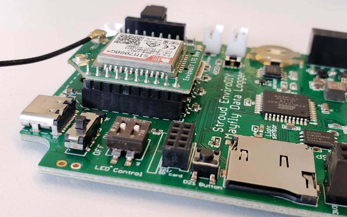
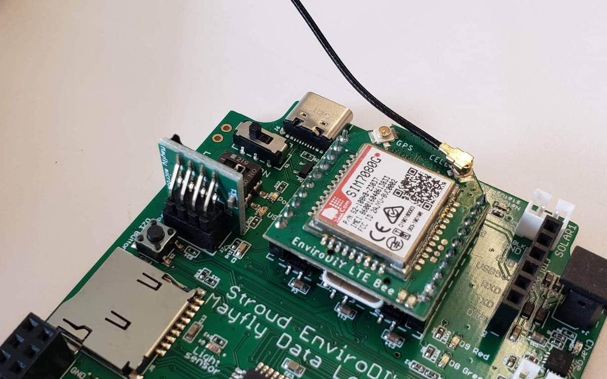
Plug the vertical microSD card adapter board into the small 2×4 SPI header socket on the Mayfly Data Logger (near the main power switch). Take care not to bend the adapter sideways after installation or the pins will break off. The vertical microSD card socket provides the exact same function as the onboard microSD card socket on the Mayfly, but it makes accessing the card much easier when installed in the case. You can only use one microSD card at a time, so do not insert a card into both sockets. If you do not have a vertical card adapter or do not wish to use one with your installation, the onboard card socket can be used and there are no changes you need to make to the Arduino code.
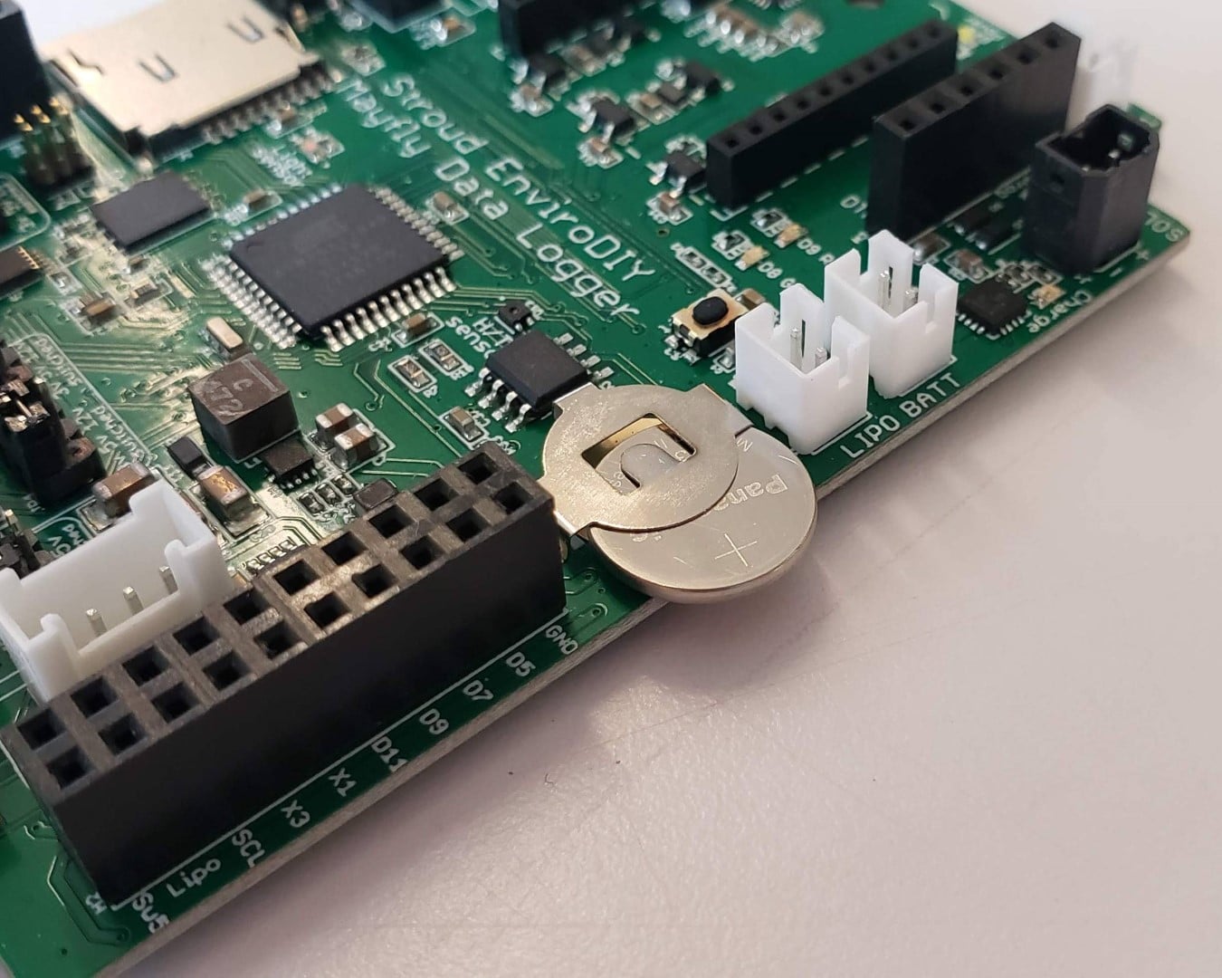
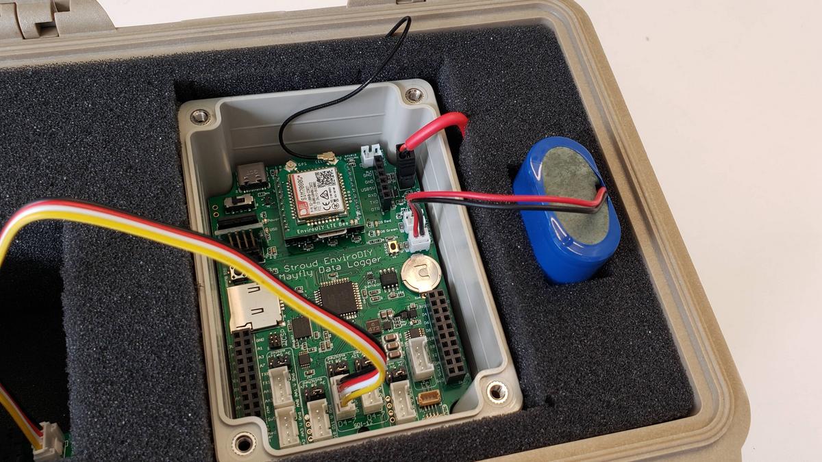
Insert the CR1220 lithium coin cell battery if not already done in the previous sections. This is the backup battery for the Mayfly’s clock chip so that it will retain the clock time after programming, even if the main battery is disconnected. Note that the + side faces up.
You don’t need to connect an external main battery to the Mayfly until the end of assembly, but if you decide to test the Mayfly board before assembling the Pelican case, the following information about the lithium battery packs is extremely important.
Recommend battery pack: Lithium Ion Battery Pack – 3.7 V 4400 mAh: This lithium ion pack is made of two balanced 2200 mAh cells for a total of 4400 mA capacity. Vendor link: Adafruit or Digi-Key
Insert the Lithium Ion Battery Pack JST connector into only one of the two connectors on the Mayfly labeled LIPO BATT. Do not connect 2 battery packs to the Mayfly at the same time.
Important! Not all Lithium battery packs with JST connectors have the correct polarity. Battery packs from Adafruit and Sparkfun that have the JST connectors will have the correct polarity, but other vendors sometimes have packs with reversed-polarity jacks, which results in catastrophic damage to the Mayfly board if connected. Verify before connecting your battery pack to your board that the red wire will go to the pin labeled “+” and the black wire will go to the pin labeled “-” as shown in the photo.

For more information about battery options, see EnviroDIY Data Logger Battery Options.
6.2 Pelican Case Assembly
View the EnviroDIY Monitoring Station Parts List
The waterproof logger box contains the circuitry of the EnviroDIY Monitoring Station. Pelican 1120 cases are the smallest opaque cases from Pelican that also have holes for securing the lid with a padlock, so that’s the recommended case. They can be purchased in various colors, but tan or silver usually work best for blending into most environments. They can also be purchased with or without the foam inserts, but having the foam makes it simpler to holding the Mayfly and accessories inside the case, so choose the foam option if buying the case from a retailer. Cases sold through the EnviroDIY Shop contain the foam which is already pre-cut for holding the Mayfly and battery. The foam can be cut easily with a sharp hobby knife.
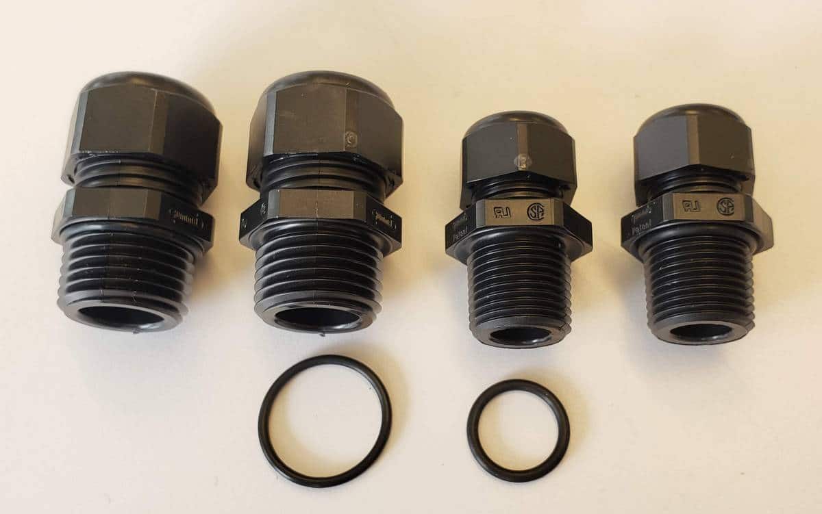
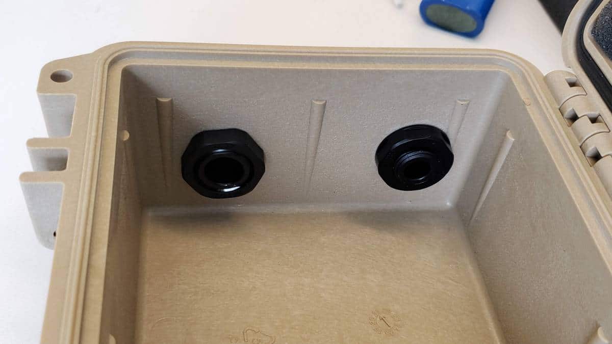
Cable glands are needed for routing the sensor cables into the Pelican case.
- For a CTD sensor: mcmaster.com item 69915K53.
- For the solar panel cable: mcmaster.com item 69915K52.
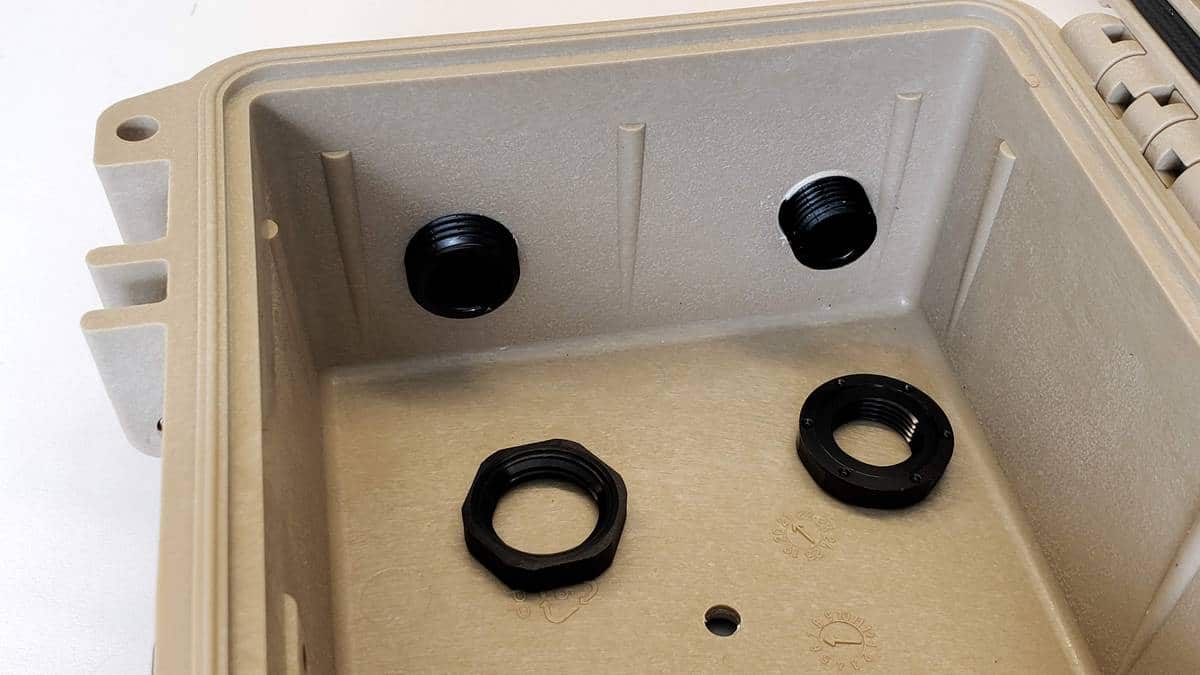
Monitoring Station Kits purchased from the EnviroDIY Shop will have the two cable gland holes already drilled and tapped. If drilling the holes yourself, you will need two large drill bits and two NPT taps. For the smaller cable gland (for the solar panel wire), drill a hole with a 37/64” bit and tap it with a 3/8″ NPT tap. For the larger cable gland for the CTD sensor, drill a 23/32” hole and tap it with a 1/2″ NPT tap. Install the small rubber o-rings that came in the cable gland package onto the threaded ends of the cable glands, making sure they are flush up against the center hex portion of the cable gland before proceeding. Screw the cable glands into the case from the outside and tighten them using an adjustable wrench, but not too tight that the threads get stripped. Thread the large plastic backing nuts onto the cable glands from inside the case and use a socket wrench and sockets (15/16” and 1-1/16”) to tighten the nuts gently.


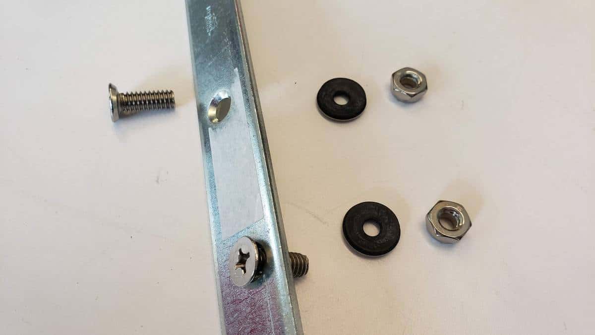
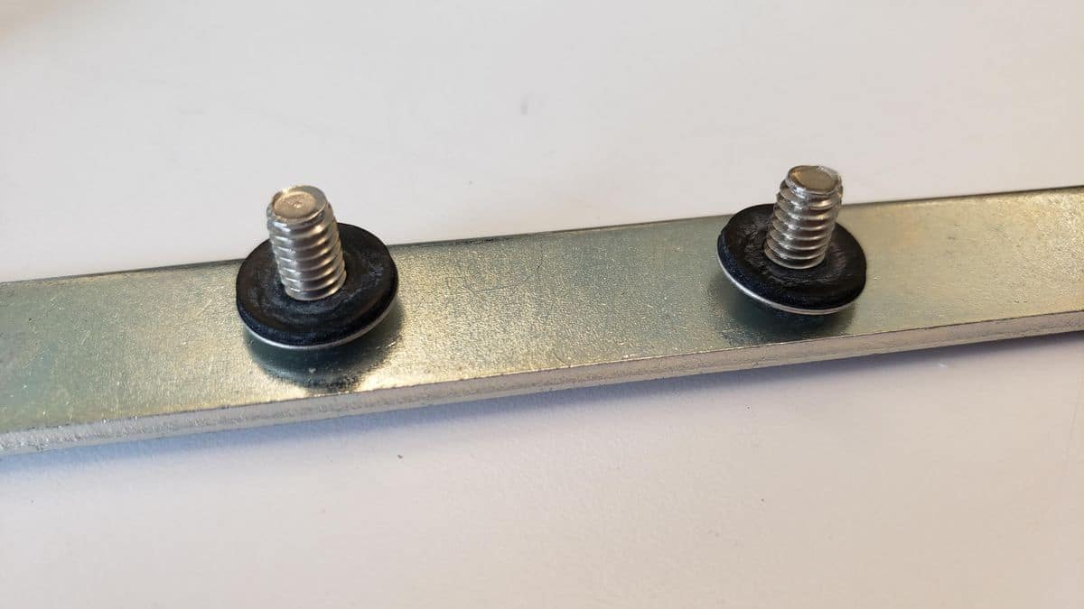
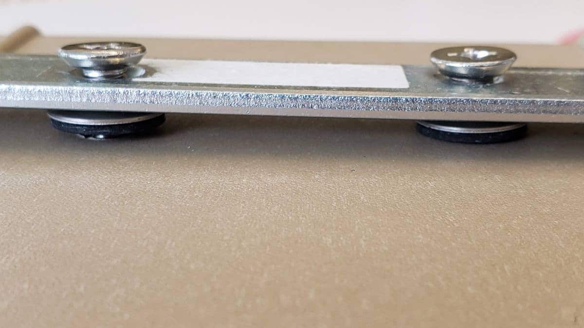
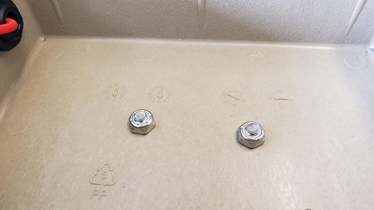
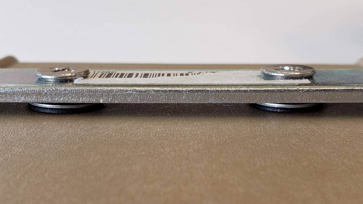
You will also need to drill two 1/4″ holes in the back of the case for the mending plate mounting bracket if you don’t have a kit from the Shop. Use the mending plate to mark the holes on the back of the case, keeping the countersunk part of the mending plate facing away from the case. Then install the bracket on the back of the Pelican case using the 1/4″ stainless steel mounting hardware as shown in the following photos. Be sure to put the neoprene-backed sealing washers in the correct orientation so that they provide the proper protection from water entering the case. Use nylon lock nuts on the inside of the case and tighten everything securely so that the washer flattens out slightly as shown in the last photo, indicating that a proper tight seal has been formed.
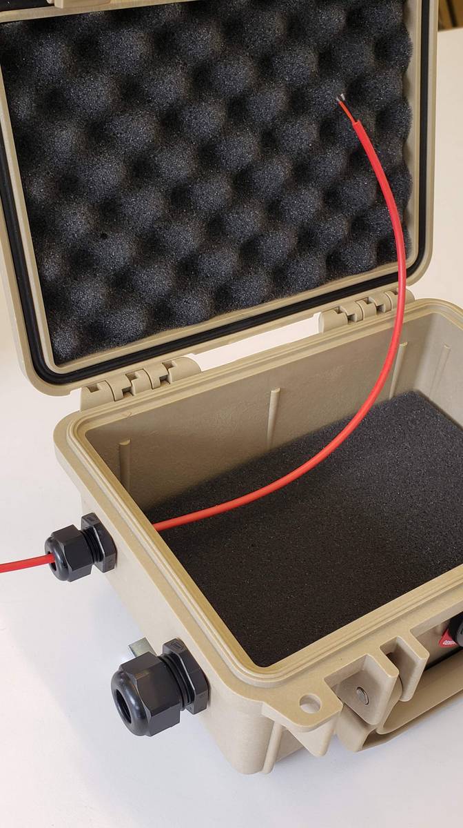
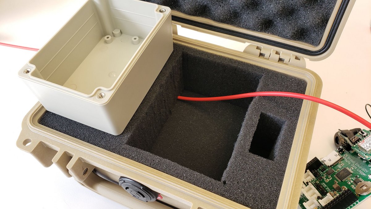
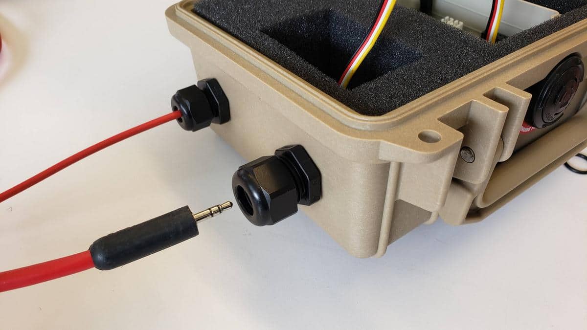
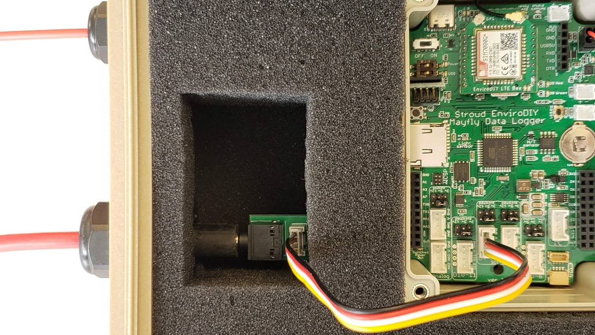
Next it’s time to route the solar panel cable into the Pelican case. Insert the thin smooth piece of foam into the bottom of the pelican case. With the large center section of foam still outside the case, insert the bare-wire end of red solar cable into the small cable gland from the outside and route it up towards the top of the case where the Mayfly box will be. Insert the center foam section and pull the solar cable up through the large hole in the foam where the Mayfly will be mounted. Don’t tighten the solar wire cable gland yet until everything is assembled and the Mayfly is installed in the case and you’ve adjusted the length of the cable inside the case. When you do finally tighten the cable in the cable glands later, only use your hands to obtain their final snugness, do not use tools to tighten the cable glands against the cables.

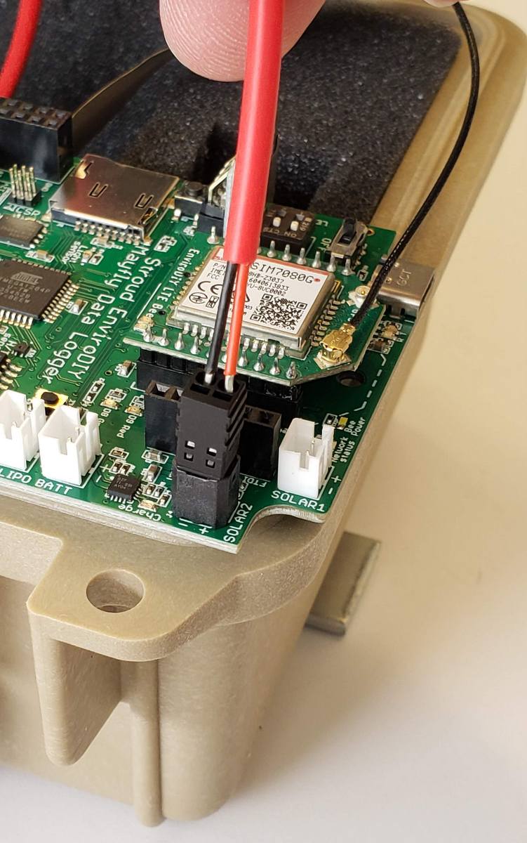
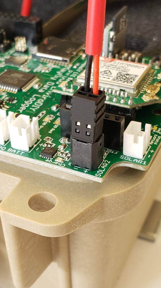
Now it’s time to connect the quick-connect plug to the end of the solar cable. Remove the small black protective cap that was on the black SOLAR jack in the upper corner of the Mayfly board (if applicable, on certain v1.0 and v.1.1 boards only). Insert the black quick-connect plug that was included in the Monitoring Station Kit. If you didn’t purchase a kit, these plugs can be bought from vendors like Digikey. Note the proper orientation of the red (+) and black(-) wires in the photos below. (Some solar cables contain red and white wires, instead of red and black. Red is always positive, and either black or white is negative). Gently insert both bare wires into the round holes of the plug as shown. Once the bare portion of the wires have been inserted all the way down, small springs inside the plug will securely hold them and keep them from pulling out. Very gently pull on the wires to make sure they are secure. If for some reason you later need to remove the wires, you’ll need to insert a very sharp tool (like tweezers or flat-blade micro screwdriver) into the rectangular slot next to the wire holes in order to release the spring.
If you do not have a black quick-connect socket on your Mayfly board, you will need to use the white JST-style solar panel socket instead. If you solder your own JST connector onto the solar wire, be sure to observe the polarity of the solar jack, since many JST connectors that are purchased from various vendors have the incorrect polarity.
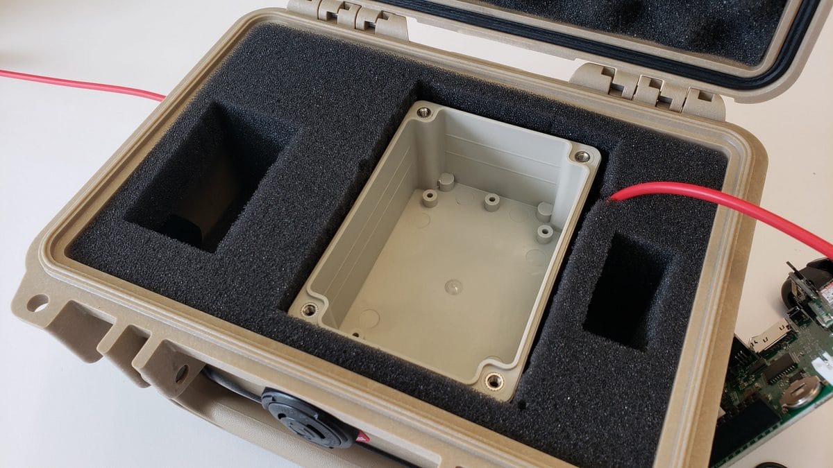
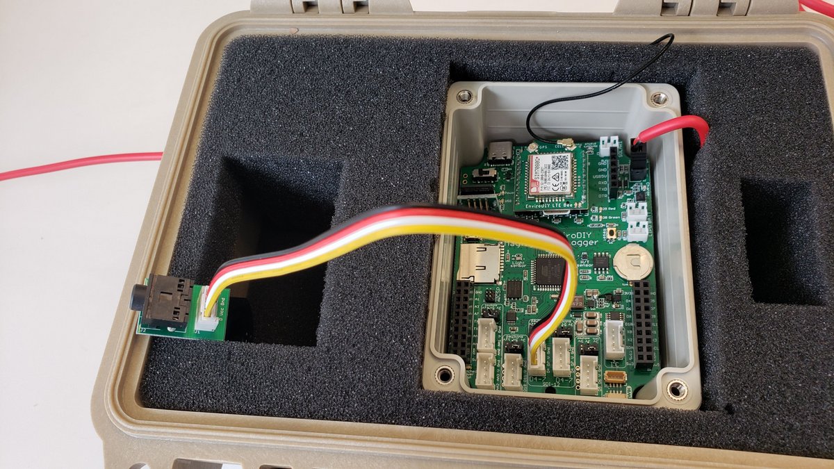
Put the small plastic enclosure (Hammond RP1095 case) into the large hole in the middle of the foam, making sure to pull the solar cable up through the top of the hole as shown in the photo. You won’t need the Hammond enclosure’s lid when the case is being mounted inside the Pelican box, so you can put the small case’s lid aside. Put the Mayfly Data Logger board down into the small case in the orientation shown in the photo and connect the solar panel cable to the jack labeled “SOLAR” on the Mayfly Data Logger.
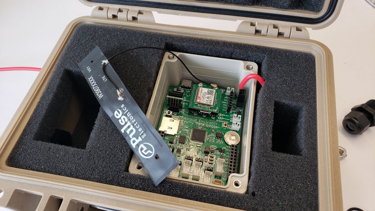
The flexible cellular antenna needs to be tucked out of the way so it doesn’t get damaged, so the easiest place to put it is between the foam and the side of the Pelican case, as shown in the following photos.
Put the LiPo battery in the battery slot in the foam at the top of the case and connect it to either one of the two jacks labeled “LiPo Batt” on the Mayfly Data Logger. Important: DO NOT connect more than one Lipo battery to the Mayfly at the same time. Make sure the battery’s connector has the correct polarity as explained above or catastrophic damage to the Mayfly will occur.
6.3 Connecting Sensors to the Mayfly Data Logger
View the EnviroDIY Monitoring Station Parts List
The Hyrdos 21 CTD sensor cable can be with ordered bare wires (default) or with a 3.5 mm stereo plug (preferred option). In order to connect the stereo plug to the Mayfly, a Grove cable and Stereo Plug Adapter board are needed. These are included in the Monitoring Station Kit, or can be purchase separately.
Insert the CTD sensor plug into the Pelican case’s large cable gland a few inches and hand-tighten the gland, making sure the gland is tightened around the cable and not the molded part of the plug. Use the EnviroDIY Grove-to-stereo adapter board to connect the CTD sensor to the Mayfly using a 20 cm Grove cable between the adapter board and the Mayfly board. On Mayfly board v1.0 and 1.1, the CTD should be connected to either of the SDI-12 grove jacks (the two middle Grove jacks labeled D4-7 and SDI-12). On Mayfly v0.5b, connect the CTD to the D6-7 Grove jack.
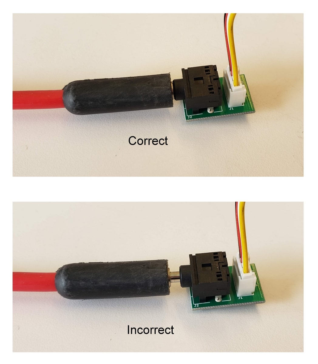
Make sure you insert the stereo plug fully into the jack. If at any time the Mayfly can’t communicate with the Hydros21 sensor, check that this connector is installed correctly.
The CTD sensor will also require a programming step before it is compatible with the Mayfly’s recommended logging sketch. The default SDI-12 address for the Hydros 21 CTD sensor is “0”. This needs to be changed to “1” in order for the Mayfly Data Logger to correctly communicate with the sensor. Use the “SDI-12 Change Address” sketch from the SDI-12 Arduino library to change the sensor address from 0 to 1. Follow the directions on that Github page to change the sensor channel number.
Alternatively, you could purchase a ZSC Sensor Interface from Meter Group, which is a handy little bluetooth device that allows you to use an app on your phone to test and program Meter Group sensors.
6.4 Mounting Parts and Solar Panel Attachment
View the EnviroDIY Monitoring Station Parts List
Mounting parts (Table 6.4.1) include all items that will keep the EnviroDIY Monitoring Station in a fixed position on the stream bank. To ensure that the EnviroDIY Monitoring Station properly functions long term in outdoor conditions, the logger box is typically mounted on a tall pipe to keep it out of harm’s way during high flow conditions. The length of the pipe can vary based on the specific features of a site (Figures 6.4.1 and 6.4.2). Mounting materials that will be installed on land include the galvanized pipe, ¾” coupling, small hose clamps, solar panel bracket, and U-bolt. In addition to the mounting bracket, two small stainless steel hose clamps (range: 13/16” to 1 ½”), are needed to attach the logger box to the galvanized pipe (Figures 6.4.3 and 6.4.4).
The location of the monitoring station depicts what size solar panel will be used. If the station is located in a open sunny field, a 2-watt solar panel will sometimes be sufficient. If the station is located in an area with moderate vegetation a 5-watt ETFE solar panel should be used (this is the solar panel size most commonly used and will be sufficient in most cases). If the monitoring station is located in extremely dense vegetation for most of the year (i.e abundant evergreen vegetation) a larger 10-watt solar panel is available.
- 6V 5W ETFE solar panel: this is the new default panel we recommend with stations since it is more efficient for the same size as the older style panel.
- Solar Panel Mounting bracket: universal bracket that can mount various Voltaic Systems panels to a pole.
- Mounting feet for ETFE panels (included in station kit)
- Extension cable: for connecting panel to Mayfly Logger (included in station kit)
- 6V 2W Solar panel (optional): Optional 2-watt smaller solar panel for locations with unobstructed sunlight.
- 6V 10W Solar panel (optional): Optional 10-watt large solar panel for locations with excess shade or high power draw from sensors.
The solar panels from Voltaic Systems are waterproof, scratchproof, and rugged enough to withstand long-term outdoor deployment. The three different sized solar panels can all be attached to the galvanized pipe using the same solar panel bracket also available through Voltaic Systems. The solar panel is attached to the bracket using two screw-and-washer mounting feet, which can be tightened and secured using a small Phillips-head screwdriver.
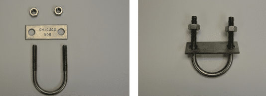
Once the solar panel is attached to the bracket, a stainless steel U-bolt is then used to attach the bracket to the galvanized pipe above the logger box (Figure 6.4.7). The nuts associated with the U-bolt can be tightened using a 7/16” size wrench. Be sure not to over-tighten the U-bolt because the flat plate on the U-bolt is made from aluminum and will bend if tightened too much.
Table 6.4.1. Mounting parts for EnviroDIY Monitoring Station.
| Item name | Vendor | Item number | Description |
| ¾” coupling | Lowe’s Home Improvement | 22481- (black) 22310- (silver) | Used to secure the two different sized galvanized pipes together. Available in black or silver to match color of pipes. |
| Galvanized pipe (also available in black) | Lowe’s Home Improvement | ¾” x 36” galvanized pipe – 24012 ¾” x 60” galvanized pipe- 24072 | A variety of sizes are available for specific station needs. Provided here, are the two sizes most commonly used. These pipes will be installed on the stream bank. |
| Small hose clamps (x2) | Lowe’s Home Improvement | 910974 | Used to mount the EnviroDIY Data Logger box to the galvanized pipe |
| Universal Solar panel bracket | Voltaic Systems | bracket | Compatible with a 2, 3.5, and 9 W solar panel. Used to mount the solar panel to the galvanized pipe |
| Stainless steel U-Bolt with mounting plate | McMaster- Carr | 8896T94 | Used to mount the solar panel and bracket to the galvanized pipe. |
| Black rebar (with predrilled holes) | Lowe’s Home Improvement | 44086 | The outside diameter of this rebar is the perfect size to fit inside of the PVC pipe. This will be hammered directly into the stream bed to mount the sensor bundle. |
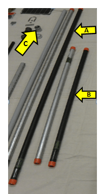
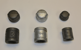
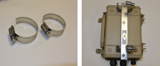
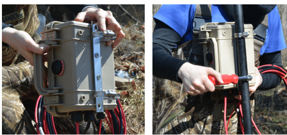
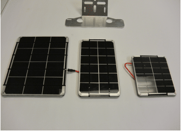
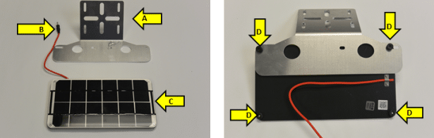
Figure 6.4.6 A. Voltaic Systems universal solar panel bracket. Attach a Voltaic solar panel to any vertical or horizontal pole or vertical pipe. Rugged 3 mm aluminum is built to withstand high winds and rough conditions. The bracket is compatible with their 2, 3.5, 6 and 9W solar panels.
Figure 6.4.6 B. Waterproof solar panel wire. This solar panel wire will not plug directly into the Mayfly Data Logger. There is also a 4’ extension wire available through Voltaic Systems for $6 if the solar panel needs to be mounted higher up on the galvanized pipe. This is the case in most scenarios.
Figure 6.4.6 C. 3.5W Voltaic Systems solar panel. The 3.5W 6V solar panel is lightweight, waterproof, and designed for long-term outdoor use in any environment. The panel uses high-efficiency monocrystalline solar cells, and is UV- and scratch-resistant.
Figure 6.4.6 D. Location to attach solar panel to bracket. These knobs can be unscrewed using your fingers or a small flat head screwdriver. Simply unscrew, place the threads through the openings on the solar panel bracket and tighten.
6.5 Sensor Bundle Parts
The sensor bundle is comprised of the two different sensors (CTD and turbidity), a drilled PVC pipe, black rebar with holes and a spiked end, a large (2 ½”) stainless steel hose clamp, a retaining pin, and black outdoor use zip ties (Table 6.5.1, Figure 6.5.1). These materials will be anchored into the bottom of the stream bed once the black rebar is hammered into the substrate. The rebar must be anchored into the stream bed deep enough so that it will not become dislodged under high flow conditions.
Using a power drill and two different sized drill bits (5/32” and 3/16”), make a hole 1 ½” from the top of the PVC pipe that lines up with the hole pre-drilled in the black rebar. The retaining pin is used to secure the PVC pipe to the black rebar (Figures 6.5.1 and 6.5.2).
A large stainless steel hose clamp is used to attach the two sensors to the PVC pipe. PVC pipe is purchased in 5’ lengths and cut to a specific length using pipe cutters in the field (Figure 6.5.3 shows both pieces of PVC pipe cut to proper length). Once the black rebar is hammered into the stream bed, the water level at the top of the rebar is used to measure the length to cut on the PVC pipe measuring by where the water level matches the lettering on the PVC pipe (Figure 6.5.4). Use black, outdoor use zip ties to secure the sensor wires to the PVC pipe, so that debris will not put tension on the sensors.
Table 6.5.1. Sensor bundle parts list.
| Item name | Vendor | Item number | Description |
| Stainless steel hose clamp, 2 ½” diameter (pack of 5) | McMaster-Carr | 5011T19 | Pack of five. Only one is used to secure the two sensors onto the PVC pipe |
| ¾” x 5’ PVC pipe | Lowe’s Home Improvement | 32972 | The PVC pipe is used to fit over the black rebar with holes to anchor the two sensors into the stream bed. |
| Stainless steel Retaining pin (5-32” diameter) | McMaster-Carr | 90026A110 | This locking pin is the perfect length and diameter to |
| Hydros 21 CTD sensor by METER Group Inc. | METER Group Inc. | Hydros 21 | Measures electrical Conductivity, Temperature, and Depth. The Hydros 21 CTD sensor is made by METER Group Inc.WHEN ORDERING THE HYDROS 21, YOU MUST SPECIFY THAT YOU WANT THE 3.5 MM STEREO PLUG ON THE SENSOR CABLE |
| OBS-3+ Turbidity Sensor (with cable) | Campbell Scientific | OBS-3+ | A submersible, optical backscatter turbidity probe that has sideways-facing optics. |
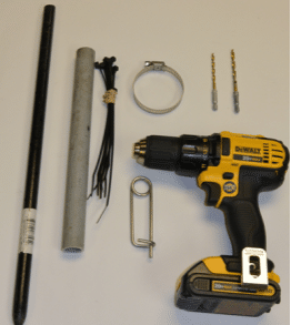
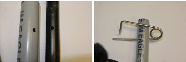
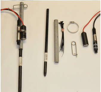
Figure 6.5.4 A. Steel rebar pin (round steel stake with pre-drilled holes). Black steel stake with a pointed end, available in either 2’ or 3’ lengths at Lowe’s Home Improvement.
Figure 6.5.4 B. Grey PVC conduit with drilled hole. Plastic electrical conduit, ¾” grade available in 5’ lengths at Lowe’s Home Improvement. The PVC is cut in the field, to a specific length, to fit over the black rebar in the stream bed. A hole must be drilled either 1 ½” (if using 2’ black rebar) or 3¼” (if using a 3’ black rebar) from the top of the PVC to match exactly to the first hole in the black rebar.
Figure 6.5.4 C. Outdoor black zip-tie to secure the sensor wires. Note: using regular white zip ties in outdoor conditions will not be sufficient as they tend to break easily when subjected to cold/heat/sun.
Figure 6.5.4 D. Retaining pins. Stainless steel bent wire locking pin available through McMaster-Carr. This is the mechanism that secures the PVC pipe to the black steel rebar at a fixed depth.
Figure 5.5.4 E. Hydros 21 CTD sensor by METER Group Inc. Electrical Conductivity Temperature Depth sensor.
Figure 6.5.4 F. Campbell OBS-3+ sensor by Campbell Scientific. Optical backscatter Turbidity sensor uses its sideways-facing optics to emit a near-infrared light into the water. It then measures the light that bounces back from the water’s suspended particles.
Figure 6.5.4 G. Large hose clamp. Hose clamp with 410 Stainless Steel Screw, ½” Wide Band. available from McMaster-Carr.