
Home › Forums › Mayfly Data Logger › Mayfly v1.1 technical questions forum thread
Tagged: #Mayfly #ROSSERIAL
- This topic has 63 replies, 13 voices, and was last updated 2026-01-07 at 7:40 PM by
 Shannon Hicks.
-
AuthorPosts
-
-
2022-02-23 at 10:49 AM #16619
This is the forum thread to ask general technical question about the Mayfly v1.1 board. If you’ve got a basic question such as what are the board’s features or how it differs from previous versions, this is the place to ask. If you’ve got a more complicated question or issue, then it is probably best to start your own thread. The goal of this thread is to be a great information resource for basic questions about the new v1.1 board that are common to all users.
For questions about purchasing and availability of EnviroDIY products, ask those on the dedicated Status and Availability forum thread if the aswer isn’t readily apparent from the table on the main EnviroDIY Hardware Status and Availability page.
-
2022-02-23 at 10:49 AM #16615
Hi Shannon,
Is there a topic describing changes from Mayfly V1.0 to V1.1? If not, can you describe?
Thanks,
Mike
-
2022-02-23 at 10:57 AM #16616
The only difference between versions is stated in the first paragraph of the blog post: the only major change being the circuit that provides the switchable 12 volt boost output was redesigned to provide a higher power output. And 2 minor changes: one set of pin labels were slightly change and one solder jumper was added to the back of the board for an optional battery-measuring feature. (see more at Details and Specs)
-
2022-02-23 at 11:35 AM #16617
Thanks!
-
2022-03-16 at 11:19 PM #16745
Hi @shicks I got my 5 pack of the v1.1 boards today and I noticed that:
- Removed External/Lipo slide switch since it’s no longer needed
Does that mean I can no longer power the Mayfly from a 12 V supply? I have an application for water sampling and the pumps run on 12V and they are controlled by the Mayfly so I can power the whole system with a 12V utility lead acid m/c battery.
-
2022-03-16 at 11:40 PM #16746
That is correct, the Mayfly v1.0 and 1.1 boards do not have a separate external power input for 4v to 12v sources like the v0.5b boards. This is because the main voltage regulator on the v0.5b board that accepted that wide range of voltage was discontinued by the manufacturer, and the new voltage regulator doesn’t accept that high of an input voltage. However the tradeoff is that the new regulators have double the current output (1 Amp instead of 500 mA).
To power a Mayfly v1.0 or v1.1 board from a 12v battery, I’d suggest a 12v-to-5v power adapter with a USB-C plug on the end, and just plug it into the Mayfly’s USB port, and preferably one with a low quiescent power draw so that it doesn’t waste too much power on the dropdown. I think a few people on the forum here have recently mentioned adapters that they’ve had either good or bad results with. Something like this might work, but I haven’t test this exact model so performance results with a Mayfly aren’t guaranteed. You should also turn off the dip switch (after programming and when you’re ready for deployment) for the USB LED because it’ll save several mA of current for the LED and about 10mA of current for the CP2102 USB adapter chip that is powered anytime the Mayfly v1.0 or v1.1 is powered by a USB cable.
The other improvement of the new Mayfly boards when paired with the new sim7080 LTE cell boards is that these cell boards no longer require a direct connection to a 3.7v lipo battery like the Digi LTE boards did with the custom adapter board. Those older setups were harder to power from a 12v battery because you still needed to provide a separate Lipo battery for powering the LTE board. Now with the new sim7080 LTE cell boards, everything can be powered from just the 5v USB connector with no external lipo necessary.
-
2022-03-21 at 3:34 PM #16805
Shannon,
I ordered several boards in the 1.0 release in the fall as replacements for 0.5 boards that are currently in the field. Our setup for those involved using DIN rails to connect large marine cycle batteries so we could keep our terrestrial stations operational during the winter. So, we used the 12v regulator on the 0.5 board and it has worked really well.
For the 1.0 boards, I wonder if we could order a bare wire version of the step down module you linked, and then just connect that to a JST connector for where the solar panel input is. Can you think of any issues that may arise with that type of setup?
Sincerely,
Dave
-
2022-03-21 at 6:46 PM #16806
Powering the Mayfly v1.0 and v1.1 from the solar jack only would not be recommended because the power input circuit was not designed to operate that way. The most electrically efficient way is to use the 12v-to-5v converter and connect it to the USB-C jack and then deactivate the USB interface circuitry with the dip switch as explained above. The Mayfly will not operate properly if you only provide power to the solar jack with no 3.7v Lipo connected to the LIPOBATT jack.
-
2022-03-22 at 2:57 PM #16810
Thank you so much Shannon!
One very minor last question – for the DIP switch, that would be turning the USB DIP to ‘off’ for the purposes of LED operation, correct? The ‘Power’ DIP switch would remain ‘on’?
Thank you!
Dave
-
2022-03-22 at 3:10 PM #16811
The dipswitches are mainly there to let people know their board is working during initial testing or desktop deployments. Anytime a board is deployed in the field as a “sleeping” station, power savings are important during the sleep period. So I put the dipswitches on the new versions of the Mayfly to allow people to deactivated the LEDs. The dipswitch for the green LED only cuts power to the green LED and nothing else, but it will save you about 2 mA. The orange LED is only on if power is being supplied through the USB jack, like when connected to a computer or when powering from the USB jack like what that converter will do. Whenever the USB jack is powered and the USB dipswitch is on, the LED is on plus the USB converter chip, which draws some not-insignificant power, so turning off the USB dipswitch will save power and prevent the USB converter from being on constantly. However, you’ll just have to remember to turn that dipswitch on again in the future if you ever decide to reprogram that Mayfly or want to connect to the Serial Monitor to see some output.
There’s a description of the dipswitches and all the new circuitry on the Mayfly Hardware Details page.
-
-
-
2022-03-17 at 11:42 AM #16752
Thanks! I just ordered two. My four port sampler project uses 12V motors which draw about 0.4A so I guess that would be an option to use the 12V output and LiPo 3.7V batteries.
I assume this converter uses switching so it should be reasonably efficient. I’ll le you know how they work. Good old amazon – I should get them tomorrow!
-
2022-03-17 at 11:59 AM #16753
As stated on the Details and Spec page, the Mayfly v1.1 can only source about 100mA from the 12v output, so if your motor draws 400mA, you’ll need to power the motor directly from your 12v source and not from the Mayfly.
-
2022-03-21 at 9:14 PM #16807
@shicks. I tested the converters you recommended and they appear to work as expected:
dropout voltage is 8 Volts and will support input voltage to 31.5 V (max on my bench PS).
No load draw is 3.64 mA at 12 V and 2.83 mA at 31.5 V.
A lower cost option is a three terminal non-isolated converter at $2.76 ea vs $12 for the PlusRoc.
-
2022-04-29 at 2:32 PM #16977
My USB connect to a rev1.1 board appears to be failing.
It was working, and now its stop connecting to the PC, stops even causing an audible ding.
If I take the same USB C cable and plug it in to the USB C of a Rev1.0A3 it sometimes works. Usually causes an audible ding, but sometimes doesn’t appear as a com port.
I’ve rebooted my PC twice, and left the Rev1.1 board powered off overnight to see if it might recover.
Just wondering any suggestions for what might be the issue, or way of checking the driver.
I am seeing the boards work through the FTDI connector.
-
2022-05-02 at 10:55 AM #16984
Are you saying you’ve got a bad cable or a bad Mayfly? Have you tried a different USB-C cable? The pins in USB-C connectors and cables are extremely small and are easy to fail. And when the pins in a cable’s connector get bent or damaged, we’ve seen them inflict damage on brand-new boards, so I’d suggest trying a new cable or two.
-
-
2022-05-02 at 12:14 PM #16985
Suspect Mayfly1.1
The cable I was using also went bad and I’ve marked it as suspect – its a distinctive pink cable. I’ve inspected the Mayfly USB c on Mayfly1.1 with an Eye Loupe, and it is hard to inspect but nothing jumps out, seems OK.
I did have a USB current monitor in the testing before hand, and the current had gone up to 1.2A while charging a 2.2Ahr battery – but difficult to know if it was related. However the Mayfly options are not set to do a high charge, just 0.5A.
I switched to Linux Ubuntu to get more details, and a sturdy USB-C interface and I get with working White Cable into Mayfly1.0
dmesg
[20236.503620] usb 5-1: New USB device strings: Mfr=1, Product=2, SerialNumber=3
[20236.503624] usb 5-1: Product: EnviroDIY Mayfly USB to UART Controller
[20236.503627] usb 5-1: Manufacturer: Silicon Labs
[20236.503630] usb 5-1: SerialNumber: 0001
[20236.565048] usbcore: registered new interface driver usbserial_generic
[20236.565911] usbserial: USB Serial support registered for generic
[20236.586585] usbcore: registered new interface driver cp210x
[20236.586749] usbserial: USB Serial support registered for cp210x
[20236.586863] cp210x 5-1:1.0: cp210x converter detected
[20236.594710] usb 5-1: cp210x converter now attached to ttyUSB0
but then insert into Mayfly1.1 it doesn’t respond on the USB. It does get powered,
I think I have all the switches right, but here is a video https://photos.app.goo.gl/2n43i7qjLGmwbiQz7
-
2022-08-25 at 8:17 PM #17282
I need to calculate the expected power consumption for a 10 month deployment, fully battery powered (no solar). Where can I find specs on the Mayfly power consumption? I realize that it will vary depending on dip switch settings (as Shannon mentioned above), so data to calculate power consumption based on their settings would be amazing.
Thanks – Dawn
-
2022-08-25 at 9:33 PM #17283
We’ve release several different Mayfly Data Logger hardware versions in the past few years, so I’d need to know which version you’re using. I’m assuming a v1.0 or 1.1 since you mentioned deactivating the LEDs using the dip switches. But it also depends on the sampling interval you’re planning to use (time between measurements when the Mayfly is sleeping), active sample duration (time it takes to make a sensor reading) and the total time the Mayfly will be awake during the sampling and recording/transmitting period, what sensors you’ll be using, will you have a microSD card on board that you’ll write to every sample, will there be a telemetry module (wifi, cellular, radio, etc), and what’s the temperature range the station will be subjected to during the deployment.
-
-
2022-08-25 at 11:41 PM #17284
Yes, on all those dependencies. I’ve ordered but haven’t received the Mayfly 1.1. I need to choose the sampling interval and battery mAh for the system so that we can get the most data over the deployment period with plenty of spare power capacity to ensure data collection at the end of deployment, which is the most important.
I have all the mA pull for the Atlas sensors and their electrical isolation boards. I’ll be using a Whitebox T1 (https://atlas-scientific.com/electrical-isolation/whitebox-t1/) for some of them and have asked for that power draw. It has an integrated SD card port. There won’t be any telemetry as we’re deploying them in an Antarctic lake and retrieving them after ~9 months. The temperature will be 1.0° C (the temperature of the lake water) plus the heat produced by the electronics in the underwater housing.
In looking at batteries, I think I’m going to power the Mayfly, Whitebox, and 4 additional sensors separately. Thus, I need to know what the Mayfly will draw under my conditions to choose an appropriate power source.
-
2022-08-30 at 11:52 AM #17289
Mayfly v1.x power usage (with no external sensors attached) and both LED dipswitches off (the brown/white slide switches between the main power switch and the vertical SD card socket) is as follows:
Mayfly current when board is powered and idle: 6.5 mA
Mayfly current when MCU put to sleep and no microSD card in socket: 0.27 mA (or 270 uA)
Mayfly current when asleep with microSD card in the socket: 0.43 mA (or 430 uA)
-
-
2022-08-30 at 6:11 PM #17292
Thank you so much, Shannon!
-
2022-08-31 at 12:03 PM #17293
This may have been asked already.
The Mayfly v1.1 board. What is the temperature range that this board can stand for a closed up box? Also, we have the 4400mAh LIPO battery, Operating and charging with the solar panel. What is the min and max temperatures can this battery stand with a closed up box?
Thanks,
Rogers
-
2022-09-01 at 12:01 AM #17295
The components on the Mayfly circuit board are rated to withstand the industrial temperature range of -40C to +85C. Here in Pennsylvania, our loggers don’t normally see that full range during normal deployments, but this summer we frequently reached almost 60C with one of our loggers that is mounted in an open field inside a clear plastic Pelican case. Our other nearby stations in the standard opaque tan Pelican cases reach around 40C most summer days. In previous winters they measured down to -25C with no problems. Likewise, the lipo battery packs have done well in all the stations except ones that have condensation in them, because we’ve found that the blue 4400mAh battery packs are susceptible to damage from being exposed to moist environments because the metal tabs under the plastic end caps will rust very easily and cause the battery to open-circuit. In stations that stay dry inside, usually with the help of desiccant packs, can use the same battery for multiple years with no problems. We’ve got several stations that are still using the same Mayfly and lipo pack from 5 years ago and have been in continuous operation with no issues.
-
-
2022-09-02 at 7:57 PM #17298
For the battery, seems to me there are two engineering approaches, specification and characterization.
For the specified battery 4400mAh https://www.adafruit.com/product/354
which has a listed data sheet from the manufacturer – https://cdn-shop.adafruit.com/product-files/354/C449_-_ICR18650_4400mAh_3.7V_with_PCM_20140728_APPROVED_8.18.pdf
it has a defined “Operating Temperature” of Charge: 0-45C, and Discharge -20 – 60C.
If you go outside those parameters, for too long (!) – some may still operate – but now its characterization as to how many will operate.
Of course manufacturers do characterization upfront on their products, to be able to come up with a specification they stand by across all that product range. -
2022-09-14 at 10:57 AM #17321
When I first received the Mayfly V 1.1 a few weeks ago, I hooked up the all of the connections: Battery, Solar Panel, and sensor. Everything worked fine. Over the last week I have noticed that the yellow solar charging LED is not lit when the Sun is out. However looking at the CSV generated file the voltage is higher like the panel is charging the battery and the voltage is lower when the Sun is down.
I have checked the Solar Panel to external cable connection, the connection to the Mayfly board. Everything looks OK.
Is the LED light just burned out? Does the board have a malfunction? Or do I just keep an eye on the voltage levels like I am doing?
Thanks for your help, Roger
-
2022-09-15 at 10:32 AM #17331
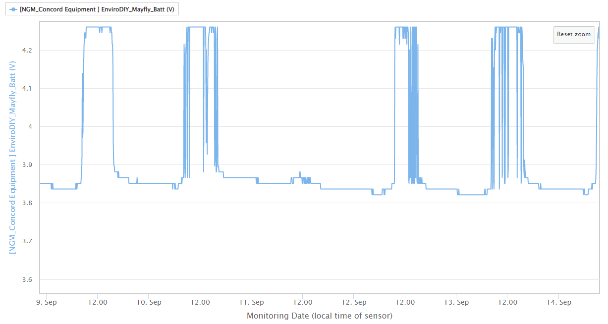
As Neil mentioned above, the yellow LED that is labeled SOLAR only indicates when a charge current is being applied to a battery, so if a battery if fully charged (~4.2v), the LED will not be on. The charging circuity of the Mayfly v1.1 boards is configured so that the solar panel provides voltage directly to the Mayfly’s main power regulators when the sun is out (and also charges the battery) and it uses the Lipo battery as kind of a “backup” source in case the Mayfly draws more current than the panel can provide. When there’s insufficient power collected by the solar panel (like at night or in really shady locations) then the main power for the Mayfly comes from the battery. If you’re using analog pin A6 to monitor the input voltage, you’ll see the raw battery voltage at night (anywhere from 3.5v to 4.2v), and during the day you’ll usually see something between 4.1v and 4.25v (depending on the amount of sunlight). In the attached graph image below, you can see the raw battery voltage is around 3.85v.
You can actually get useful information from this plot like that because it shows you what days were sunny and what days were cloudy, which could help you understand why the underlying raw battery voltage might increase or decrease over time. For example, in the plot below you can see it was completely sunny on September 9, mostly sunny on Sept 10, totally cloudy on Sept 11 (no charging at all), and mostly sunny on the 12th and 13th. Every station is going to have a different charging pattern based on tree canopy, time of year, weather, obstacles, etc, but having the graph showing the input voltage to the Mayfly can be very useful for monitoring the overall status of a station. Also, if a Mayfly is being powered directly through its USB port (with or without a Lipo also connected to the Lipo socket), then the voltage measured by the analog A6 input will show 4.95v.
If you would rather monitor the raw Lipo battery voltage and not see the swings of the solar panel (or USB) input, then you can follow the directions mentioned below, which come from the Mayfly Jumper Settings page.
SJ27: Analog pin A6 connected to either combination Voltage in (default) or direct Lipo battery socket. The default setting works best so that the Mayfly can sense the input voltage of whichever source is highest. With just a Lipo connected, A6 will see the battery voltage (~3.7v). If a solar panel is connected, then A6 will see approximately 4.2v during full sun. If a USB cable is connected, A6 will see 4.9v. If you want to see only the raw Lipo battery voltage independent of the higher voltage from the solar panel, change the solder jumper to Lipo.
Attachments:
-
2022-09-15 at 12:07 PM #17333
Thanks for the great answers. These are really helpful. There are so many things to dig into with this system. It is easy to miss some of your notes and instructions. I am finding that it requires a lot of deep diving into information. I am trying to build a process for our folks to follow that will be simple to understand. There are a lot of people with no hardware or Unix experience. We are also going to have to get all the data manually and upload manually. There is no cell service in 99% of our device locations.
-
-
2022-09-14 at 3:42 PM #17325
@rogers1313 my systems only have the Yellow led ON when actually charging. If the battery is charged, not charginng then it is OFF. The description in “Section S”, beneath the pics https://www.envirodiy.org/mayfly/hardware/details-and-specs/ says
A yellow LED (labeled CHARGE) will light anytime the battery is being charged. Once a battery is fully charged, the yellow LED will go out, indicating that charging is done.
-
2022-09-15 at 12:08 PM #17334
Thanks for this answer, too. It is most appreciated.
-
-
2022-10-06 at 7:42 PM #17385
I have a new Mayflyv1.1 board and it does not recognize the microSD card (it’s side loaded into the board without any adapter). I am using the mayfly1_TempHumidLight_simpleLogger example with no changes. When I turn on the Mayfly board, I get:
123Mayfly SHT40-Light LoggerError: SD card failed to initialise or is missing.Data Record: 2000-01-01 00:00:09,9,4.88,49.90,27.26,10.9112I’ve tried a couple of different microSD cards, both of which work for other devices. How should I approach debugging this or might it be a hardware problem?
-
2022-10-06 at 7:52 PM #17386
As long as the cards are formatted for FAT32 and you can read/write to them with other Mayfly boards or Windows devices, then it’s possible the on-board memory card socket on that Mayfly is broken. Is this a brand new board that you’re using a card in for the first time? If you’ve got an EnviroDIY vertical microSD adapter you could try putting that on the Mayfly to see if a card will work in there, but sometimes we’ve found that the defect in the on-board socket causes the vertical adapter to also not work properly (because they both essentially share the same pins). You can email me at mayfly@envirodiy.org and we can arrange the warranty support.
-
-
2022-10-06 at 8:05 PM #17387
It was ExFAT formatted, now FAT32 formatted and working! It’s great when the fix is so easy. Thank you!
-
2023-02-10 at 12:25 PM #17598
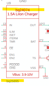
I don’t have a ton of experience reading schematics, so I could be in error here. But FYI, it appears there may be an inconsistency in the v1.1 rev A schematic regarding the part number of the LiIon Charger chip. Please see attached screenshot. (Also understanding that these things are a moving target as chip availability changes.)
-Matt
Attachments:
-
2023-02-10 at 7:21 PM #17600
The correct part number for U9 is bq24074, as shown in the red text at the top of the schematic symbol. Apparently the device properties in the Eagle library that I got from Adafruit two years ago for that component have an incorrect value printed below the symbol diagram on the schematic file only, but the BOM produced from that schematic file, as well as the manually-created BOM I give the manufacturer for producing all of the Mayfly boards specifies that the part number is bq24074, and the footprint for the part on the board layout is the correct footprint for that component (16-pin QFN). I didn’t put that incorrect number at the bottom of the schematic symbol, but it doesn’t affect anything about the functionality or manufacturing of the board, so it can be ignored until I can remove it from the file.
-
2023-03-03 at 1:55 PM #17657
How do I switch over to the 12 volt power supply? The Board Features Overview page says the 5 and 12 volt circuits can be accessed from pin D22, but I am having trouble finding that pin. I notice there are some pins labeled Sw3, Sw5, and Sw12 at the bottom of the 20-pin headers. Is that where I switch the supply voltage, and if so, which pins am I connecting? I am also a little confused on how the jumper pins that sit at the head of the grove terminals work. Do I need to move the jumper pin for the grove terminal I plug into if I switch the power supply? Thanks!
-
2023-03-04 at 12:55 PM #17668
There are multiple sources of power on the Mayfly boards. There’s 3.3v that’s always on, then there’s a separate 3.3v regulator that can be switched on and off by setting pin D22 high or low in your code. There’s also a separate 5v boost regulator (and on Mayfly v1.x) a 12v boost regulator, both of which are also controlled by D22 in your sketch. There’s actually no physical access to pin D22 to the users, it’s simply the trace from the ATmega1284P chip to the regulators that gets set high or low by your sketch. All 3 of the switched regulators are active-high, meaning setting D22 high will activate the regulators, and setting D22 low will deactivate the regulators.
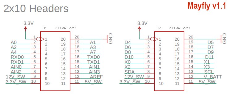
You can access the switched 3.3v, 5v, and 12v power output lines in two different methods. One is through the 2×10 headers on either side of the Mayfly. Both headers have the same power and ground outputs: GND, 3.3v (constant). and the three switched power of Sw3, Sw5, and Sw12. These headers are used if you’re using a shield or mini-shield or accessory board that needs access to either the analog (left hand side) or digital (right hand side) pins.
Most people connect external devices to the Mayfly via the handy polarized 4-pin Grove jacks. The Grove jacks contain 2 data lines, one ground line, and 1 power line. The voltage of the Grove jack power line is determined by the position of the tiny jumper headers next to the individual Grove jack. Follow the label next to the jumpers to select the proper voltage you want for that Grove jack. The default setting as shipped out initialy is 3.3v, so move a jumper to the 5v or 12v setting to make the V pin of that adjacent Grove jack either 5v or 12v.
There have been multiple revisions to the Mayfly board over the past 7 years, resulting in different voltage output options and different jumper pin arrangements and orientations and labels. Details of these settings and photos showing non-default examples can be found on the Mayfly Jumper Settings page.
-
2023-04-12 at 8:12 AM #17722
On a Mayfly V1.0 Rev A3, is power to the 2X10 analog header controlled by pin 22 or is the header constantly powered? I’m trying to utilize power from the 2X10 analog header while the grove ports are not powered (pin 22 is low) if this is possible.
-
2023-04-12 at 9:16 AM #17723
There’s one 3.3v regulator that’s always powered on the Mayfly (anytime the Mayfly power switch is ON, even if the processor is put to sleep), and that can be found along the top (inward end) of each of the 20-pin headers, helpfully next to the GND pin you’d also need for sending power to an external device. The three switched power options (3.3v_SW, 5v_SW, and 12v_SW) are available on the other end of the headers, and are controlled by pin D22. I’ve attached a cropped snippet from the Mayfly schematic showing the header pinouts, since it’s sometimes hard to read the labels on the actual boards. This attached pinout image applies only to the v1.0 and v1.1 boards. Previous versions had different pinouts because of the different design changes between versions. All the full schematics are available in the Board Schematic section of the Mayfly hardware page.
Attachments:
-
-
-
2023-03-15 at 11:15 PM #17691
@shannon I am setting up a new sensor station using the hydros 21 (due in tommorow) but I am not using the turbidity sensor. I deleted that section of the code but I wanted to add the humidity sensor. What do I need to put in the variable list? Here is what I have:
Variable* variableList[] = {
new MeterHydros21_Cond(&hydros),
new MeterHydros21_Depth(&hydros),
new MeterHydros21_Temp(&hydros),
new MaximDS3231_Temp(&ds3231),
new ProcessorStats_Battery(&mcuBoard),
new ProcessorStats_Battery(&mcuBoard), //dummy var as place holder for humidity
// new SensirionSHT4x_Humidity(), //use “humidity” variable; get error
new Modem_SignalPercent(&modem),
};The modem is communicating with the new sensor site ok
What else am I missing?
Thanks
-
2023-03-16 at 1:40 PM #17692
@w3asa Did you look at this example: https://github.com/EnviroDIY/ModularSensors/tree/master/examples/DRWI_Mayfly1. I think it’s almost exactly what you want.
-
2023-03-16 at 4:02 PM #17694
Thanks! I’ll plug that into my code.
-jim
-
2023-03-16 at 9:38 PM #17695
-
2023-03-17 at 7:45 AM #17696
The sensor manufacturer has assured me that the sensors will work at 3.3v, and we’ve had experience with hundreds of them and concur, but they’ll also work just fine with the jumper set to 5v instead, so it’s your choice.
This thread is for overall technical questions about the hardware on the Mayfly v1.1 boards, so if you have other questions about code or specific sensors, it would be best to start a new thread for those topics.
-
-
-
2023-05-26 at 2:54 PM #17845
How do the analog pins found on the 20-pin header (pins A0, A1, A2, etc.) differ in function and purpose from the auxiliary analog pins (AA0, AA1, etc.)? From what I’ve seen, you need to connect analog sensors to the auxiliary analog pins and use an Adafruit library to get the millivolt readings because of an ADC they are connected to. I’ve successfully done this, and it has worked great, but I guess I’m curious what the other analog pins (A0, A1, etc.) on the 20-pin header are used for and what type of sensor outputs would be used on them.
-
2023-05-26 at 11:15 PM #17847
The ATmega1284P processor of the Mayfly is similar to other basic Arduino boards with the 324P processor in that it has an internal 10-bit Analog-to-Digital converter (ADC). There are 8 ADC pins on the 1284P (not all 8 are available on the Mayfly header because some are permanently designated for certain measurements or functions), so these ADC pins can be used to read analog voltages, however at a pretty coarse resolution (1024 bits over the 3.3v sample range). But these analog pins can also be used as digital pins just like the regular digital pins (D6, D7, etc). So you can use statements like digitalWrite(A2) or digitalread(A2) if you’ve run out of regular digital pins and need some extra inputs or outputs.
The AuxAnalog pins on the Mayfly are unique in the Arduino board ecosystem because it’s a separate ADS1115 16-bit ADC that included on the Mayfly board. That chip allows multiple high resolution readings (either 4 single-ended or 2 differential) and faster sample rates, so if you’re trying to precisely read an analog voltage with a Mayfly, then using the AuxAnalog pins will usually give you better and more accurate readings (when done properly).
-
2023-05-30 at 11:37 AM #17850
Okay, thank you Shannon! I have a follow-up question. So when using the AuxAnalog pins, from my understanding you have to multiply the digital signal by 0.1875 to convert it to a millivolt reading. Would you need to do the same if you were to use the other analog pins (A0, A1, ,etc.), or is the 0.1875 value unique to the ADS1115 ADC?
-
2023-05-30 at 4:16 PM #17851
The calculation for the conversion of analog bits to voltage depends on the operational voltage of the system (3.3v in our case) and the resolution of the ADC. You can see an example calculation (and more importantly, the formula used) for a 10-bit Arduino here: https://learn.sparkfun.com/tutorials/analog-to-digital-conversion/all
-
2023-05-31 at 1:54 PM #17855
I am confused on how we get the 0.1875 conversion factor for the 16-bit ADC. Does it operate on a different voltage? In my mind, if the board operates at 3.3 volts and there are 65,535 bits, then you would be multiplying the analog reading by 3300 mV / 65,535 bits, which is 0.050 mV / bit.
I’m asking because I am looking at connecting two apogee thermopile pyranometers and two thermopile pyrgeometers to the Mayfly (which will require more than four analog pins), and I am curious if the 10-bit ADC would have sufficient resolution for some of the sensors. Once I know how many millivolts are represented in each bit, do I just compare the ADC resolution with the sensors’ sensitivity, or what is the best way to make sure that I am using an ADC that has a good enough resolution for my sensor?
-
2023-05-31 at 3:41 PM #17857
The ADC example I linked above from Sparkfun applies only to the onboard 10-bit ADC of the ATmega1284 processor. For the ADS1115 auxiliary ADC on the Mayfly board, the formula on the Sparkfun page does not apply, because the ADS1115 is a dedicated ADC chip and works differently. The operational specs of the chip are outlined in the TI datasheet (found here), and specifically page 17 talks about the resolution of the readings at different gain settings. The default gain of the ADS1115 is two-thirds (also listed as 6.144v FSR), so therefore the LSB (least significant bit) as shown in Table 3 is 187.5 uV, or 0.1875 mV.
You can also see a breakdown of the sensitivity of the chip at different gain settings in the beginning of most example sketches for the ADS1x15. Like here: https://github.com/adafruit/Adafruit_ADS1X15/blob/master/examples/singleended/singleended.ino
Note that there are 2 popular varieties of the ADS1x15 chip that Adafruit sells, so their example sketches usually are written for one or the other, but usually mention both and it’s up to the user to edit the code to use the correct version. ADS1015 is the 12-bit (not on the Mayfly), and ADS1115 is the 16-bit (what’s on the Mayfly). So in that Adafruit example on Github above, to work on a Mayfly you’d need to change the example code to comment out line 4, and un-comment line 3, so that the code uses the correct settings for the ADS1115. The comments in line 20-25 show the table for the different gain settings that’s the same table as shown in the TI datasheet. The default gain setting for the ADS1115 is the two-thirds gain, so we usually just use that as-is. If for some reason a user needed better resolution than 0.1875mV, they could adjust their code to use a different gain setting, but we’ve found for most purposes, the default gain is sufficient and using a different gain setting just introduces more noise into the measurement unless certain precautions are taken. Usually just taking multiple readings in close succession at the default gain setting and then averaging them will be adequate.
-
2023-06-06 at 1:05 PM #17868
Is the 3.3 V for the 10-bit ADC on the Mayfly a value that is fixed, or can it be changed? I don’t know if this is related or not, but does the ADC voltage come from the default analog reference, or is it completely different? Could the analog reference voltage be lowered, using the analogReference() function, giving us a higher resolution as a smaller voltage is spread over the same amount of bits? Again, I don’t know if that is what the ADC voltage is tied to, but it is something that was brought to my attention, and I wanted to see if that’s a possibility or not.
-
2023-06-06 at 5:42 PM #17870
The analog reference voltage (AREF) pin of the ATmega1284P is broken out to the left-hand 2×10 header if you wanted to apply a voltage other than (and less than) 3.3v. If you leave it floating and don’t specify the AREF in your code, then it’ll use the default 10-bit setting for any regular analog reading like you’ll find in most code examples. If you apply a voltage other than 3.3v to AREF, you’ll need to add code to tell the sketch that you want to use AREF as the reference, plus take that into account for any ADC calculations you make. So follow examples you might find online for other Arduino boards for using a custom analog reference. I broke out the AREF to the header in the rare chance that someone would want to use it, but we found that most people are much happier with the increased resolution and sample rate and code flexibility of the aux ADC that I don’t know of anyone actually modifying AREF, but the capability is there on the Mayfly board if you want it.
-
2023-06-06 at 5:57 PM #17871
Okay, gotcha. It’s of interest for me because I am looking at attaching multiple apogee pyranometers and pyrgeometers to the Mayfly that are all analog outputs. Because the pyrgeometers also require adjustments based on an internal thermistor reading, it would require more than 4 analog pins, so I am just seeing if I could get a decent resolution from the 10-bit ADC on some of the sensors while the rest operate on the 16-bit ADC.
-
-
-
2023-06-06 at 8:42 PM #17873
There is some onchip references, but maybe not useful. From the manual mega164A_PA-324A_PA-644A_PA-1284_P_Data-Sheet-40002070B.pdf (applies to the mega1284)
Chp 23.2: “<span class=”fontstyle0″>Internal reference voltages of nominally 1.1V, 2.56V, or AV</span><span class=”fontstyle0″>CC </span><span class=”fontstyle0″>are provided On-chip. The voltage reference may be externally decoupled at the AREF pin by a capacitor for better noise performance. </span> ”
However the benefit of the 3.3V is that its +-1% – whereas the 1.1V and 2.56 are +/- ~10%
-
2023-06-06 at 9:06 PM #17874
Reminder quote from the first post of this thread: If you’ve got a basic question such as what are the board’s features or how it differs from previous versions, this is the place to ask. If you’ve got a more complicated question or issue, then it is probably best to start your own thread. The goal of this thread is to be a great information resource for basic questions about the new v1.1 board that are common to all users.
I’d recommend taking these detailed technical questions to their own specific thread in order to keep this one short and easy for all users to read about the technical differences between the latest Mayfly version and previous ones.
-
2023-08-31 at 3:21 PM #18049
Hi @shicks, just received two Mayfly 1.1 and noticed they are rev1.1B – just wondering what the differences are from rev1.1A? 🙂
I did pull the circuit diagram from https://www.envirodiy.org/mayfly/hardware/ however the resolution is so low, its not all readable. Just wondering if there is a pdf version. 🙂
I also checked https://github.com/EnviroDIY/EnviroDIY_Mayfly_Logger/tree/master/hardware but couldn’t see anything.
Many thanks
-
2023-08-31 at 6:42 PM #18055
The only differences between the v1.1 revA and revB are this:
The ICSP jack was a 2×3, 0.5″ pitch male pin header on Mayfly v1.1 revA.
The ICSP jack is now uses Tag-Connect pads for use with Pogo pins for ICSP programming for the Mayfly v1.1 revB.And with the revA boards, there was a circuit design change after manufacturing that required me to hand-solder a small jumper wire to bypass solder jumper SJ26. It is noted on the schematic. That change was incorporated into the production run of the revB boards, so electrically, revA and revB boards are the same, except there’s a physical wire on revA and a board trace on revB. There’s also a dab of conformal coating covering SJ26 on all revA boards to prevent it from being used. This is noted on the Jumper Settings page if you scroll about halfway down.
As for the schematics, they are available for all version numbers via the links on the Hardware page you linked. Click on the name of the desired schematic version, it’ll take you to a preview page. The schematic shown on that page can appear fuzzy or low-res depending on your web browser and monitor size/resolution. But simply click on that image of the schematic and you’ll be taken to the actual pdf file which is a high-res 11×17 pdf that can be printed or zoomed in on, allowing you to see all the details.
-
-
2023-09-01 at 2:25 PM #18056
Many thanks got it. I appreciate the effort and detail that goes into producing a new production run. The pogo pin connector is great and so simple.
Got the .pdf – I copied the .jpg instead of more intelligently clicking it to get the .pdf!
Just wondering if you have any thoughts on changing the Vbat Rs to 1M / 270K for better noise immunity. It wouldn’t change the functionality, only provide a cleaner Vbat measurement . I can provide you some technical references on pop corn noise in higher value R if its of interest. https://github.com/EnviroDIY/EnviroDIY_Mayfly_Logger/issues/36
-
2023-10-17 at 12:06 PM #18109
Hello! I was wondering if the Mayfly has the ability to communicate with other Arduinos, preferably the Nano?
Thank you in advance!
-
2023-10-17 at 12:17 PM #18110
It depends on what you mean by communicate. Are you wanting to transmit data wirelessly between a Mayfly and another Arduino-compatible device? Or are you meaning a direct cable connection between the two devices? Either way is possible, but it really depends on a lot of factors, like what sort of data are you transferring, how often, and why.
As stated in the first post on this thread: This is the forum thread to ask general technical question about the Mayfly v1.1 board. If you’ve got a basic question such as what are the board’s features or how it differs from previous versions, this is the place to ask. If you’ve got a more complicated question or issue, then it is probably best to start your own thread. The goal of this thread is to be a great information resource for basic questions about the new v1.1 board that are common to all users.
So I’d suggest creating a new topic in the Mayfly forum for your question.
-
-
2023-12-06 at 2:26 PM #18214
Hi,
What is the maximum recommended amps from a 6 volt solar panel to the V 1.1 board? Is this different for previous boards? There are two solar inputs–are these the same input but different connectors?
Thanks
EDIT: I see the data sheet for the BQ2407x charger but don’t understand it. Is the input current from the solar panel limited by the BQ24074? Also I see on the board diagram that the two solar inputs are the same.
-
2023-12-06 at 2:51 PM #18215
The very bottom-left corner of the schematic for board v1.1 mentions the two charge rates, which you can control using solder jumper SJ15. Here’s the description of that jumper from the Jumper Settings page:
SJ15: Lipo battery charge rate: 500mA (default) or 1A. This jumper allows you to select the maximum charger output current of the onboard Lipo charger. Default setting is 500mA (solder jumper open). Add a solder bridge to increase the rate to 1A. Note that you’ll also need to close jumper SJ14 (set input limit to 1A) in order to get 1A charger output. This setting should only be changed if your input power source can supply more than 500mA. Setting the rate to 1A also causes the bq24074 charger chip to get extremely hot during charging, so use caution.
There are 2 solar panel jacks on the Mayfly v1.0 and v1.1. This was done to provide backwards-compatibility for older existing stations that still have the white JST plug soldered to the end of the solar panel extension cable. Since most people don’t want to have to solder things when assembling their kits, we switched to using the black quick-connect jack in 2021 so that people could simply insert the bare leads of the solar panel extension cable into the plug without having to solder anything. Only one solar panel jack should be used on a deployed station though. The 2 options are there just for convenience. Likewise, there are still 2 JST jacks labeled LIPO BATT, but users should only connect one battery at a time. The second jack is a legacy feature from many years ago when we used cellular boards that required a direct connection to the battery using a little double-ended JST cable. It will likely be removed from future Mayfly versions to eliminate confusion.
-
2023-12-06 at 3:46 PM #18216
Shannon, thank you. I will keep it at 500 mA, while increasing the solar panel wattage to provide more hours of charging at 500 mA.
-
-
-
2026-01-07 at 4:59 PM #19478
The Mayfly board we have is distinctly different from the board in the video. We have version 1.1 revision B board # 25069. When we try to put in the UUI for data sets for the conductivity probe we get a compiling error message at the very last step. I did not post this on the forum yet because I suspect we have a newer version of the board. Any help would be appreciated.
Thanks Mark
-
2026-01-07 at 7:40 PM #19479
This thread is for general technical questions about the Mayfly v1.1 board. I don’t know what video you’re referring to, but I assume you’re using an example sketch from our Github repo or that was included with the ModularSensors library that you downloaded. Any example sketch we provide should have a section near the top that says what hardware the sketch is compatible with. Anything written in the past 6 years will be compatible with a Mayfly v1.0 or v1.1 board. If you’re getting an error during compiling, it could be a syntax error or library error. If you already have an existing thread for that issue, please post details in that thread about the specific error message you’re getting and what sketch you’re using.
-
-
-
AuthorPosts
- You must be logged in to reply to this topic.