@shicks
Active 1 days, 5 hours agoForum Replies Created
-
AuthorPosts
-
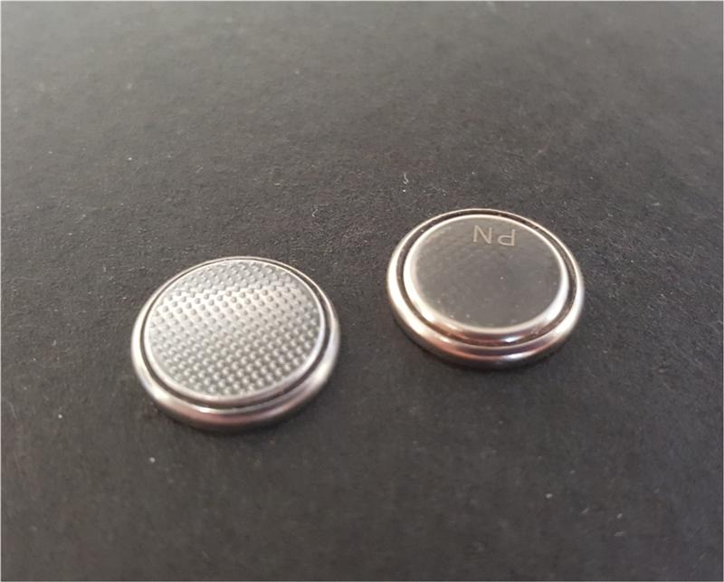
I have done some thorough testing of the battery holders on the original v0.3 boards and the new v0.4 boards and found that it’s the texture of the bottom of the battery that makes the difference. It appears that one brand of battery might have some problems making good contact with the board, but this isn’t limited to the Mayfly. I tested 3 different brands of batteries and I found that one of them is almost smooth of the bottom, whereas the other two have a bumpy texture in the metal. See the attached photo for a comparison between two of them.
What I found was that the smooth-bottom battery sometimes has trouble making good contact when inserted into the Mayfly battery socket. I inserted the bumpy-bottom battery into over 100 Mayfly boards and every one of them worked perfectly. I also had trouble with the smooth battery in a few other devices that were not made by us, so I think the problem is caused by the battery and not specifically the Mayfly board. In every case where the battery wouldn’t make contact, putting a small bit of solder on either the battery or on the board under the holder immediately fixed the connection issue.
Attachments:
See my latest blog post for information about exchanging the v0.3 Mayfly boards for the new v0.4 boards. I will also be emailing all of the Amazon customers today with information about the exchange.
Pins 10, 11, 12, and 13 on the Stalker are used by the SPIbus, so if you’re want to use the microSD card socket, you can’t use those digital pins for anything else. It’s been awhile since I looked at the specs of the Stalker, but I think there are very few free pins. That’s one of the reasons we stopped using it and created the Mayfly. And the Mayfly’s secondary hardware serial port makes it easier since you can sometime avoid using the SoftwareSerial functions if you just have one serial device to interface with.
The Mayfly boards should be available again on Amazon by this weekend.
If you measure 3.3v on the Sw_5v pin, then unfortunately you have a board with the incorrect regulator. There’s no way to get your board to generate 5v unless you replace the regulator. While it is possible to replace it if you have the right tools and you have experience removing and replacing a SOT-23 surface mount device. However, we have new boards with the correct part that we have shipped to Amazon to replace the existing inventory. I will also be contacting each customer directly through Amazon to tell them how they can exchange any affected boards for a new one.
Keep in mind that most users will not need to use the 5v setting on the Grove connector jumper. The Mayfly is not tolerant of 5v I/O signals, so any peripheral devices you connect must not send any voltage greater than 3.3v back to the Mayfly I/O pins. The 5v options is only there for experienced users who can ensure that they have proper level-shifting circuitry or other protective measures to ensure that the Mayfly only sees 3.3v signals. In my case, I use several analog sensors that need to be powered by 5v supply, but only output a 0-2.5v signal. Other digital sensors that require 5v will be connected to a level-shifting adapter board via the Grove connector.
Did you put a solder blob across the pads of P3 on the back of the board? You’re using INT0 in the code, so you need to close the pads that connect the RTC interrupt signal to pin D2, and according to the Stalker 3.0 wiki, that is accomplished by shorting out P3. I have not used a Stalker 3.0, but I know on the Stalker 2.3, the board would go to sleep after one reading and never wake up again if I forgot to short that RTC INT0-D2 solder jumper.
I’m not sure why your code didn’t post correctly. Maybe because you attached it as a .ino file. Try just pasting it into the “code snippet” box when you’re typing a reply. Just hit the “Add Code Snippet” button in the row of buttons right above the text box, past your code into the window that pops up and choose “Arduino” from the Language drop-down menu so it formats the code properly.
Here’s some code that I used a long time ago when using the Maxbotix sensors with a Seeeduino Stalker. In the example, I connected the data line of the sensor to pin D7, then just connect the sensor to ground and its power to 3v3. Communicating with the Maxbotix sensor only uses pin 5, 6, and 7 on the sensor. The sensor outputs a digital string every second when it’s powered continuously. If you only want to take readings periodically, you can power the sensor momentarily with any of the free digital pins on the Stalker since the sensor only uses a few milliamps so the Arduino digital pins can source that. In the following example, it’s powered all the time.
Arduino1234567891011121314151617181920212223242526272829303132333435363738394041424344454647484950515253545556575859606162636465666768697071/* test function to Parse data from MaxSonar serial data and return integer */#include <SoftwareSerial.h>SoftwareSerial sonarSerial(7, -1); //define serial port for recieving databoolean stringComplete = false;void setup(){Serial.begin(9600); //start serial port for displaysonarSerial.begin(9600); //start serial port for maxSonardelay(100);}void loop(){int range = EZread();if(stringComplete){stringComplete = false; //reset sringComplete ready for next readingSerial.print("Range: ");Serial.println(range);Serial.println(" mm");delay(1000); //delay 1 second}}int EZread(){int result;char inData[6]; //char array to read data intoint index = 0;sonarSerial.flush(); // Clear cache ready for next readingwhile (stringComplete == false) {//Serial.print("reading "); //debug lineif (sonarSerial.available()){char rByte = sonarSerial.read(); //read serial input for "R" to mark start of dataif(rByte == 'R'){//Serial.println("rByte set");while (index < 5) //read next three character for range from sensor{if (sonarSerial.available()){inData[index] = sonarSerial.read();//Serial.println(inData[index]); //Debug lineindex++; // Increment where to write next}}inData[index] = 0x00; //add a padding byte at end for atoi() function}rByte = 0; //reset the rByte ready for next readingindex = 0; // Reset index ready for next readingstringComplete = true; // Set completion of read to trueresult = atoi(inData); // Changes string data into an integer for use}}return result;}I’m glad it worked. We’re working on switching out all of the Amazon inventory with new boards and we’ll be testing each of them first for proper battery connections. It can sometimes be hard to solder to a battery which is why I suggested doing the board first. The next run of boards will have a different battery holder and board footprint so this issue can be avoided.
I’ve got some sketches about sleeping the Mayfly, I’ll try to post them soon. I’ve got a backlog of software examples to post, but also dealing with hardware and inventory stuff, so we’re rather busy here. It’s helpful to get requests from people so I know where to concentrate my efforts. Thanks for the heads up about the battery issue.
DaveE, did you have a similar problem with your board?
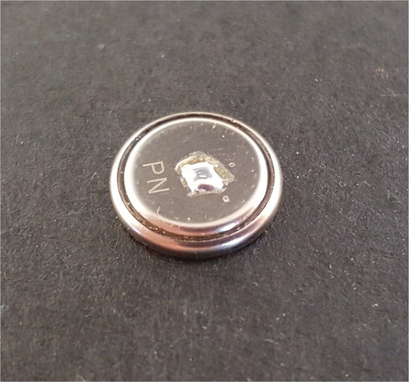
I just did some more testing with a dozen boards. Out of all of them, I found one that exhibited behavior similar to yours. It looks like the green solder mask paint is thick enough on some boards that it is preventing the battery’s negative side from sitting completely flush against the circular ground pad on the Mayfly board. You can easily remedy this by adding a very small layer of solder to the circular pad, if you have a fine enough point on your soldering iron to reach the pad without creating a solder bridge to the metal of the battery connector above it. Or you can solder a very small drop of solder in the center of the battery, like in the attached photo.
Attachments:
I just posted a helpful serial communication sketch. Try that and see if it works for you.
Some Bee modules might need additional signals or control lines to work properly. That’s why many of the Bee socket’s pins are connected to some digital pins. For example:
Bee CTS –> D19
Bee RTS –> D20
Bee DTR –> D23
Bee RI or Assoc –> A5 (via SJ7)Check the Bee section on the schematic to see how it’s connected.
That’s odd that you measure 3v on the battery alone but nothing when it’s installed in the holder on the board. Even a mostly-dead battery should read something besides 0.000v. You usually only see that if there’s a short circuit somewhere on the board (which it doesn’t look like there is, from looking at the photos), but the battery would have been drained pretty quickly, and getting quite hot in the process, and definitely wouldn’t measure at 3v separately.
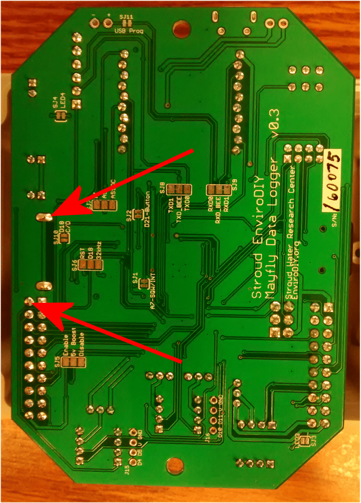
With the battery installed, measure the voltage at the two points shown by the red arrows in the attached picture. That’s the closest 2 points to the battery, so you should see something. If you’re not getting anything, make sure there’s not some tape or plastic anywhere on the battery or inside the holder on the Mayfly. Another thing to check is the shape of the battery. Is it perfectly flat on the negative (bottom) side, and if you set it down on a flat, level surface, can you tell that the battery is resting on only the negative terminal and the edges of the positive outer casing aren’t contacting the surface? What brand of battery is it? Some batteries can become misshapen or were manufactured wrong so they don’t make good contact with board in holders like these. Do you have an extra battery that you can try, or do you have more than one Mayfly board?
Attachments:
-
AuthorPosts