@shicks
Active 1 days, 3 hours agoForum Replies Created
-
AuthorPosts
-
Can you take a focused picture of just the back of the board and one of the front?
I haven’t had any problems with the Mayfly boards not retaining the time. I just tested 2 boards that have been on my bench for several months without any external batteries (other than the CR1220) and they both still knew the correct date and time. I then got out 5 new boards, inserted new CR1220 batteries, and then programmed them with the sketch you linked to, first uploading the code with the correct date and time in line 11, then commenting out line 19 and reprogramming it so the board only prints the current date/time on powerup. Leaving the boards for anywhere from 5 to 15 minutes without any external power, then connecting the USB cable, opening the serial terminal, and they all retained the correct time.
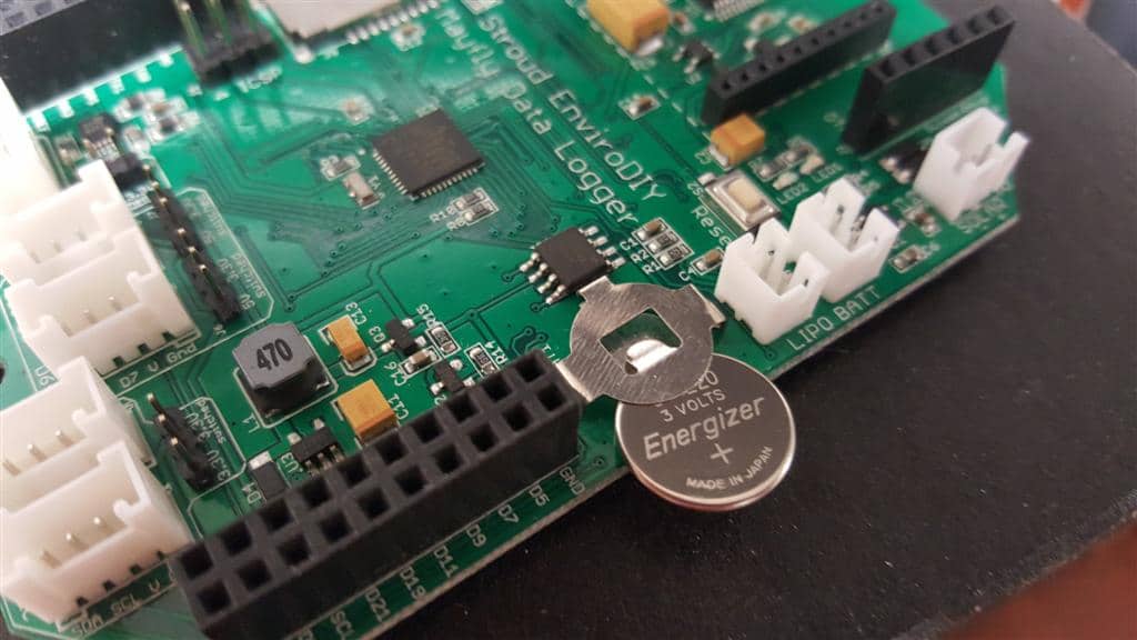
I’ve attached a photo showing the proper orientation for how to insert the battery. Double-check that you inserted it correctly. You should also check the voltage of the battery to make sure it is at 3v. The easiest way to do that is to put one voltmeter lead on the top of the CR1220 battery holder (the positive side), and use the metal housing of the main microSD card socket for the ground. You should see around 3v. If not, then remove the battery and check it outside of the Mayfly. Let me know what you find out.
Attachments:
Yes, I’ve done a variety of power measurements with the Mayfly board, so I can publish a table showing the different options. I’ll put a link to it here when the page is posted.
The Atlas Scientific sensors work fine with 3.3v VCC, so just connect the 3.3v pin on the Mayfly header (either the D22 switched or the constant 3.3v VCC pin) to the Atlas board along with a ground line. Then choose 2 free digital pins for the comms, like 6 & 7 or 10 & 11, and edit the first few lines of the sample code to change from the pins 2 & 3 that’s shown in the demo.
If Windows doesn’t find the drivers automatically, you’ll need to install them manually. I just installed the drivers on a dozen new Window 7 machines and WindowsUpdate was able to find the correct driver each time. The FTDIchip.org site has instructions for how to do that. Note that there are 2 different drivers that need to be installed: one is the FTDI drivers, and the other is the virtual com port (VCP). If the installation failed or didn’t go properly, the FTDI website has some instructions for how to update the drivers manually. If you check DeviceManager, do you see the virtual com port listed or any warnings under the ComPort or USB sections?
Another alternative is if you already have an FTDI device, like the Adafruit FTDI-Friend, the Sparkfun FTDI Breakout, or a cable with built-in FTDI, and you’ve used it with other boards, then just use that to program the Mayfly via the FTDI header.
Try this DHT sensor example. It shows you how to power the switchable Grove connectors, and you can just replace the DHT stuff with some SoftwareSerial code to use either the D6-7 or D10-11 pins for the serial comms.
Or you could use the D4-5 connector, the default jumper sets it to 3.3v constant. The D6-7 and D10-11 sockets are always switchable, either 3.3v or 5. Only experienced users should use the 5v option, since they will need to insure that the sensor or other peripheral device is either one-way or has level converters so that the higher voltage required by the remote device won’t get fed back to one of the Mayfly digital pins.
Thanks for the information JimMoore. I’ve personally used several dozen of the microUSB cables from that same shipment and haven’t had an issue with any of them, but we’ll make a note of it for future orders. I checked out the board that JohnSmutny had the issue with and it was indeed a bad mechanical contact inside the slide switch that caused the intermittent problem, but only on the pole that controls power to the FTDI circuitry.
Yes, if you’d prefer to use the hardware D10 interrupt, just cut the trace and solder a jumper over to the D10 pin on the header row. Then you can use “INT2” as the interrupt.
The Mayfly has 3 hardware interrupts, D2, D3, and D10. Since the first two are part of the serial UART, that only leaves D10 as the only available hardware interrupt. On the Mayfly v0.3 board, the RTC is connect to A7, so you have to use a “pin change interrupt” library to handle an interrupt from something other than one of the hardware pins. This can also be helpful if you’re looking for a trigger signal on any input pin.
The SODAQ pin change interrupt library works great for this: https://github.com/SodaqMoja/Sodaq_PcInt
You can also read more information about how SODAQ handles the interrupts on the Mbili, which is similar to the Mayfly. http://support.sodaq.com/interrupts/
I’m working on some sample Mayfly code for handling the pin change interrupts, I can hopefully post it soon, but the SODAQ links should help you in the meantime.
John is right, just about any sensor you find should be able to work with the Mayfly, though you might have to add some interface circuitry or adapters depending on the power requirements and communication protocol of the sensor. I’ve got Mayfly board working with digital output sensors (either TTL, RS232, or SDI-12 outputs) and analog output sensors, and I’ll be posting code examples soon. It’s also possible to use 4-20ma output sensors if you have an interface, but we don’t currently use them in any of our active projects so maybe someone else can chime in with their experience with using 4-20ma sensors.
As for the types of sensors, we normally use research-grade high-quality sensors for turbidity, conductivity, pH, dissolved oxygen, etc. While the cost is relatively high compared to the low cost nature of the Mayfly, we prefer them because of their precision and dependability. We are also experimenting with different low cost sensors for measuring those parameters and hope to have some results to share later this summer.
-
AuthorPosts