
Home › Forums › Mayfly Data Logger › Monitoring power consumption
Tagged: power; solar; battery
- This topic has 42 replies, 5 voices, and was last updated 2024-02-23 at 2:43 PM by
 neilh20.
-
AuthorPosts
-
-
2020-09-29 at 1:37 PM #14611
I’m wondering what techniques people have used to monitor power consumption by their Mayfly installations in the field. On the desktop, I suppose you can measure the current being drawn from the battery by using a multimeter, though I haven’t done that yet. And you can measure the current drawn by a sensor during its operation as well. Ideally, it would be great to be able to have the Mayfly itself take these measurements and report them as a variable. Is that even a realistic idea?
I have a couple of use cases for this idea. We have stations in the field that we suspect are consuming more than usual power due to marginal cell signal, but it would be nice to know what they are actually experiencing under field conditions. Second, as we investigate new sensors to try, it would be nice to be able to field test them under various conditions and to be able to monitor their current draw over time.
I’ve done this kind of measurement on solar power systems using a shunt to calculate and log net power use (charging minus draw), but I don’t know whether it’s feasible to have a microcontroller like the Mayfly to monitor itself as I’ve described.
Hope this makes sense!
Matt
Trout Unlimited
-
2020-09-30 at 11:52 AM #14613
It looks like this power sensor from Adafruit could work: https://www.adafruit.com/product/4226
This sensor, with accompanying library from Adafruit, returns milliamps, millivolts, and milliwatts via I2C, so seems promising.
This is new territory for me, so if anyone has insights or advice, I’m happy to hear it!
Matt
-
2020-09-30 at 1:20 PM #14614
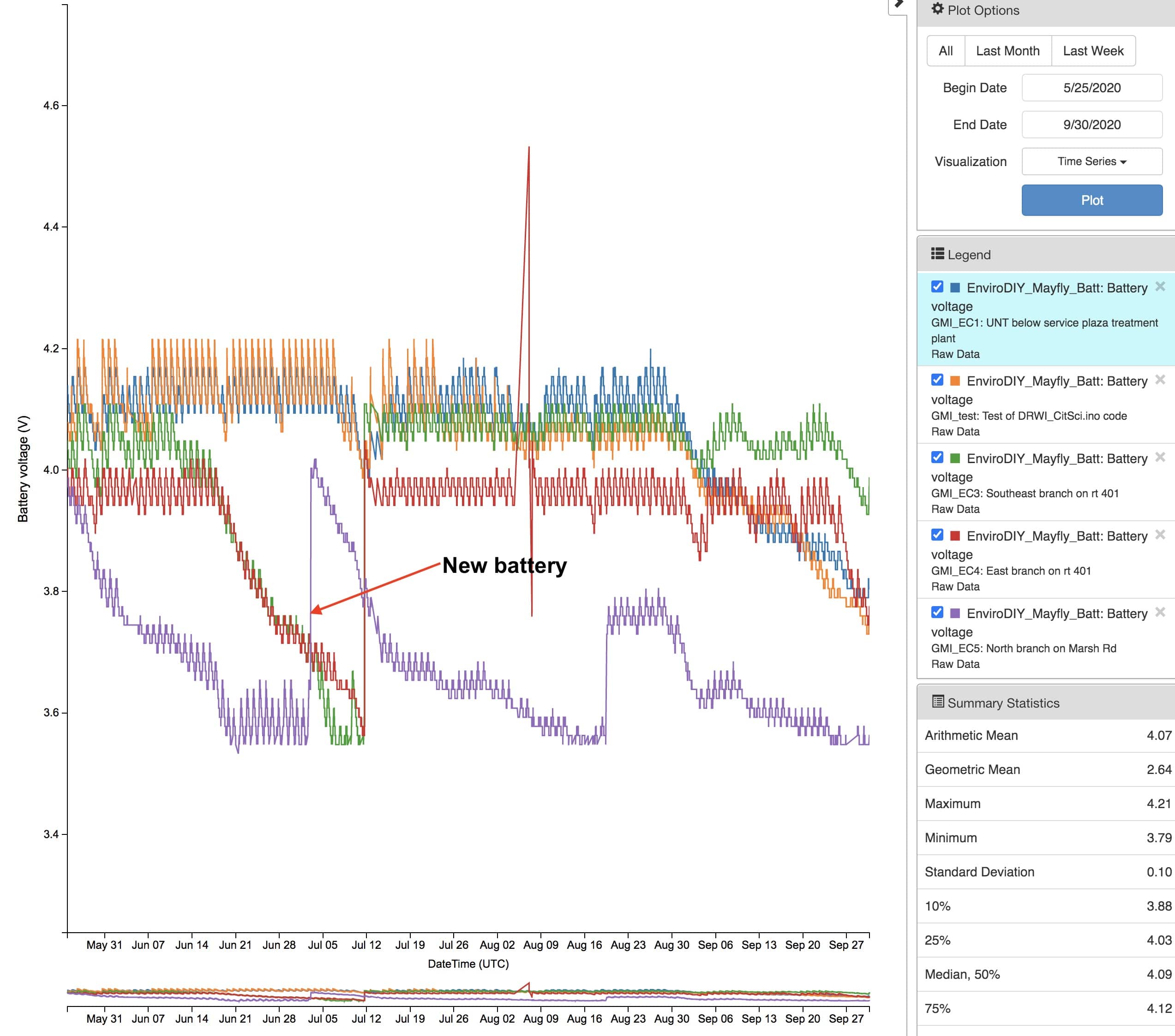
I have the same issue. I have my LEC stations (GMI_ECxx) running with 2G cell service and I did have one station that the solar charge chip failed and caused battery to drop below the 3.55 volt threshold for upload. However GMI_EC5 seems to be getting a charge during the day but is still not keeping up. I attached a screen from MMW TSA and you can see the drop-off in voltage on this sensor station vs the others. I also noticed a general drop off which I presume is amount of daylight. I am using the 2.5 AH batteries. I plan to check current draw to see if it is abnormal or caused by poor cell service.
Attachments:
-
2020-10-01 at 2:56 PM #14619
Interesting, thanks Jim. I’ve been wondering whether one of our problem stations has a charge controller chip that’s impeding its charging, so we’re preparing to swap out the Mayfly to troubleshoot.
-Matt
-
2020-10-01 at 5:57 PM #14623
I checked my GMI_EC5 station that I mentioned above that was not keeping up and I measured about 2.4 mA current draw when the mayfly is in sleep mode. I thought it should be close to zero when in sleep mode.
Any thoughts Shannon?
-
2020-10-05 at 10:47 AM #14629
Without having been to that station myself, it’s hard for me to guess why that station is having more battery trouble than your other ones. I’m guessing maybe it’s more shaded, or possibly the solar panel isn’t pointed in an optimal direction? You could also try putting a voltmeter on the panel on a sunny day and make sure it’s putting out around 6v (or even better, put an ammeter in line and read the charging current). We’ve had a couple of panels fail over time and don’t provide enough power to fully charge a battery. We’ve also seen issues where the charge controller circuitry on the Mayfly would partially fail and cause it to default to the trickle charge rate instead of full current charge. We’ve also had malfunctioning GPRSbee modules that tend to drain the battery power quicker even when asleep. I’ve also seen problems with microSD cards that start to go bad and draw excess current when the Mayfly is supposed to be sleeping.
So I’d say check your solar panel voltage, remove your GPRSbee, and replace the microSD card. If none of those fix the issue, put a new Mayfly in there. If the battery levels still fall, then replace the solar panel. If none of that solves the problem, then it’s likely just a shady location. If you’ve got deciduous trees around the station, sunlight should be improving in the coming weeks as the leaves fall, so that may also affect your results. We have a few stations that always struggle to stay charged during summer because of the full canopy above them, but they do great the rest of the year, even in the winter when the sun angle is lower.
-
-
2020-10-06 at 10:53 AM #14631
Thanks for the info Shannon. I will check out the GPRSbee and sd card to see if they are the cause of the 2.4 mA draw when in sleep mode. I’ll try a new Mayfly board next.
-
2020-10-08 at 4:36 PM #14656
I’ve been using the INA219 and contributed sensors\TINA219
I’ve used it for measuring a working Mayfly on the lab bench. For field monitoring, I would think you need a coloumb counter ~ eg LTC2941 ~ I have an adafruit version but haven’t tried it.On the lab bench I have the INA219 on a separate Mayfly with console and put in in series with the target systems LiIon battery.
https://github.com/neilh10/ModularSensors/wiki/Test-equipment-cable-monitor-LiIonFor measuring a working Mayfly current I disconnect all other sources of power, and even have a special version of the FTDI cable to plug into the FTDI debug (instead of USB data/power) with the Ftdi Tx cut (as its held high and leaks current)
https://github.com/neilh10/ModularSensors/wiki/Test-Equipment-FTDI-cableUsing this arrangement, sampling every 2secs to get an idea of the instantaneous current
https://github.com/neilh10/ModularSensors/tree/release1/tools/current_loggingThere has been past discussion on Mayfly sleep current. IMHO I’ve got to be in reasonable shape, but perhaps not meeting what a calculated minimum suggests it could be. https://github.com/EnviroDIY/EnviroDIY_Mayfly_Logger/issues/21
I figured for reliability of systems in the field a software based Battery Management System was more viable than trying to tweak down the sleep current. The target is reliable data collection, and reliable delivery for low cost LiIon/4Ahr battery and solar panel/5W. Note the Mayfly Vbat monitor becomes non-linear at about 3.6V
The figures I got for Mayfly sleep was 2~4ma. I have some notes that when I started taking measurements it was about 5mA. I did some tweaks got it down. Here are the measurements I made in my log with a Digi Xbee WiFi.
<h3>2018Dec12 sleep Current readings</h3>
with INA219 monitoring from another Mayfly
1st time through from RESET
02:13:24.972 mA: 3.80, V: 0.908
02:13:26.971 mA: 1.90, V: 0.936
02:13:28.972 mA: 2.10, V: 4.048
02:13:30.973 mA: 7.70, V: 4.044
02:13:32.972 mA: 4.00, V: 4.048
02:13:34.999 mA: 3.60, V: 4.048
02:13:36.999 mA: 38.20, V: 4.020 <sensors starting02:13:38.999 mA: 38.20, V: 4.024
02:13:40.999 mA: 38.20, V: 4.020
02:13:42.999 mA: 38.20, V: 4.020
02:13:44.999 mA: 38.20, V: 4.020
02:13:46.999 mA: 105.30, V: 3.972 <1st time Xbee including setup
02:13:48.999 mA: 90.00, V: 3.972
02:13:50.999 mA: 107.20, V: 3.968
02:13:52.999 mA: 106.80, V: 3.968
02:13:54.999 mA: 107.20, V: 3.968
02:13:56.999 mA: 106.70, V: 3.968
02:13:58.999 mA: 53.80, V: 4.000
02:14:00.976 mA: 107.50, V: 3.964
02:14:02.977 mA: 121.90, V: 3.964
02:14:04.976 mA: 106.80, V: 3.960
02:14:06.977 mA: 106.80, V: 3.964
02:14:08.977 mA: 106.40, V: 3.964
02:14:10.976 mA: 121.10, V: 3.960
02:14:12.977 mA: 106.60, V: 3.956
02:14:14.978 mA: 107.40, V: 3.956
02:14:16.979 mA: 3.60, V: 4.028 <off sleep
02:14:18.978 mA: 3.60, V: 4.032
02:14:20.979 mA: 3.60, V: 4.032
02:14:22.980 mA: 3.60, V: 4.036
02:14:24.978 mA: 3.60, V: 4.03 -
2020-10-08 at 4:56 PM #14657
I should note, that for real world solar panels, the power supplied by the panel is dependent on the solar photons received. For a slow change in power delivery some circuits have some strange behaviour. I’ve had a Mayfly with an LTE module, and a 2Ahr battery, and at sunset it started resetting. It continued resetting for about 30minutes until the sun’s power was completely gone. I had let it run and this repeated every night for a week. I changed out for a 4Ahr battery and the resetting stopped. The 2Ahr battery was being fully charged every day, and when the sun was down it ran OK overnight – just in the twilight zone it had a problem. Was OK with sunrise.
I was monitoring the LiIon battery voltage with both the Vbat ADC and also externalV with 100K-100K divider. The Vbat ADC was showing a funny dip in voltage before it reset – but I never investigated further – just made sure I used the 4Ahr battery. I am doing some characterization work how to measure a battery that is below 3.7V – but still ongoing.
-
2020-10-09 at 4:47 PM #14663
Thanks for sharing this good work, Neil. This does get technical, and I have a lot to learn, but your experiences will be helpful. For the short term, our team is primarily interested in knowing approximately what the limits are, for a given site, for a given set of sensors, whether the available solar power will keep our stations running for the site-specific constraints. Larger panels and batteries are a potentially cheap solution, relative to my R&D time, though Issue#23 describes the existing limitations of the Mayfly circuit’s charging current, which I was not aware of until just now. We’ll have the option (usually) to reduce sampling frequency to save power. Another avenue for power savings might be to implement 2 Loggers: one that logs frequently to the SD card, and one that runs less frequently to transmit via cellular, which can be a high drain, as I understand it. Just thinking out loud.
-Matt
-
2020-10-09 at 8:36 PM #14664
Hi Matt, power is a challenge. I always think of those battery watches with a tiny battery in them. How do they do it.
My take is this. a) what is the minimum energy its going to collect across the really low solar months eg winter months b) What is the longest I want the system to run for with no solar power – that is usually a storm of some sort.
Then the stored power can be budgeted into two sections – one for the time period that it needs to be working/sampling to run with no solar energy input, 2) when there is “excess” energy that can be used to transmit the readings to the cloud. An assumption in this is of course that the readings will be stored (on uSD), and when there is available energy can be reliably delivered to the cloud . (https://github.com/EnviroDIY/ModularSensors/issues/194)
The current Mayfly charging circuit assumes a relatively low impedance on the solar side, and for all practical purposes its easy to over specify the solar panel to 5-10W (for Mayfly) so it is likely to delivery the 0.5A at 4.5V when ever there is solar power there. For a 4Ahr battery, it would be charged in 8hrs ~ a summers day but in winter?
On the consumption side – I’ve put a spread sheet together in mA-secs or mA-minutes to estimate usage. So using mA/minutes a 4Ahr battery has 4,000mA*60minutes – 240,000mAmin.
For 24hrs if sampling is every 15minutes and takes 0.5min of running current – say 38mA and the other 14.5min are at a sleep current of 2mA. Then every 15min it consumes 38*0.5+2*14.5 or 17+29 or 46mAminutes – and in a day – 96 sampling periods ~ would take 4,416mAminutes. So for 4Ahr this would likely last over 54days without any solar power. However with the battery power “budgeted”, if the 4Ahr can be divided into 2Ahr for communications and 2Ahrs for guaranteed core taking readings then using 4,414mA it would have 27days.
I’ve created a Battery Management System to be able to partly implement this in a “simple” way. Yet to be entirely proven. The basic premise is that at critical points in the program a call to the BMS asks is there enough power for the operation to be performed? One of these points, after wake up is to check if there is enough power to transmit readings. If the answer is NO, it just does logging, if Yes it does LoggingAnd Transmisson. (Uses the current Class entry points)
So far I haven’t considered the power cost of transmitting the readings to the internet, as its expensive in power, but this would only happen when there is enough power. So a separate budget power exercise needs to be performed for the cost of transmitting, but it can be gated so it only does it when there is sufficient power (for a winter that might happen after the sun has risen enough to be charging the battery).
In practice the LiIon voltage is partly dependent on ambient temperature (cold in winter), and Mayfly mega1284 Vref tied to Vcc at 3.3V, and combined with charging/Solar input. So Vbat does not reflect LiIon battery at all times. So for NO solar the Vbat ADC results are accurate from 4.2V to about 3.6V, when it becomes non-linear due to power cct LDO dropouts. For ~~good~~ solar the Vbat ADC reflects how well the battery is being charged and is likely above 4.2V ~ mostly not a problem. So hopefully the Vbat absolute voltage could have a number 3.8V? (…. 3.9V) that is crudely interpreted as a 50% (or 75% ) “fuel gauge” for a reasonably large LiIon battery. The problem may be when there is weak solar, and when the Vbat absolute readings are taken may indicate a solar charging voltage, that doesn’t reflect the power stored in the battery. The Modem takes power at different time than when the Vbat ADC reads the LiIon voltage ~ so there could be nonlinear Vbat readings just at the most needed time when the LiIon is run down. That is with a weak solar charging current the Vbat is the solar charge voltage, not the LiIon battery voltage. I’ve been investigating a separate battery monitor on the external ADC, and potentially also the Xbee LTE’s has a voltage converter that can measure the Vcc (which should be ~ 3.3V).
https://batteryuniversity.com/learn/article/discharge_characteristics_li
For being able to do shorter time period testing I’ve been using a 500mA hr battery for testing the BMS transition thresholds, and I’ve built in an option for different types of batteries 2Ahr ..4Ahr with different thresholds.
Well hope its not too much detail, but I’d be interested if this going in the direction you think might answer your questions. 🙂
-
2020-10-15 at 6:37 PM #14670
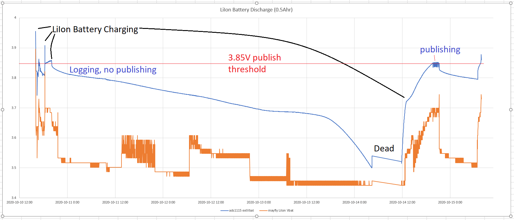
I’ve had a simple system soak testing. Its not meant to be a deployable system, but I’m using it for testing out powering related algorithms.
It has an Xbee WiFi, LiIon 500mA, measuring MayflyVbat and ADS1115 extVbat. When the extVbat voltage is >=3.85V it will
Logger dataLogger.logDataAndPublish();
and when below <3.85V only
Logger dataLogger.logData();
I’ve used the 3.85 threshold as I found the Mayfly was resetting when the WiFi turned on and LiIon battery was around 3.7V.
For the “Solar Panel” I’ve got it connected to a power supply and simulating low sunlight conditions with a charge typically round 25mA.
The graph of this running since Oct 10th is
Attachments:
-
2020-10-24 at 7:06 PM #14711
I’m sharing some integration test results. I’ve been using a Vbat=4.0V threshold – that is under Vbat=4.0V it does sensor readings only, and stores the readings for later reliable data delivery.
When the battery voltage is over Vbat=4.0V it POSTs the readings to MMW.

A feature of using 4.0V is that probably works for the Mayfly Vbat measurement, and really extends the effective life of the battery when there is no solar. A wrinkle is that a lot of readings can be stored, which could exhaust the available power in the battery if all transmitted in one shot. So when a connection is made after X(default=10) retransmission of POSTS from the FIFO file, it checks the battery again to see if it is still over 4.0V.
These are all on my “rel1_dvlp1m” branch – https://github.com/neilh10/ModularSensors/tree/rel1_dvlp1m – and I’ll plan to describe it and make a release in the near future.
-
2020-11-19 at 2:35 PM #14847
Continuing some ideas on https://www.envirodiy.org/topic/battery-capacity-fuel-gauge
-
2023-11-26 at 6:42 PM #18181
We have the standard Mayfly kit from TU…the sun here in the winter is apparently never strong enough to charge the battery with the default solar panel and battery. The voltage reading may get to above 4V for a short time (maybe 1 hr per day), but quickly drops and no more data is transmitted. I dont know if the voltage i see is coming from the battery or from the solar. I don’t know if data is getting saved on the sd card.
I checked one station last week and the board was flashingall sorts of green and red lights. The clock is wrong too.
A bigger solar panel is something we could install, and perhaps a bigger battery. In one location we are in an old guaging station so battery size is no issue. In another location we’d need to have it fit in the otterbox or we could setup another small enclosure for the battery.
I was also thinking about using 8 AA’s like in a game camera. Those energizer lithium last forever…but if there is a constant current draw with the Mayfly then they may not be the answer.
Any suggestions for a location (47-48 degrees N) with very little good sun and avg daytime temps 35 in the winter?
-
2023-11-27 at 11:51 AM #18184
@jp thanks for sharing – power is a challenge when there isn’t enough of it. Finding enough power for your systems is the easiest step, – that is upsizing the solar panels, and ensuring they have enough solar aspect this time of year.
Just wondering, what is the standard kit that you have and source- sounds like you have the Mayfly 1.1 – what is the solar panel ? and battery ? and/or sensors
Cycling green and red leds is usually an indicator that its continually going through reset, Its NOT getting enough power to complete startup and then probably fails when invoking a heaver user – probably the modem. In short, IHMO, the ModularSensors architecture doesn’t do power demand management. That is it assumes there is enough power to get through the power up stage. I’ve talked about it extensively and come up with my own software to handle edge “reliability conditions”, and is available for anybody to use. https://github.com/neilh10/ModularSensors/wiki/1a-Feature-notes
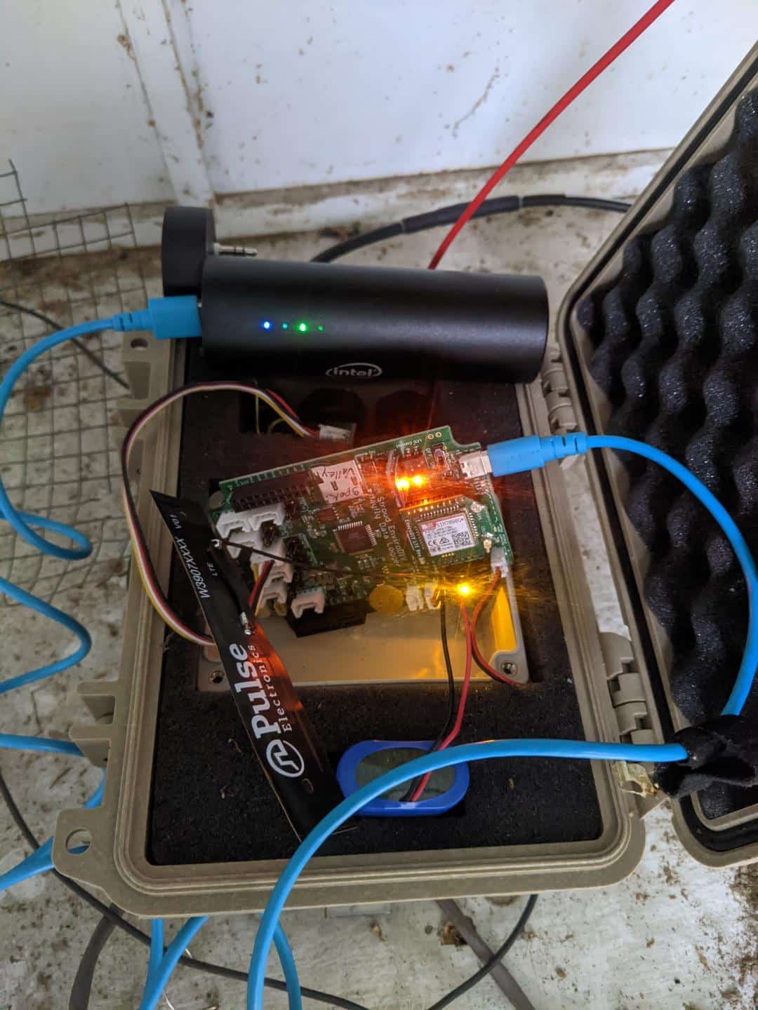
An easy fix, if you are visiting the site, is to take a USB power pack with you, and then with an appropriate cable (Mayfly 1.x is USB-C) plug it in and boost the local Lithium Ion battery. However this can take a couple of hours, and the USB Power packs I have turn off when full charged the local battery, and then never turn back on – until unplugged.
This is a good conversation to have, so please share the details.
-
2023-11-28 at 11:45 PM #18189
Hi thanks for responding. I’m sure our system is undersized for our location. Today was a pure sunny day, last week we installed an extension pole and cable so the solar is up plenty high to get direct sun. But today we got no readings sent via cellular.
Our battery is a LiPO 4400mAH 3.7V.
The solar panel is a 1W 6V
Open Circuit Voltage: 7.7V
Peak Voltage: 6.5V
Peak Current: 180mA
Peak Power: 1.2WTrout Unlimited’s guide says that any reading above 4.0V is a fully charged battery. But this winter we’ve seen the reading above 4 and an hour later no more data. So it doesn’t seem like the battery is truly fully charged because it would last more than an hour.
If anyone has a recommendation on the max solar panel and battery I’d appreciate it. The other option which I think would work is to get a pack that holds 6 or 8 AA energizer lithiums and use that, but we would need to program the mayfly to not draw any juice until reading the meter or transmitting data. And we could maybe set it to send every hour instead of every 15 minutes. I’ve had game cameras sit out all winter and take hundreds of pictures and videos without draining those energizer lithium batteries. I don’t know what a game camera draws while not taking a picture, I know the clock stays accurate.
Thank you!
James -
2023-11-29 at 7:05 AM #18190
What version of Mayfly board do you have? And what brand of cellular board? There are a lot of combinations of hardware on EnviroDIY stations, and some are much more efficient than others. Also, do you have a spare Lipo battery that you can fully charge separately in your office and then put it into the station? If your logger is only working when there’s sunlight, then it’s pretty likely that your battery is faulty and won’t charge, that’s why it’s not providing power overnight.
-
2023-11-29 at 1:26 PM #18192
Hi @jp – I only install 2.5W or for a shady location I upgrade to 10W. Can you share the site that is publishing on, and can see how fast the power went down.
The non recharge batteries could work – but you need to do a lot more power calculations to understand how long they will work. 4 batteries (4*1.6V =6V) will work for a boost plugged into USB-C, or a special connector instead of the Li-Ion – but then you need (3 * 1.6V = 4.8V) … , and probably D cells better options
My first suggestion is for you to get a USB Power Pack and just recharge the internal Li-Ion – I purchased this option a 10AHr USB, “10000mAh Dual USB Portable Charger, ”
and with a USB C cable plugged it into the Mayfly 1.1 – that recharged the LiIon battery in 2 hours
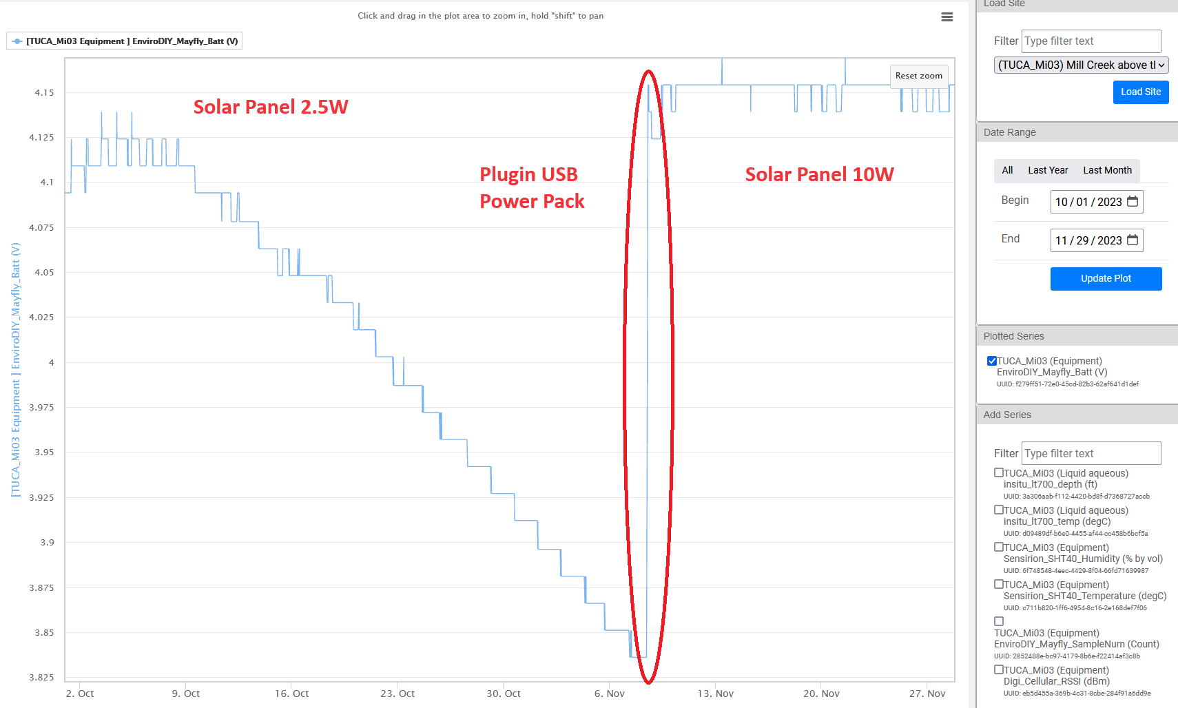
See https://monitormywatershed.org/sites/TUCA_Mi03/ battery Voltage – from Oct 1st. With the change in season there was less solar its deep in a Redwood forest The voltage declned from 4.125V and to about3.83V. At 3.8V my software stops it from transmitting readings. I was on site Nov 8, and plugged in the USB Power pack at 11:30 and it fully charged the 4.4Ahr battery by 13:00 – 90minutes. Then I also upgraded the panel to a 10W panel.
This was the context of the system. I align the solar panel to SW, but there was a lot of trees at that aspect, and with winter the solar aspect was decreasing.
https://photos.app.goo.gl/HMi5TDmh6n2rYdzA6
Though after the above I moved the solar panel to 15′ away, and then upgraded the 2.5W to 10W solar panel – which gets enough dappled ambient for an hour or so to boost the battery enough
Attachments:
-
2023-11-29 at 2:19 PM #18194
Thanks for the data, Our site has much more exposure to sun than in a redwood forest, and is doing something similar:
https://monitormywatershed.org/sites/SpokaneR-SpokaneValley/Note the times on the website are accurate but when you look at the data the times are not accurate — sun isn’t up at 5am. I wonder why the clock reset..
The last transmit via cell was 2:45 pm on 11/27. Yesterday Nov 28 was a full sun day all day…so it seems that that solar panel doesn’t run anything, all it does is charge the battery, and the battery never got charged enough to transmit via cellular.We have version 1.1 boards.
The cell module says SimCOM – SIM7080G, P/N S2-108HB-Z308J
Our only sensor is a Hydros 21 CTD.It sounds like the bigger solar panel might do the trick. I also saw in another discussion going to a 6600mAH battery. So this panel https://voltaicsystems.com/10-watt-panel-etfe/ with this battery https://www.amazon.com/dp/B0137IPVY6. And get the battery charged at home via usb before bringing it out into the field.
Though for the good of the order I wouldn’t mind also trying 4 AA 1.5v energizer lithiums into the usb port and see how long they last. Something like this https://www.amazon.com/dp/B08P1L6JQT with a usb adapter https://www.adafruit.com/product/4536.
-
2023-11-29 at 11:56 PM #18195
deleted and restated below
Attachments:
-
2023-11-30 at 1:48 PM #18197
(previous post deleted and restated) @jp – interesting data. It very much looks like up to early October the solar was delivering enough power for the system.
Then with the seasons solar changing, the solar panel aspect is not delivering the power needed
What I would recommend is a) need to charge up the internal LiIon 4.4Ahr battery
- b) try and get more solar power
for a) my choice is the plentiful USB battery pack which can supply at least the 4Ahr at 5V. Your choice of Lithium primary batteries is also good – Li Primary have a good discharge characteristic – meaning 4 batteries at 6V would supply most of their power before dying. Alkaline and standard Carbon Zinc decay to about half the voltage when supplying their current.
However the AA Alkaline are rate at 3Ahr so probably a good boost to a partially dischatged 4.4Ahr battery
b) So anything you can do to help out a better solar aspect – less shade would help, and solar panels are best set at an optimal 45 degress or more from horizontal, but depends on the type of solar bracket. Winter sun is the more challenging, so best optimized for that – but I haven’t had much luck with low cost brackets to be able to do that.
An upgrade of the solar panel that is under 10V open circuit and at least 2.5W ~ another option https://voltaicsystems.com/3-5-watt-panel/ and of course the range https://voltaicsystems.com/small-solar-panels/ And also some same manufacturer here https://www.adafruit.com/product/5367
I’d be interested in what the software that you are using,
Particularly see what it thinks it is doing with low battery V – which results in what I’ve labeled as “Unmanaged Power Demand”. Its pretty amazing it still manages to get enough power to broadcast over the modem. The .csv file from the uSD would tell more of a story of what is happening when it resets.
This would be my analysis of the battery voltage readings from the site
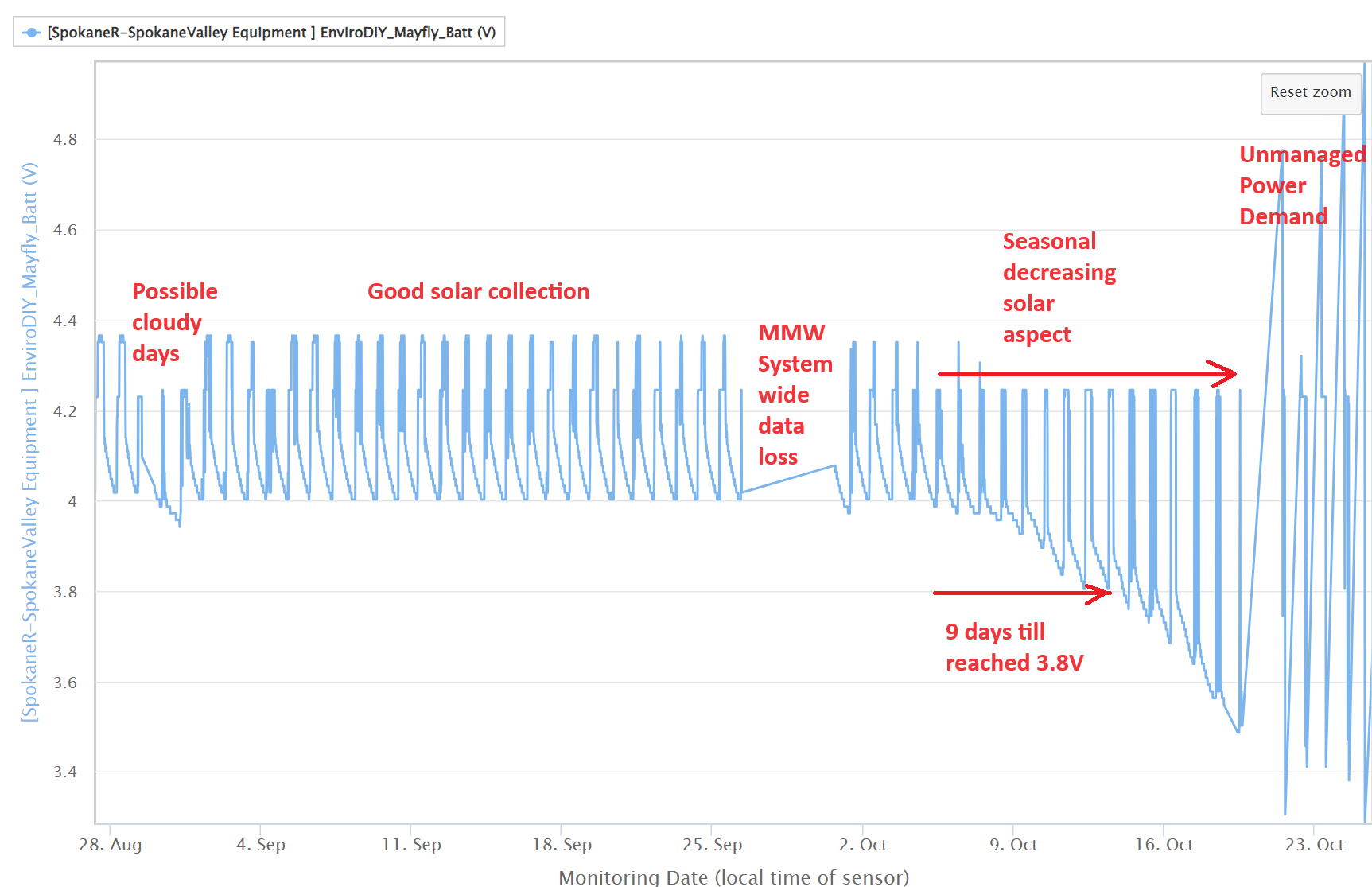
<p style=”background: white; vertical-align: baseline; margin: 0in 0in .25in 0in;”><span style=”font-size: 10.5pt; font-family: Roboto; color: black;”>(I’m still analyzing my systems as to the gap that I’ve labeled “MMW System wide data loss”)</span></p> -
2023-12-01 at 11:15 AM #18200
James, your station seems to be using power at a rate much higher than a usual CTD station. Our Mayfly v1.1 boards with EnviroDIY sim7080 LTE board and a CTD sensor will see a decrease in the battery voltage overnight of 0.045v during a 12 hour period with absolutely no sunlight, and transmitting the data to the portal every 5 minutes. Your station seems to use at least 0.15v overnight, so that’s indicates the board is probably not sleeping or has some other thing that is drawing more power than the solar panel can replace the next day. And if your Mayfly’s clock is wrong, it sounds like the CR1220 coin cell on the board is dead or installed incorrectly. It should retain the proper time for multiple years, even if the main external lipo drops out due to bad charging. When a new, charged battery is connected to your Mayfly, is the green LED next to the power switch turned on constantly? For logger deployments, it should be deactivated by turning off the small DIP switch next to the LED as described in the EnviroDIY monitoring station manual. And if there’s something incorrect with the Arduino code of the logger, it can prevent the board from going into sleep mode between readings, at that could be the reason for your excessive power usage. It looks like all of the stations in Spokane are behaving the same way and using more power than normal.
-
2023-12-01 at 12:34 PM #18203
@shicks I agree it would be good to see the software. For my systems I look to have it last 14days before it reaches 3.8V and it is a difficult target unless its being tested for and the time taken on the radio is also characterized.
I see the issue is how to keep the sensor readings delivered reliably while there is enough power, and then when there isn’t enough power to manage the processor reliably until there is enough power – usually when harvested from solar.
I wonder what you see as a valid range for the Vbat, – some readings in the “Unmanaged Power Demand” indicate 5.1V and 3.0V. Can they be valid? For the recommended Adafruit 4.4Ahr battery, with a cellular comms SIM708, what thresholds do you see should be used?
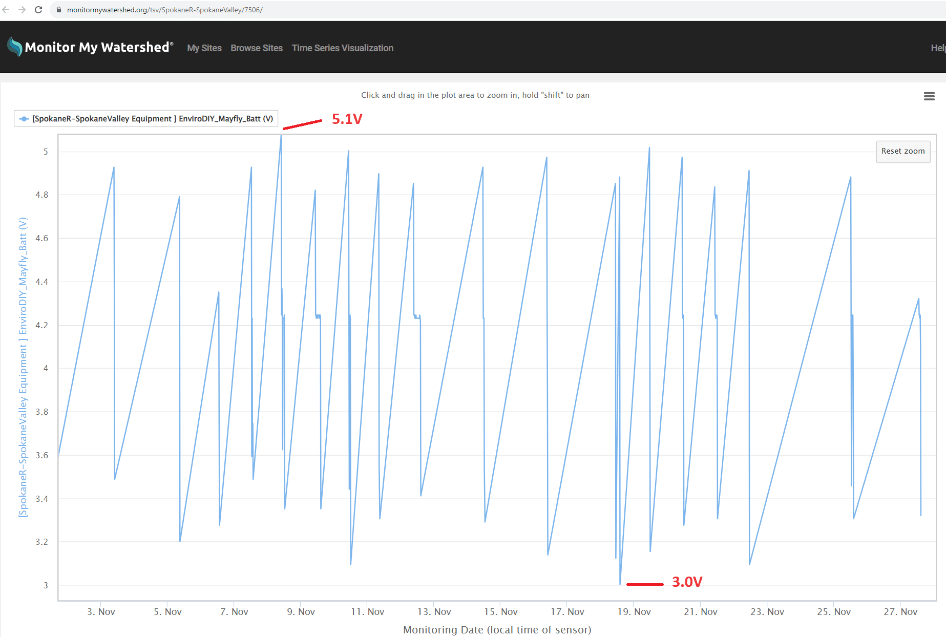
This was what I used to guide my algorithms to avoid resets https://github.com/EnviroDIY/EnviroDIY_Mayfly_Logger/issues/32#issuecomment-959807618
and of course I implement the reliable software delivery
Attachments:
-
2023-12-01 at 6:30 PM #18208
I don’t believe any lights are on during the 15 minutes between data transfers. In the summer and fall lights would start blinking every 15 minutes, then stop for 15 minutes, etc. I’m not sure if there was something happening during the 15 minute break. Once I get the battery charged up with a powerbank i’ll check the dip switches.
Crazy, today at 1:30pm the battery voltage read 4.958. 15 min before that nothing, after that nothing. It’s been cloudy and snowing all day.
I don’t understand how the battery voltage could go from low to max to low again in 30 minutes….could something be going on that would drain the battery in less than 15 minutes? The last time i was out there i opened the otterbox and it looked like every light was randomly blinking, nonstop. But after I reconnected the solar panel that didn’t happen.
-
2023-12-03 at 2:28 PM #18209
If your sample/transmission rate is set to 15 minutes and you were getting that poor of a battery life out of your stations, then they definitely aren’t going into sleep mode, so I’d suggest investigating the code that’s running on the Mayfly to learn more about its behavior.
-
2023-12-04 at 1:25 PM #18210
@shicks surely the issue isn’t how long it lasts – it will always run out of power at some point, or even worse batteries loose capacity, what was working decays – the issue is how to reliably recover when it has run out of available mA. ?
The reliable bit – as in all engineering – is to add a buffer for real world component variations and that it just works for the “large power demand” when the modem turns on – across the expected usage of the battery. When Li-Ion batteries run down, their impedance goes up, they can supply less current at that voltage, and they need special charge management while they acquire a minimum charge .
-
2023-12-12 at 5:54 PM #18229
I wrote the same code for all of the Spokane stations. Compare the battery behavior for SpokaneR-SpokaneValley (poor) to that of SpokaneRiver-Peaceful (good), despite running the same code.
I’ll attach the code for both stations.
-Matt B.
Attachments:
-
2023-12-13 at 8:51 PM #18237
Matt Thanks for posting. I’m away from my computer till next week, so I’ll be interested to look when I get back.
Seems like SpokaneRiver-Peaceful has good solar, and the battery never gets low. -
2023-12-15 at 12:22 PM #18247
Yesterday I attached a powerbank to the usb-c port for a little over two hours. Two yellow lights were on, one near the usb-c port and one lower down. I also installed a 10w solar panel. When I detached the powerbank, the yellow light near the usb-c port turned off but the other one stayed on. The station held voltage for two hours after that, then dropped to 3.5v volts.
Does anyone know what that other solid yellow light is for? Would like it to not be on and drawing power, unless it’s the “solar charging happening right now”” light.
I am thinking about pulling the unit, bringing it home and charging it with a phone charger (5v 2A) overnight. Maybe my powerbank didn’t quite get the battery over the hump. It’s older and probably not a ‘fast’ charger.
Attachments:
-
2023-12-15 at 12:39 PM #18250
A description of the operation of the LEDs on the Mayfly board can be found here: https://www.envirodiy.org/mayfly/hardware/details-and-specs/
For the one you asked about, it’s under part C:
C- Power LEDs and DIP switches: LEDs indicate board power (green) and USB power (orange). Useful for easily seeing if the board is on and if USB power is connected. Green LED will be lit anytime the board has power and the power switch is in the ON position. Orange LED will be lit anytime power is being supplied through the USB or FTDI connectors. If Mayfly board is deployed in a sleeping logger station, it is recommended to set both DIP switches to the OFF position in order to save battery power. Use a small pointed object to gently slide the small white squares of the DIP switch either to the ON or OFF positions.
Have you tried replacing the battery back on the station with a fully charged one? Sometimes the Lipo packs won’t take a charge or charge properly and just need to be replaced with a new one.
-
2023-12-15 at 1:07 PM #18252
Thanks! So the yellow light was on because solar was charging, that’s good news. I assume that light is powered by the sun and not the battery.
Our next step will be to replace the battery if the full overnight charge doesn’t work. I’ll set those two DIP switches to off after I try to fully charge the battery.
-
2023-12-15 at 8:36 PM #18254
I’ve had a 5v 2.0A usb charger plugged in for 3.5 hrs. The yellow charging light is still on. I think it should take ~2.5 hours to fully charge a 4400mAh battery with a 2.0A charger, so it should be done.
Does someone know if the board is getting any feedback from the battery on whether it’s accepting a charge or not? If there is not feedback from the battery, then I think the yellow light is a ‘power is now available to charge the battery’ light.
What’s interesting is that our first solar panel provided 180mA peak current…I think that means an uncharged 4400mAh battery would need over 24 hours of peak sun to fully charge. Given we’re very lucky to get 3 hours of usable charging light in a day this time of year, it makes sense that our batteries are not keeping up. The bigger solar panel we bought has 1,670mA. So it will come down to consumption during the approximately 22hours a day that has no sun (and typically cloud-obscured sun). And maybe a larger capacity battery to get us through the lean weeks.
-
2023-12-18 at 1:42 PM #18257
@jp – the charger relationship doesn’t quite work that way. The 5V 2.0A is typically the stated maximum the charger can supply – however for the battery charger circuit there are limitations. I use a USB Meter to determine what is actually going on.
The Mayfly 1.x charger circuit is to 0.5A as default but can be changed to 1.0A. I always change my boards to 1.0A See ” SJ15″ https://www.envirodiy.org/mayfly/hardware/jumper-settings/
The yellow “Charge” LED at location “S” only comes on when it is charging the battery – so a sign of it charging is that it comes on when plugging in, and then when completed it goes off. These are different than the LEDs at USB-C location “C” labeled “power” and “USB”
The LiIon charger does manage the battery and has effective feedback
For LiIon power storage calculations its estimating Power-Out over perhaps two weeks, the length of no solar say in a storm – its a soft figure but that’s my estimate. Then when solar returns – the power-solar that is going to recharge the battery – in says two days of solar in winter with a cold battery.
From what I saw your solar panel was providing a charge earlier in the year, but now with winter conditions is not.
Power-Out is also dependent on many factors, the largest power user is usually the modem – and this can vary by time of year – I find it takes 26secs to connect to the tower, and then it takes time to establish a TCP/IP link to the MonitorMyWatershed – and then POST the readings, and sometimes even longer for a timeout. If the physical location is on the edge of the cell, then connection conditions can really way out. In addition if the Li-Ion battery is at a low charge state, and also cold, it sometimes can’t supply all the power needed to connect the signal and effectively reset the process. The Li-Ion battery power availability might be on the edge temperature wise, work in the afternoon when it has warmed and then fail when its colder.
For battery voltages – my measurements on the Vbat indicate its non-linear. Its not very accurate particularly in the range that is really needed 3.4V-3.8V – I’ve calculated that the error in reading using Vbat is +/-0.2V .
I use a 3.8V threshold to gate using the modem. That is when the Vbat measures 3.8V – the battery could be somewhere 3.6 or 4.0V and I don’t invoke the modem. I use a value of 3.6V to stop doing any processing.
The SpokaneRiver-Peaceful.ino and SpokaneR-SpokaneValley.ino both use a 3.55V to gate the modem – which are defined in ModularSensors\examples\DRWI_SIM7080LTE\DRWI_SIM7080LTE.ino
However one systems battery goes low – and it resets on power demand, and the other systems battery stays above 4.0V
The way I read ModularSensors\examples\DRWI_SIM7080LTE\DRWI_SIM7080LTE.ino is its an “example” – there is no testing of edge conditions that I have seen of that actually test and verify that a SIM7080 modem can work at 3.55V in cold weather.
I have actively monitored and tested 4.4Ahr battery and documented it here https://github.com/EnviroDIY/EnviroDIY_Mayfly_Logger/issues/32#issuecomment-959807618 .
Due to high value resistor ratio its also a noisey signal – and I document it here – https://github.com/EnviroDIY/EnviroDIY_Mayfly_Logger/issues/36
IMHO the measurement technique of reading the physical ADC twice in succession and using those values separately isn’t good for this type of high impedance noisey ADC measurement. I use an algorithm to read the ADC a number of and then take the lowest reading for those Vbat readings, and then use it in both decision loops.
Power availability is complicated when its on the edge. As far as I can see the Mayfly 1.x Vbat has never had its accuracy defined. Accuracy is related to both resistor variations, resistor noise and ADC Vref accuracy. Mayfly 1.x Vref is a vast improvement on the Mayfly 0.5b hardware realization.
So this is what I would think is a good starting point
1234567891011121314151617//Get realistic battery voltagefloat vBatLow = getLowestBatteryVoltage();#define VBAT_WORKING_THRESHOLD 3.6#define VBAT_MODEM_THRESHOLD 3.8// At very low battery, just go back to sleepif (vBatLow < BAT_WORKING_THRESHOLD) {dataLogger.systemSleep();}// At moderate voltage, log data but don't send it over the modemelse if (vBatLow < VBAT_MODEM_THRESHOLD) {dataLogger.logData();}// If the battery is good, send the data to the worldelse {dataLogger.logDataAndPublish();}The simplest solution for the current systems is provide enough power to keep the LiIon battery charged up, with a bigger solar panel. If at this time of year if it starts to drop below a measured 3.9V go out and plug in a USB Charge bank to boost the battery.
Alternatively if easy also modify the Mayfly 1.x for SJ15 so that it takes more charge when available.
Once there is more solar it probably will maintain more power in the battery.
-
2023-12-18 at 2:15 PM #18258
Thanks for all your help. I believe that the bigger solar panel with >1A peak current, a 1A charging current to the board (jump SJ15), and a freshly charged battery should remedy the winter issues.
Regarding consumption, I took one unit home, mostly charged a LiPo 3300mAh battery, here is what I found (no external sensor connected, transmitted via cellular every 15 min, 70F ambient temp, in my office with no solar panel connected):
Starting voltage 3.851
12 hours later = 3.760 (.091 volts difference)
+12 hrs = 3.669 (.091 volts difference)
+ 12 hrs = 3.593 (.076 volts difference)
I ran it another couple hours and it seems the voltage drop slows a bit over time like above between hrs 24 and 36.
According to Shannon Hicks, “Our Mayfly v1.1 boards with EnviroDIY sim7080 LTE board and a CTD sensor will see a decrease in the battery voltage overnight of 0.045v during a 12 hour period with absolutely no sunlight, and transmitting the data to the portal every 5 minutes.”
So our board is using 2x the power even though it’s only transmitting every 15 minutes and had no external sensor connected. Not sure if a battery that’s lost some of its capacity would cause a faster voltage drop?James
-
2023-12-18 at 3:02 PM #18259
You could also try putting an ammeter in line with the main battery (with no solar or USB connected) to monitor the current of the board during use. When it’s sleeping, you should see a current of about 0.6mA for your configuration. If you measure a sleeping current above 1mA, then something is probably wrong, either the board isn’t properly sleeping, or something is drawing more power than it should. Have you tried swapping or kist removing the microSD card? Some cards brands use more power in a sleeping Mayfly than others. And sometimes old cards that once were good will start to go bad and use more power than normal. And on rare occasions, the pins of the microSD card socket (either the optional vertical or the horizontal on-board socket) will get bent and allow for a phantom current draw. So monitoring the sleeping Mayfly current with no memory card can be a useful tool to locate the source of the issue, as well as removing any external sensors and the cell board, all one at a time, to locate anything using an unusual amount of power during idle or sleep mode.
-
2023-12-18 at 9:28 PM #18260
I haven’t had much luck getting to 0.5mA with mega1284, it was with the Mayfly 0.5b- https://www.envirodiy.org/topic/testing-power-consumption/#post-15252 My notes on measurements is that it was between 2-2.5mA. I did get well beneath 0.5mA on another project with mega2560, but that was a lot of hardwork, and also ended up with a higher value of mA for the production version – as the modem connection really consumes the energy.
In looking at testing the whole system, including production software – I came to the view its the apparent reliability of the overall system – and managing the power demand, and delivering readings to MMW, that results in a stable overall system – requiring less intervention and maintenance.
I put a model together for power used over a day with the most active subsystems. I enclose “Mayfly MS Energy Useage 231218.xlsx”
This is really paying off with this system https://monitormywatershed.org/sites/TUCA_GV01/
Attachments:
-
2023-12-19 at 12:11 PM #18262
I have a multimeter that can measure amperage. I’m not sure how to get it inline with the circuit though without putting together a couple wires with the proper jst connectors…I’m not an expert in this and don’t want to short the board.
Any suggestions on where on the board or how to test?
Thanks!
James -
2024-01-24 at 5:10 PM #18305
@jamesp I wonder how the systems are faring?
-
2024-02-17 at 8:26 PM #18323
Turns out, it was the micro sd cards. We had two units with Sandisk Ultra 32gb cards, and two with different cards. One was a Sandisk “industrial” 8gb card, I forget the other one but it was an older 4gb card. The Sandisk 32gb cards use far more power — there is some info online but I don’t fully understand it. What I know is the Sandisk “industrial” 8gb card uses far less power. All three of our sites that are operating (the fourth got chewed on by a beaver and we just got the sensor cable repaired) are working great (aside from some sensor issues).
This station does have a bigger solar panel and we installed a 6600 mAh battery. There is no voltage drop during non-solar periods: https://monitormywatershed.org/sites/SpokaneR-SpokaneValley/
The stations with smaller solar panels (all provide at least 500mA) and 4400mAh batteries exhibit the same behavior between solar charges, though with slight voltage drops during non-solar periods…but the battery fully recharges every day.
We had a great test week about a month ago where it was either dense fog or snowing, solar was minimal with very little solar charging, and I estimate the batteries probably would have lasted at least several weeks under those conditions.
Here’s the micro sd card:
https://www.amazon.com/dp/B07BZ5SY18From my research there is a 32gb Kootion card might be good too but we haven’t tested it yet. I think I calculated that a 4gb card could store 2000 years of our data, so 4gb (tough to find these days) or 8gb is plenty.
-
2024-02-23 at 11:49 AM #18339
@jamesp thanks for sharing. Interesting where the “banana skins” are to slip on.
Nice to know its got low quiescent current – end of last year I also got the same SanDisk Industrial MLC MicroSD SDHC UHS-I Class 10 SDSDQAF3-008G-I withs its specified Operating Temp Range: -25°C to 85°C , but haven’t measured its current 🙂
I’ve bought uSD with “white” so I can write on it to track individual cards.
I was using SanDisk Ultra SDSQUNS-016G-GN3MN 16GB (10 Pack) for most of my systems – however it hasn’t got an outdoor temperature specification. I had a problem with some occasional resets on one of my systems, so I switched it to the above.
-
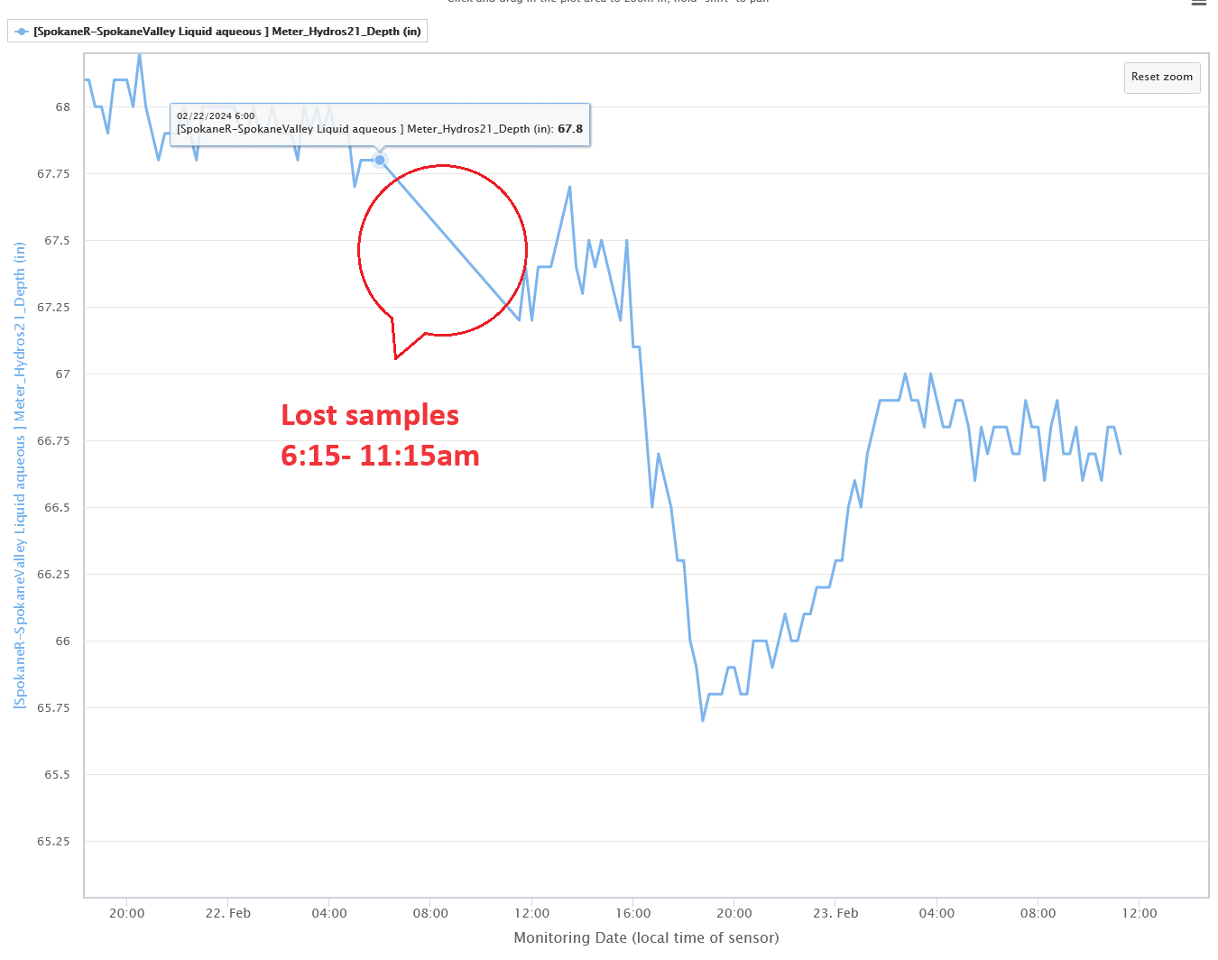
2024-02-23 at 11:53 AM #18340
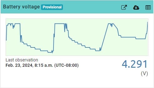
See attached, a picture is worth a 1000 words. This one has the 4400mAh battery. Installed the new micro sd card yesterday.
-
2024-02-23 at 2:43 PM #18342
Congrats – nice to see.
I guess the fundamental problem of power management is still there and can bite any time the power drops – and then likely will require a site visit to get the site restarted. Getting enough power is a band aid to enable reporting readings. So long as the power supplied exceeds the power used by a good margin it works. 🙂 I’ve found the real fix is in software using higher voltage thresholds – but it causes tradeoff
Its interesting the shape of the 2nd charging pulse – indicates lost data. Stepping to the larger graph, its more visible.
So the next layer of reliability issues, with the fix being in software. I predicted the problem in 2018, and had a solution for it in 2020 that I’m using,
Orderly data delivery – Queue messages for later sending,
So just advertising there is a fix for it 🙂
Attachments:
-
-
AuthorPosts
- You must be logged in to reply to this topic.