
Home › Forums › Mayfly Data Logger › XBee and Hologram LTE: issues connecting to internet
Tagged: LTE, Modem, monitor my watershed, Xbee
- This topic has 25 replies, 3 voices, and was last updated 2020-12-23 at 3:06 PM by
 James_NZ.
-
AuthorPosts
-
-
2020-07-20 at 1:26 PM #14352
I am unable to connect to the internet (and therefore monitor my watershed). After reading some other posts, it seems that I am not alone. However, I am still having problems even after reading some of the tips. Here are links to the forums that I have read:
- https://www.envirodiy.org/topic/xbee-r410m-cant-connect/
- https://www.envirodiy.org/topic/connecting-xbee3-lte-to-the-internet/
- https://www.envirodiy.org/topic/difficulty-connecting-to-mmw-with-lte-adapter/
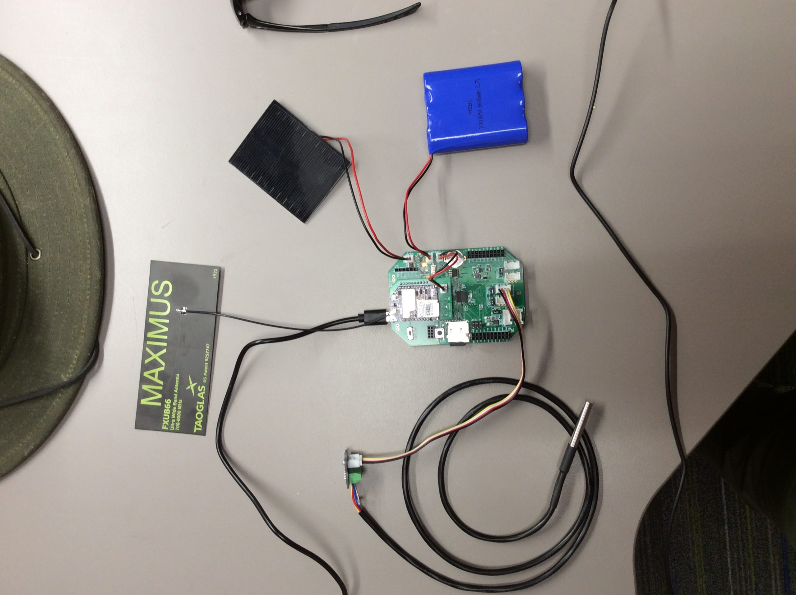
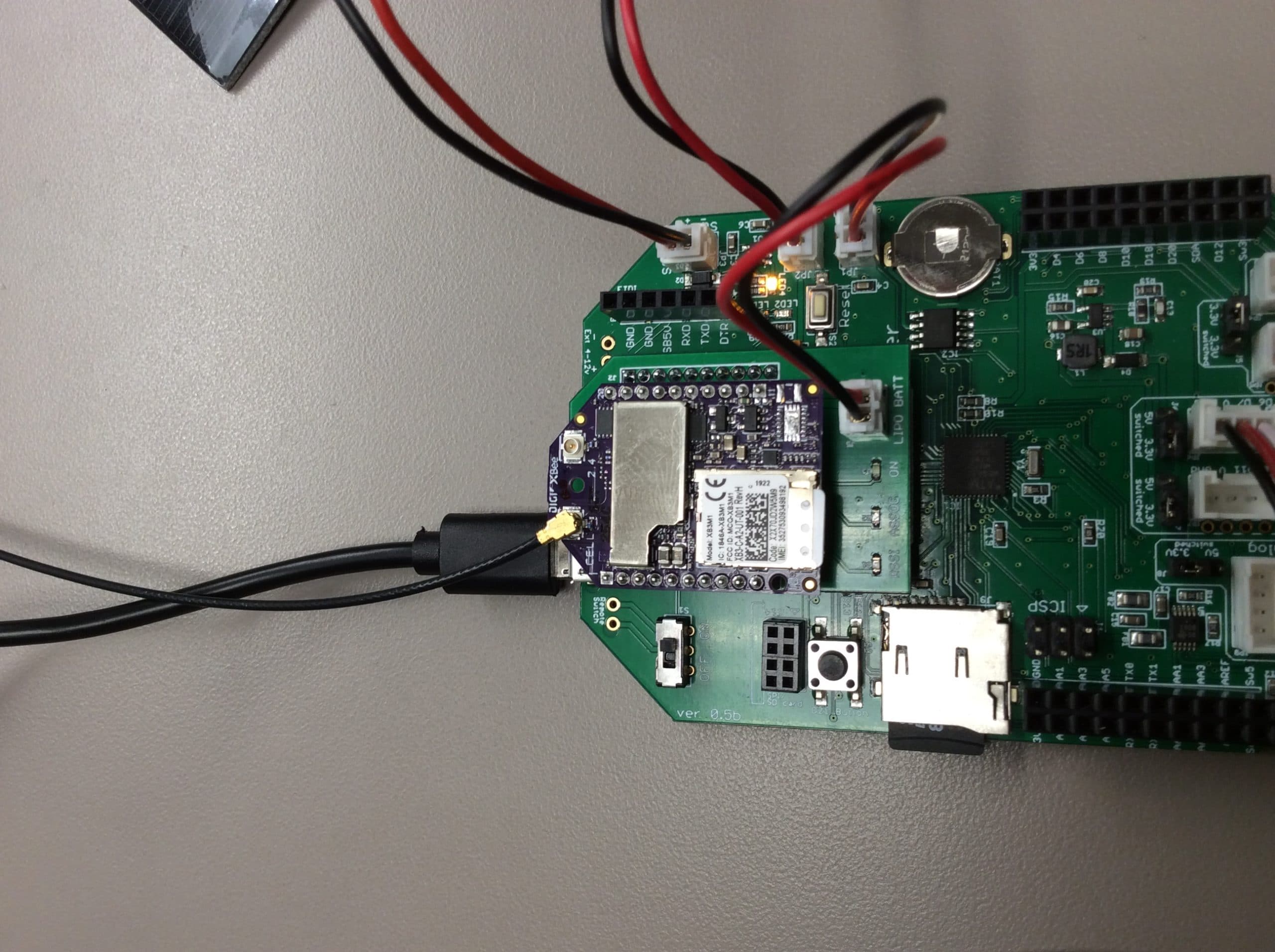
My unit hardware is (photos attached):
- Hologram SIM (the apn is set to “hologram”)
- LTE Bee Adapter
- Digi XBee 3 Cellular LTE-M/NB-IoT
- Tagolas Maximus FXUB66 Ultra Wide Antenna
My code is from the mmw example: https://github.com/EnviroDIY/ModularSensors/tree/master/examples/logging_to_MMW
Upon building the code to the Mayfly, it begins to set up the sensors and the RSSI light stays on for what seems like the full two minutes. It then turns off and the device alerts me that it “could not connect to internet for clock sync” and is “putting modem to sleep”.
I realize this is the same problem as posted in the second forum, linked to above. In that post, it is recommended to change the allowable connection time — “by changing the time in line 302 ‘if (modem.connectInternet(120000L))’.” I scanned the code in the mmw sketch and cannot find this command. Has the sketch been updated since that forum post?
Another tip, mentioned in the 3rd post linked above, was using “DigiXBeeLTEBypass”. I tried this and the result was the same.
Advice?
Attachments:
-
2020-07-20 at 3:47 PM #14356
Woops, yes, the example has changed since then. Sorry about that.
And, yes, you’re definitely not alone. I think issues with LTE connections are the top forum topic here. The LTE XBee3’s are so much trouble. I wish I could find something better.
From your pictures, your hardware connections look right. 🙂
As you’ve read, the first connection can take near forever. In the last update I simplified the clock sync, but that removed the control over how long to wait.
I put up a new program for you to try to see if you can get a connection: https://github.com/EnviroDIY/ModularSensors/blob/master/tools/LTExBee_FirstConnection/LTExBee_FirstConnection.ino It will set up the XBee, the carrier profile, the APN and then just sit and wait forever for a connection.
-
2020-07-22 at 12:14 PM #14359
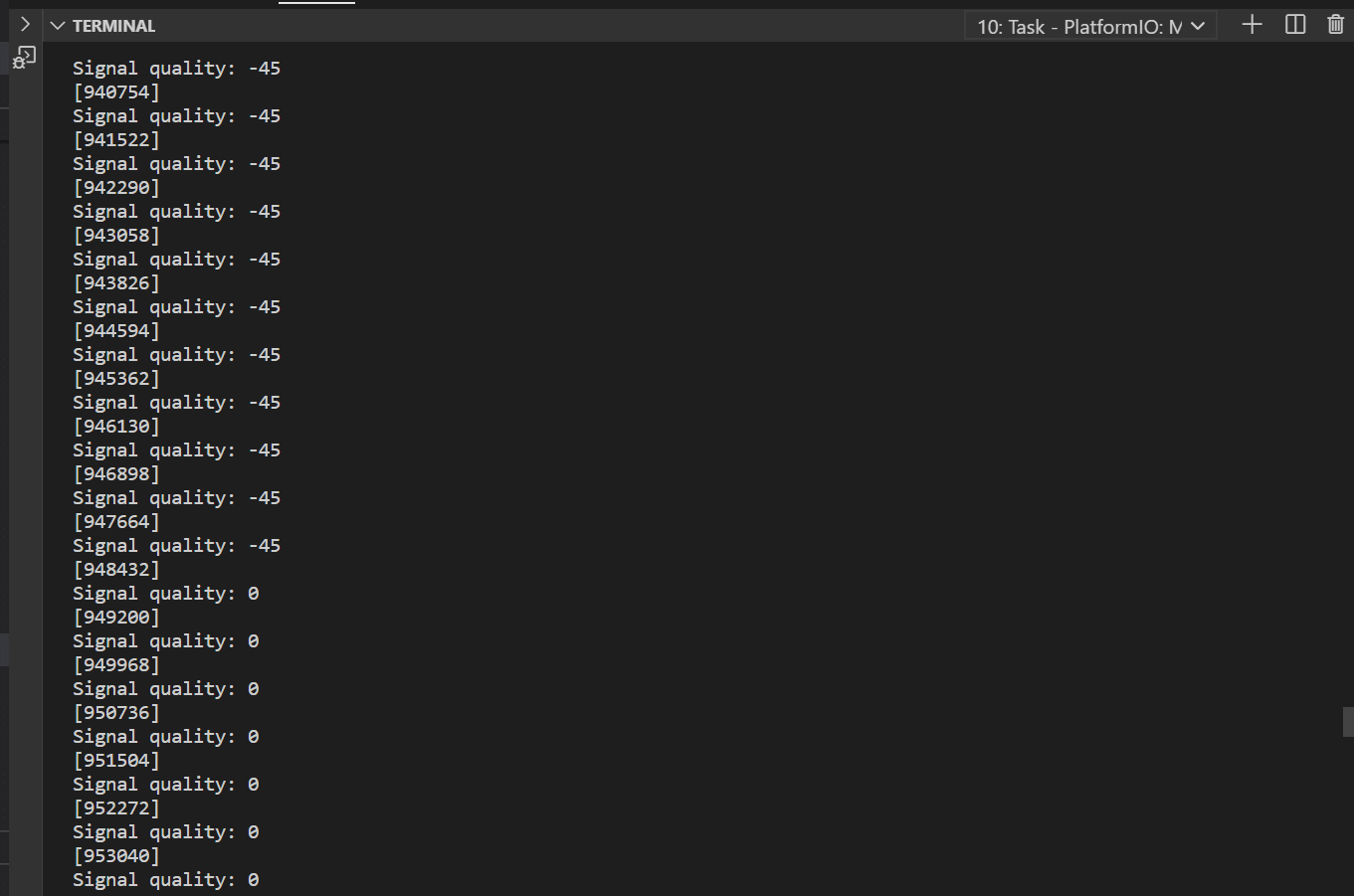
Thank you for taking the time to put that together! It worked… sort of. My SIM successfully connected to the internet! It took maybe 30 minutes. My signal quality is listed as -45.
After successfully connecting, I restart the Mayfly and build in the MMW example. This code fails to connect and I get the same result as before ( “could not connect to internet for clock sync” and is “putting modem to sleep”). I then re-try the code you provided above and it takes another 30 minutes or so to connect. And repeat.
Is there a way to do the ‘wait forever to connect’ strategy within the MMW example? Is this not an ideal solution?
P.S. I originally bought three of the Digi XBees. I have tried two of them, repeating all the steps above. They are acting the same.
-
2020-07-22 at 12:51 PM #14360
-45? The nominal RSSI range for the XBee3 is -113 dBm (really bad) to -51 dBm (excellent) so -45 either means your signal is *amazing* or not valid. I made a small change to that program to continuously print the quality so you can watch it to see if it changes while trying to register. When running that first connection sketch, are you seeing lots of
22or23responses (searching for the network) or are you getting25‘s (denied)? Can you copy the output from running for a minute or two and post it?Your pictures of your set-up look good. The battery’s not dead, right? Try (gently) wiggling the antenna to make sure its secure.
Are you sure there is AT&T signal available?
-
2020-07-22 at 2:35 PM #14361
The battery I am using is basically straight from the box so I was under the assumption that it was about 50% charged. I have not had the opportunity to complete the solder on the Voltaic solar panel. The antenna has been gently wiggled! I should also note that I did not remove the antenna when testing the second Digi XBee (to avoid unnecessary damage). So, I have gotten the same result with two different antenna, both with a seemingly secure connection. I am not certain that there AT&T is available but when it did connect, and came up on my Hologram account, I assumed there was. Also, I tried connecting to Verizon and had no luck connecting.
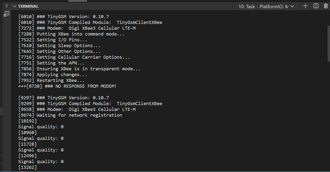
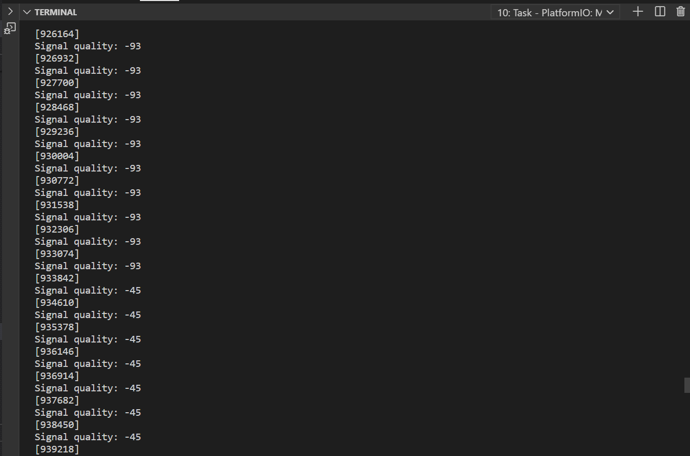
Attached are snapshots of the serial monitor as it moves through trying to connect. I cut it up because it was pretty long. I see no 22s, 23s or 25s. But I do see many zeros. These changed into -93 for a while and then to -45 and then back to zeros (as you can see in the pictures). Is this what you were looking for?
-
2020-07-22 at 2:44 PM #14366
Woops, sorry, the XBee uses carriage returns instead of new lines so the 22/23/25 isn’t appearing.
Add this to your platformio.ini:
INI123monitor_flags=--eolCRYour log will suddenly get a lot longer.
-
2020-07-22 at 2:57 PM #14367
But it seems like you might have kind-of low signal, if that -93 is valid. Does anyone around have an AT&T cellphone? Do they have ok signal?
Hologram doesn’t work on Verizon. Sometimes they say the do, and for a while we actually got it to work, but usually it’s only AT&T.
-
2020-07-22 at 3:03 PM #14368
You can try adding a network scan before the “waiting for network registration” section. It won’t help you connect, but it should show what networks have signal.
C++1234// Scan for networks - this is probably really slowgsmModem.sendAT(GF("AS"));gsmModem.waitResponse(180000L, GF("S"), GF("ERROR"));while (Serial1.available()) { Serial.println(Serial1.readStringUntil('\r')); } -
2020-07-22 at 3:18 PM #14370
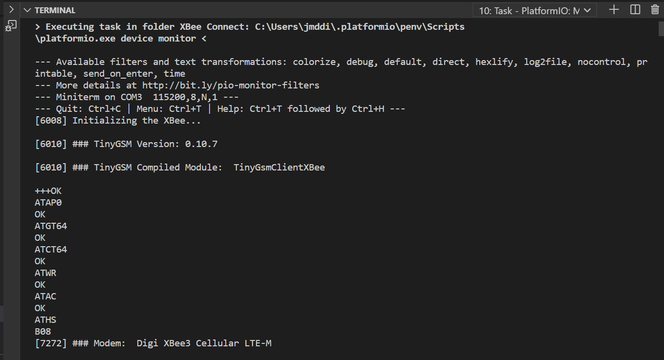
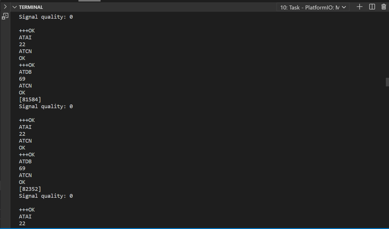
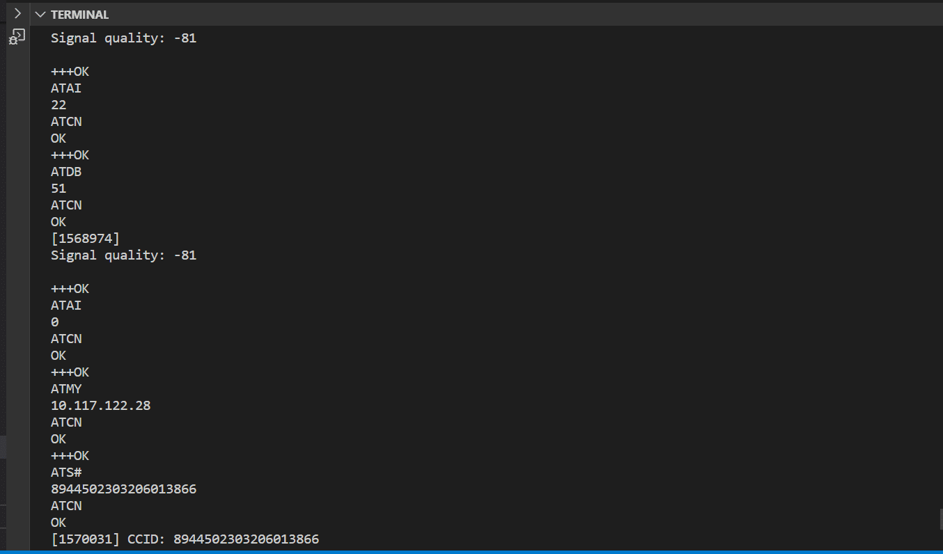
Got it! So this time I left it long enough to connect (or I think it is connecting). Attached are snips of the monitor. It repeats for quite a while and then right at the end it changes. So, pictures 3 & 4 are almost consecutive.
I commented back after fixing my ini file and did not reload the page and didn’t see your other comments! I will try the network scan tomorrow!
-
2020-07-22 at 3:37 PM #14375
Wahoo, that’s connected! *Usually* after you’ve made a few connections it connects more quickly the next time, but signal quality of -81 isn’t stellar, so it might still be somewhat slow. Are you testing at where you’re going to deploy? If so, you might want to take some time fiddling with just the right arrangement of the antenna and other wires to maximize your signal – you don’t want other wires to cross the antenna and I think you want a slight curve in the antenna’s cable. Small movements can make a surprising difference. If you’re planning to deploy somewhere else, and it’s easy to do so, you might want to run that “first connection” program again at your deployment location to see how long the connection takes. Hopefully it will be faster. Concrete office walls do a pretty good job of blocking cellular signals.
-
2020-07-27 at 1:11 PM #14386
Wanted to send an update: the XBee is now connecting to the internet in a timely manner! I saved the testing code for my future units. Thanks again!
-
2020-12-22 at 3:51 PM #14958
Hi,
I have a similar issue with our Xbee3 LTE. I have the hardware set up identical to how Letsid has it above. I am using the ‘LTExBee_FirstConnection.ino’ code, with the only amendment being a change of the apn to ‘m2m’ (as required for the Spark network). The serial output I get from this code (after the initial setup) is: “Signal quality = 0”, over and over. I left this for an hour and still got the same message.
I have a few questions/comments that might get me a step closer:
1) Do I need to do anything to the sim before inserting it? Cellphone sims need to be activated, but the instructions from the NZ IOT provider (Spark) suggested that I should just insert it, turn on the LTE and then ‘test’ it from their developers portal.
2) Cell signal is unlikely to be the problem as I am testing this at my house in an urban area. However, is there a way I can query the LTE to see what signals it can see (rather than connected signal) to determine if the antenna is the problem?
3) Spark provides 3G, 4G, 5G and CAT-M1 coverage (Spark NZ network coverage). CAT-M1 seems to be the most appropriate for this method. Should I be doing something different to specify that I want to use the CAT-M1 network as opposed to the 3G or 4G?
4) I understand network bands need to align with the capability of the Xbee3 LTE. Spark CAT-M1 operates on Band 28 (700MHz) and Band 3 (1800MHz). The LTE seems to support bands 1, 2, 3, 4, 5, 8, 12, 13, 17, 18, 19, 20, 25, 26, 28 and 39, therefore I don’t think this is the problem.
5) Is there anything else that anyone can think of that might prevent the LTE from working here in New Zealand?
6) Would I have more success with a Hologram sim? These operate on the Vodafone network in NZ, but at least my methods would align with everyone else.
5) Another option would be to purchase a developers board and ensure that network connections are addressed in XCTU rather than operating blind on the Mayfly. Would this help?
As always, thanks for your help.
Regards,
James
-
2020-12-22 at 4:20 PM #14959
Just a further update on above. The IoT provider thinks that the UBlox needs to be told to register.
He suggested using the AT commands:
AT+CPIN?
AT+CREG?
AT+COPS=?Am I correct in assuming that the way to do this would be via the code below:
1234567891011121314151617gsmModem.sendAT(GF("CPIN?"));gsmModem.waitResponse(180000L, GF("S"), GF("ERROR"));while (Serial1.available()) {Serial.println(Serial1.readStringUntil('\r'));}gsmModem.sendAT(GF("CREG?"));gsmModem.waitResponse(180000L, GF("S"), GF("ERROR"));while (Serial1.available()) {Serial.println(Serial1.readStringUntil('\r'));}gsmModem.sendAT(GF("COPS=?"));gsmModem.waitResponse(180000L, GF("S"), GF("ERROR"));while (Serial1.available()) {Serial.println(Serial1.readStringUntil('\r'));} -
2020-12-22 at 4:23 PM #14960
- If the SIM provider says you don’t have to do anything to activate the SIM, I’d trust them.
- Yes, the “AS” command in the first run sketch does that. (line ~147)
- If you’re using an XBee3 LTE-M it *only* supports LTE-M and LTE NB-IoT. Since your provider doesn’t use NB-IoT, LTE-M will be the only possibility. That first-run program you’re using sets the bee to use LTE-M preferentially in line 121, which is what you want.
- This might be your issue. Yes, the module can use all of those bands, but you would commonly set it up to use a specific carrier profile that will optimize searching to only the bands that carrier uses. In the example sketch (line 115), the carrier profile is set to 2/AT&T. Most of AT&T’s traffic is on bands 2, 4, and 12 (https://www.phonearena.com/news/Cheat-sheet-which-4G-LTE-bands-do-AT-T-Verizon-T-Mobile-and-Sprint-use-in-the-USA_id77933). So if you’re setting your module to AT&T, it will not attempt to use band 3 or band 28. I think you would want to select “1” as your carrier profile here, which will set the module for “SIM ICCID/IMSI select.” *Hopefully* your SIM and the module will be friendly enough with each other that the module will then switch its mode to that for your SIM. This doesn’t always work, though. I know with a Hologram SIMs in the USA the module will attempt to switch to 100/Standard Europe based on the SIM ICCID, which won’t work. But with a T-Mobile SIM the “SIM ICCID/IMSI select” setting immediately correctly matched to the 5/T-Mobile profile and the connection worked right away. If just switching the carrier profile to 1 doesn’t work, there are commands to manually try and force the bands. Start with the profile, though.
- Well, I generally think getting the development board is a good idea if you want to ever do much with the XBee (like test multiple boards or update firmware) but it shouldn’t be strictly needed.
-
2020-12-22 at 4:34 PM #14961
No, I don’t think those command suggestions from your IoT provider will help much.
The
CPINcommand checks if your SIM is locked by a pin number. If your SIM provider didn’t mention it and give you the pin number, you shouldn’t need it.The proper equivalent to the
CREGcommand is already being used in the gsmModem.isNetworkConnected() command on line 155 of the first run sketch.The
COPS=?command is the same as theAScommand on line 147.You don’t see exactly those commands in the code because you’re not talking to the u-blox chip directly; you’re talking to a Digi programmed processor that’s talking to the u-blox chip. You can issue commands directly to the u-blox chip by switching your XBee3 from Digi recommended “transparent” mode to “bypass” mode. It might be necessary to do that to adjust the band scanning to exactly match your provider, but hopefully just setting the profile will work.
-
2020-12-22 at 4:52 PM #14963
Thanks for the prompt reply Sara. You must love these LTE’s by now!
I have had some feedback from Spark who suggest that they have lots of other SARA R410M devices running on the network.
Sara, does the information below mean anything to you? I figure that I would construct code using “gsmModem.sendAT(GF(“”)) ” to send these configurations to the LTE?
12345678910111213141516171819202122232425262728293031323334353637383940414243444546474849505152535455565758# Initial module SW resetat+cfun=15# Set verbose error codesat+cmee=2# model identificationat+cgmmSARA—R410-02B# Get the current module FW versionat+cgmrL0.0.00.00.05.06 [Feb 03 2018 13:00:41]# set MNO profile to look from SIM (ICCID)at+umnoprof=1# Force only LTE-M1 radio protocols# at+urat=7,7,7at+urat=7# set Spark LTE-M1 bands in bit-mask - LTE-M1 using Band-3 (1800MHz) & Band-28 (700MHz)at+ubandmask=0,134217732# configure APN & save configat+cgdcont=1,”IP”,”m2m”at&w# Second module SW resetat+cfun=15# enable NW registration and location registrationat+cereg=1# Check if NW registration has occurred and if we can see the Spark LTE-M1 NW broadcastsat+cops?+cops: 0,0,"Spark NZ Spark NZ",8OK# check if NW registered (result code should be ‘1,1’ - ‘enabled’, registered’at+cereg?+CEREG: 1,1OK# check if PDP context attached on APN1 (result code should be ‘1’)at+cgatt?+CGATT: 1OK# check on configured active APN’sat+cgdcont?+CGDCONT: 1,"IP","m2m","10.1.2.137",0,0,0,0OK# check on configured active APN’s acquired WAN IP address(s)at+cgpaddr=1+CGPADDR: 1,10.1.2.137OK -
2020-12-22 at 5:03 PM #14964
To use those commands exactly, you need to switch to bypass mode.
But, the proper equivalent of almost all of those commands area already being used anyway, so you don’t need to change much at all.
They are setting the profile to
1just like I suggested (that’s theUMNOPROF). Other than making that change, I think the only thing you need to add is setting the bands (at+ubandmask=0,134217732in their example). In the first-run sketch, right below setting the network technology (line 123), add the digi equivalent for setting the band mask:gsmModem.sendAT(GF(“BM134217732”));
gsmModem.waitResponse(); -
2020-12-22 at 5:08 PM #14965
Thanks so much for your help. I will try this tonight when I get home!
Have a wonderful Christmas.
James
-
2020-12-22 at 5:12 PM #14966
The settings for the profile and the band mask should be saved on the module, so you should only need to set it up one time. But, if you’re using ModularSensors, you’ll see that a bunch of the set-up from the first-run sketch is copied in the set-up for the modem in the example sketches. So when using those examples, you’ll either need to delete those extra set-up lines (and use what’s saved on the module) or change the profile to 1 and add the band mask every time. I’d lean toward re-setting it every time rather than hope the module remembered correctly.
Also, yes, I’ve spent enough time fiddling with the LTE and other modules that I knew exactly what all of those commands were right off the top of my head. The Digi command for setting bands was the only one I needed to check. These things are really troublesome.
-
2020-12-23 at 3:09 AM #14967
Sigh, so I thought we had this but I’m getting the same result. My code is below, as well as the serial output.
Any thoughts?
123456789101112131415161718192021222324252627282930313233343536373839404142434445464748495051525354555657585960616263646566676869707172737475767778798081828384858687888990919293949596979899100101102103104105106107108109110111112113114115116117118119120121122123124125126127128129130131132133134135136137138139140141142143144145146147148149150151152153154155156157158159160161162163164165166167168169170171172173174175176177178179180181182183184185186187188189190191192193194195196#define TINY_GSM_MODEM_XBEE#define TINY_GSM_RX_BUFFER 64#define TINY_GSM_YIELD_MS 2#define TINY_GSM_DEBUG Serial#include <Arduino.h>#include <StreamDebugger.h>#include <TinyGsmClient.h>StreamDebugger debugger(Serial1, Serial);TinyGsm gsmModem(debugger);const char* apn = "m2m";void setup() {// Set the reset pin HIGH to ensure the Bee does not continually resetpinMode(20, OUTPUT);digitalWrite(20, HIGH);// Set the sleep_rq pin LOW to wake the BeepinMode(23, OUTPUT);digitalWrite(23, LOW);// Set the input pin modepinMode(19, INPUT);// Set console baud rateSerial.begin(115200);delay(10);// Set XBee module baud rateSerial1.begin(9600);// Wait for warm-up, probably overkilldelay(6000);}void loop() {/** First run the TinyGSM init() function for the XBee. */DBG(F("Initializing the XBee..."));gsmModem.init();/** Then enter command mode to set pin outputs. */DBG(F("Putting XBee into command mode..."));if (gsmModem.commandMode()) {DBG(F("Setting I/O Pins..."));/** Enable pin sleep functionality on <code>DIO9</code>.* NOTE: Only the <code>DTR_N/SLEEP_RQ/DIO8</code> pin (9 on the bee socket) can be* used for this pin sleep/wake. */gsmModem.sendAT(GF("D8"), 1);gsmModem.waitResponse();/** Enable status indication on <code>DIO9</code> - it will be HIGH when the XBee* is awake.* NOTE: Only the <code>ON/SLEEP_N/DIO9</code> pin (13 on the bee socket) can be* used for direct status indication. */gsmModem.sendAT(GF("D9"), 1);gsmModem.waitResponse();/** Enable CTS on <code>DIO7</code> - it will be <code>LOW</code> when it is clear to send* data to the XBee. This can be used as proxy for status indication if* that pin is not readable.* NOTE: Only the <code>CTS_N/DIO7</code> pin (12 on the bee socket) can be used* for CTS. */gsmModem.sendAT(GF("D7"), 1);gsmModem.waitResponse();/** Enable association indication on <code>DIO5</code> - this is should be directly* attached to an LED if possible.* - Solid light indicates no connection* - Single blink indicates connection* - double blink indicates connection but failed TCP link on last* attempt** NOTE: Only the <code>Associate/DIO5</code> pin (15 on the bee socket) can be* used for this function. */gsmModem.sendAT(GF("D5"), 1);gsmModem.waitResponse();/** Enable RSSI PWM output on <code>DIO10</code> - this should be directly attached* to an LED if possible. A higher PWM duty cycle (and thus brighter* LED) indicates better signal quality.* NOTE: Only the <code>DIO10/PWM0</code> pin (6 on the bee socket) can be used for* this function. */gsmModem.sendAT(GF("P0"), 1);gsmModem.waitResponse();/** Enable pin sleep on the XBee. */DBG(F("Setting Sleep Options..."));gsmModem.sendAT(GF("SM"), 1);gsmModem.waitResponse();/** Disassociate from the network for the lowest power deep sleep. */gsmModem.sendAT(GF("SO"), 0);gsmModem.waitResponse();DBG(F("Setting Other Options..."));/** Disable remote manager, USB Direct, and LTE PSM* NOTE: LTE-M's PSM (Power Save Mode) sounds good, but there's no easy* way on the LTE-M Bee to wake the cell chip itself from PSM, so we'll* use the Digi pin sleep instead. */gsmModem.sendAT(GF("DO"), 0);gsmModem.waitResponse();/** Ask data to be "packetized" and sent out with every new line (0x0A)* character. */gsmModem.sendAT(GF("TD0A"));gsmModem.waitResponse();/* Make sure USB direct is NOT enabled on the XBee3 units. */gsmModem.sendAT(GF("P1"), 0);gsmModem.waitResponse();/** Set the socket timeout to 10s (this is default). */gsmModem.sendAT(GF("TM"), 64);gsmModem.waitResponse();DBG(F("Setting Cellular Carrier Options..."));// Carrier Profile - 0 = Automatic selection// - 1 = No profile/SIM ICCID selected// - 2 = AT&T// - 3 = Verizon// NOTE: To select T-Mobile, you must enter bypass mode!gsmModem.sendAT(GF("CP"), 1); //change to 1 for SparkgsmModem.waitResponse();// Cellular network technology - 0 = LTE-M with NB-IoT fallback// - 1 = NB-IoT with LTE-M fallback// - 2 = LTE-M only// - 3 = NB-IoT onlygsmModem.sendAT(GF("N#"), 0);gsmModem.waitResponse();//set the band mask for sparkDBG(F("Setting the Band Mask..."));gsmModem.sendAT(GF("BM134217732"));gsmModem.waitResponse();DBG(F("Setting the APN..."));/** Save the network connection parameters. */gsmModem.gprsConnect(apn);DBG(F("Ensuring XBee is in transparent mode..."));/* Make sure we're really in transparent mode. */gsmModem.sendAT(GF("AP0"));gsmModem.waitResponse();/** Write all changes to flash and apply them. */DBG(F("Applying changes..."));gsmModem.writeChanges();/** Finally, exit command mode. */gsmModem.exitCommand();/** Force restart the modem to make sure all settings take. */DBG(F("Restarting XBee..."));gsmModem.restart();} else {// wait a bitdelay(30000L);// try againreturn;}// Scan for networks - this is probably really slowgsmModem.sendAT(GF("AS"));gsmModem.waitResponse(180000L, GF("S"), GF("ERROR"));while (Serial1.available()) {Serial.println(Serial1.readStringUntil('\r'));}// Wait forever for a connectionDBG(F("Waiting for network registration"));while (!gsmModem.isNetworkConnected()) {int csq = gsmModem.getSignalQuality();DBG("Signal quality:", csq);delay(250);}// Scan for networks - this is probably really slowgsmModem.sendAT(GF("AS"));gsmModem.waitResponse(180000L, GF("S"), GF("ERROR"));while (Serial1.available()) {Serial.println(Serial1.readStringUntil('\r'));}// Print some stuff after connectedString ccid = gsmModem.getSimCCID();DBG("CCID:", ccid);String imei = gsmModem.getIMEI();DBG("IMEI:", imei);String imsi = gsmModem.getIMSI();DBG("IMSI:", imsi);String cop = gsmModem.getOperator();DBG("Operator:", cop);IPAddress local = gsmModem.localIP();DBG("Local IP:", local);// Shut downgsmModem.poweroff();DBG("Powering down.");// And do nothing forever more.while (1) {}}123456789101112131415161718192021222324252627[6008] Initializing the XBee...[6010] ### TinyGSM Version: 0.10.6[6010] ### TinyGSM Compiled Module: TinyGsmClientXBee[7272] ### Modem: Digi XBee3 Cellular LTE-M[7288] Putting XBee into command mode...[7522] Setting I/O Pins...[7610] Setting Sleep Options...[7645] Setting Other Options...[7716] Setting Cellular Carrier Options...[7751] Setting the Band Mask...[7778] Setting the APN...[7876] Ensuring XBee is in transparent mode...[7895] Applying changes...[7972] Restarting XBee...+++[8742] ### NO RESPONSE FROM MODEM![9320] ### TinyGSM Version: 0.10.6[9320] ### TinyGSM Compiled Module: TinyGsmClientXBee[9678] ### Modem: Digi XBee3 Cellular LTE-MATAS[189704] Waiting for network registration[190222] Signal quality: 0[190990] Signal quality: 0[191758] Signal quality: 0[192526] Signal quality: 0[193294] Signal quality: 0..... for two hours... -
2020-12-23 at 9:32 AM #14968
Ugh; I thought it would work. 🙁
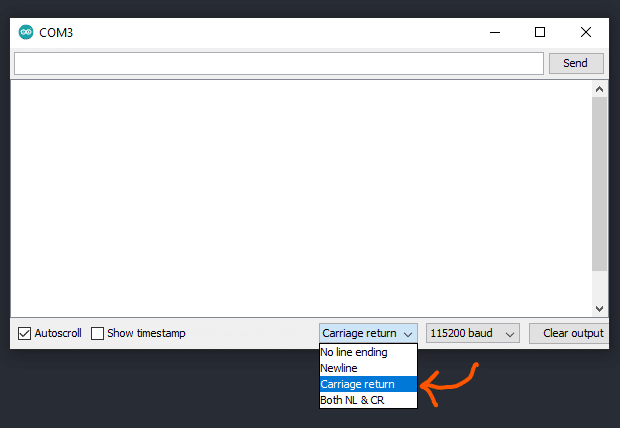
Two things to try. First, try running the same thing but change your serial monitor settings to show you more of the output. If you’re running the Arduino IDE, when you open the serial port monitor, use the drop-down at the bottom to select “Carriage return.” (See screenshot.) In PlatformIO, add this to the [mayfly] (or [env]) section of your platformio.ini:
INI123monitor_flags =--eolCRThen rerun the same program and you should see much more extensive output. It’s not going to fix anything, but it would be interesting to see the output.
Attachments:
-
2020-12-23 at 10:17 AM #14969
And a new program to try to set it up in bypass to see if we can see what’s failing that way. I’ve also posted this on GitHub here: https://github.com/EnviroDIY/ModularSensors/blob/master/tools/LTExBee_FirstConnectionBypass/LTExBee_FirstConnectionBypass.ino
Arduino123456789101112131415161718192021222324252627282930313233343536373839404142434445464748495051525354555657585960616263646566676869707172737475767778798081828384858687888990919293949596979899100101102103104105106107108109110111112113114115116117118119120121122123124125126127128129130131132133134135136137138139140141142143144145146147148149150151152153154155156157158159160161162163164165166167168169170171172173174175176177178179180181182183184185186187188189190191192193194195196197198199200201202203204205206207208209210211212213214215216217218219220221222223224225226227228229230231232233234235236#define TINY_GSM_MODEM_SARAR4#define TINY_GSM_RX_BUFFER 64#define TINY_GSM_YIELD_MS 2#define TINY_GSM_DEBUG Serial#include <Arduino.h>#include <StreamDebugger.h>#include <TinyGsmClient.h>StreamDebugger debugger(Serial1, Serial);TinyGsm gsmModem(debugger);const char* apn = "m2m";void setup() {// Set the reset pin HIGH to ensure the Bee does not continually resetpinMode(20, OUTPUT);digitalWrite(20, HIGH);// Set the sleep_rq pin LOW to wake the BeepinMode(23, OUTPUT);digitalWrite(23, LOW);// Set the input pin modepinMode(19, INPUT);// Set console baud rateSerial.begin(115200);delay(10);// Set XBee module baud rateSerial1.begin(9600);// Wait for warm-up, probably overkilldelay(6000);}void loop() {bool success = false;DBG(F("Putting XBee into command mode..."));for (uint8_t i = 0; i < 5; i++) {/** First, wait the required guard time before entering command mode. */delay(1010);/** Now, enter command mode to set all pin I/O functionality. */gsmModem.streamWrite(GF("+++"));success = gsmModem.waitResponse(2000, GF("OK\r")) == 1;if (success) break;}if (success) {DBG(F("Setting I/O Pins..."));/** Enable pin sleep functionality on <code>DIO9</code>.* NOTE: Only the <code>DTR_N/SLEEP_RQ/DIO8</code> pin (9 on the bee socket) can be* used for this pin sleep/wake. */gsmModem.sendAT(GF("D8"), 1);success &= gsmModem.waitResponse(GF("OK\r")) == 1;/** Enable status indication on <code>DIO9</code> - it will be HIGH when the XBee* is awake.* NOTE: Only the <code>ON/SLEEP_N/DIO9</code> pin (13 on the bee socket) can be* used for direct status indication. */gsmModem.sendAT(GF("D9"), 1);success &= gsmModem.waitResponse(GF("OK\r")) == 1;/** Enable CTS on <code>DIO7</code> - it will be <code>LOW</code> when it is clear to send* data to the XBee. This can be used as proxy for status indication if* that pin is not readable.* NOTE: Only the <code>CTS_N/DIO7</code> pin (12 on the bee socket) can be used* for CTS. */gsmModem.sendAT(GF("D7"), 1);success &= gsmModem.waitResponse(GF("OK\r")) == 1;/** Enable association indication on <code>DIO5</code> - this is should be directly* attached to an LED if possible.* - Solid light indicates no connection* - Single blink indicates connection* - double blink indicates connection but failed TCP link on last* attempt** NOTE: Only the <code>Associate/DIO5</code> pin (15 on the bee socket) can be* used for this function. */gsmModem.sendAT(GF("D5"), 1);success &= gsmModem.waitResponse(GF("OK\r")) == 1;/** Enable RSSI PWM output on <code>DIO10</code> - this should be directly attached* to an LED if possible. A higher PWM duty cycle (and thus brighter* LED) indicates better signal quality.* NOTE: Only the <code>DIO10/PWM0</code> pin (6 on the bee socket) can be used for* this function. */gsmModem.sendAT(GF("P0"), 1);success &= gsmModem.waitResponse(GF("OK\r")) == 1;/** Enable pin sleep on the XBee. */DBG(F("Setting Sleep Options..."));gsmModem.sendAT(GF("SM"), 1);success &= gsmModem.waitResponse(GF("OK\r")) == 1;DBG(F("Setting Other Options..."));/** Disable remote manager, USB Direct, and LTE PSM.* NOTE: LTE-M's PSM (Power Save Mode) sounds good, but there's no easy* way on the LTE-M Bee to wake the cell chip itself from PSM, so we'll* use the Digi pin sleep instead. */gsmModem.sendAT(GF("DO"), 0);success &= gsmModem.waitResponse(GF("OK\r")) == 1;/* Make sure USB direct is NOT enabled on the XBee3 units. */gsmModem.sendAT(GF("P1"), 0);success &= gsmModem.waitResponse(GF("OK\r")) == 1;// DBG(F("Setting Cellular Carrier Options..."));// // Carrier Profile - 1 = No profile/SIM ICCID selected// gsmModem.sendAT(GF("CP"),1);// success &= gsmModem.waitResponse(GF("OK\r")) == 1;// // Cellular network technology - LTE-M/NB IoT// gsmModem.sendAT(GF("N#"),0);// success &= gsmModem.waitResponse(GF("OK\r")) == 1;// Make sure airplane mode is off - bypass and airplane mode are// incompatible.DBG(F("Making sure airplane mode is off..."));gsmModem.sendAT(GF("AM"), 0);success &= gsmModem.waitResponse(GF("OK\r")) == 1;DBG(F("Turning on Bypass Mode..."));/** Enable bypass mode. */gsmModem.sendAT(GF("AP5"));success &= gsmModem.waitResponse(GF("OK\r")) == 1;/** Write changes to flash. */gsmModem.sendAT(GF("WR"));success &= gsmModem.waitResponse(GF("OK\r")) == 1;/** Apply changes. */gsmModem.sendAT(GF("AC"));success &= gsmModem.waitResponse(GF("OK\r")) == 1;// Finally, force a reset to actually enter bypass mode - this// effectively exits command mode.DBG(F("Resetting the module to reboot in bypass mode..."));gsmModem.sendAT(GF("FR"));success &= gsmModem.waitResponse(5000L, GF("OK\r")) == 1;// Allow 5s for the unit to reset.delay(500);// Re-initialize the TinyGSM SARA R4 instance.DBG(F("Attempting to reconnect to the u-blox SARA R410M module..."));success &= gsmModem.init();gsmModem.getModemName();} else {// wait a bitdelay(30000L);// try againreturn;}DBG(F("Setting Cellular Carrier Options..."));// Turn off the cellular radio while making network changesgsmModem.sendAT(GF("+CFUN=0"));gsmModem.waitResponse();// Mobile Network Operator Profile// - 0: SW default// - 1: SIM ICCID selected// - 2: ATT// - 3: Verizon// - 4: Telstra// - 5: T-Mobile US// - 6: China Telecom// - 8: Sprint// - 19: Vodafone// - 20: NTT DoCoMo// - 21: Telus// - 28: SoftBank// - 31: Deutsche Telekom// - 32: US Cellular// - 33: VIVO// - 39: SKT// - 44: Claro Brasil// - 45: TIM Brasil// - 46: Orange France// - 90: global// - 100: Standard Europe// - 101: Standard Europe No-ePCO (The factory-programmed configuration of// this profile is the same of the standard Europe profile (<MNO>=100), but// the ePCO is disabled.)// - 102: Standard Japan (global)// - 198: AT&T 2-4-12 (The factory programmed configuration of this profile// is the same of the AT&T profile (<MNO>=2), but the LTE band 5 is// disabled.)// - 201: GCF-PTCRB (This profile is meant only for conformance testing.)gsmModem.sendAT(GF("+UMNOPROF="), 1);gsmModem.waitResponse();// Selected network technology - 7: LTE Cat.M1// - 8: LTE Cat.NB1// Fallback network technology - 7: LTE Cat.M1// - 8: LTE Cat.NB1// NOTE: As of 2020 in the USA, AT&T and Verizon only use LTE-M// T-Mobile uses NB-IOTgsmModem.sendAT(GF("+URAT="), 7, ',', 8);gsmModem.waitResponse();// Set the band mask manually if needed// bit 0 = band 1; bit 127 = band 128gsmModem.sendAT(GF("+UBANDMASK="), 0, ',', 134217732);gsmModem.waitResponse();// Restart the module to apply changes and bring back to full functionalitygsmModem.restart();// Check again for the carrier profile (to ensure it took)// If 1/SIM select was used, this will show what the SIM pickedgsmModem.sendAT(GF("+UMNOPROF?"));gsmModem.waitResponse();// Scan for networks - this is probably really slowDBG(F("Scanning for networks. This may take up to 3 minutes"));gsmModem.sendAT(GF("+COPS=0"));gsmModem.waitResponse();gsmModem.sendAT(GF("+COPS=?"));gsmModem.waitResponse(180000L);// Wait forever for a connectionDBG(F("Waiting for network registration"));while (!gsmModem.isNetworkConnected()) {int csq = gsmModem.getSignalQuality();DBG("Signal quality:", csq);delay(250);}// Print some stuff after connectedString ccid = gsmModem.getSimCCID();DBG("CCID:", ccid);String imei = gsmModem.getIMEI();DBG("IMEI:", imei);String imsi = gsmModem.getIMSI();DBG("IMSI:", imsi);String cop = gsmModem.getOperator();DBG("Operator:", cop);IPAddress local = gsmModem.localIP();DBG("Local IP:", local);// Shut downgsmModem.poweroff();DBG("Powering down.");// And do nothing forever more.while (1) {}}You should set your end of line back to newline instead of carriage return when running this or you might get a lot of extra blank lines in the printout.
-
2020-12-23 at 10:19 AM #14970
I wish there was some magical way to know why the connection isn’t working or to bribe the thing into working. Obviously from this forum, and from dozens of issues in the TinyGSM library, a lot of people have trouble figuring out the right settings to get their board to connect.
-
2020-12-23 at 2:09 PM #14973
Hi Sara,
Here’s the output from the carriage return code extension:
123456789101112131415161718192021222324252627282930313233343536373839404142434445464748495051525354555657585960616263646566676869707172737475767778798081828384858687888990919293949596979899100101102103104105106107108109110111112113114115116117118119120121122123124125126127128129130131132133134135136137138139140141142143144145146147148149150151152153154155156157158159160161162163164165166167168169170171172173174175[6008] Initializing the XBee...[6010] ### TinyGSM Version: 0.10.6[6010] ### TinyGSM Compiled Module: TinyGsmClientXBee+++OKATAP0OKATGT64OKATCT64OKATWROKATACOKATHSB08[7272] ### Modem: Digi XBee3 Cellular LTE-MATCNOK[7288] Putting XBee into command mode...+++OK[7522] Setting I/O Pins...ATD81OKATD91OKATD71OKATD51OKATP01OK[7610] Setting Sleep Options...ATSM1OKATSO0OK[7645] Setting Other Options...ATDO0OKATTD0AOKATP10OKATTM64OK[7716] Setting Cellular Carrier Options...ATCP1OKATN#0OK[7751] Setting the Band Mask...ATBM134217732OK[7778] Setting the APN...ATANm2mOKATAM0OKATWROKATACOK[7876] Ensuring XBee is in transparent mode...ATAP0OK[7895] Applying changes...ATWROKATACOKATCNOK[7972] Restarting XBee...+++OKATAM1OKATWROKATACOKATFROK+++[8742] ### NO RESPONSE FROM MODEM!+++OKATAM0OKATWROKATACOKATCNOK[9320] ### TinyGSM Version: 0.10.6[9320] ### TinyGSM Compiled Module: TinyGsmClientXBee+++OKATAP0OKATGT64OKATCT64OKATWROKATACOKATHSB08[9678] ### Modem: Digi XBee3 Cellular LTE-MATCNOKATAS[189704] ### NO RESPONSE FROM MODEM![189704] Waiting for network registration+++OKATAI22ATCNOK+++OKATDB69ATCNOK[190222] Signal quality: 0+++OKATAI22ATCNOK+++OKATDB69ATCNOK[190990] Signal quality: 0+++OKATAI22ATCNOK+++OKATDB69ATCNOK[191758] Signal quality: 0.... and so on ... -
2020-12-23 at 2:29 PM #14974
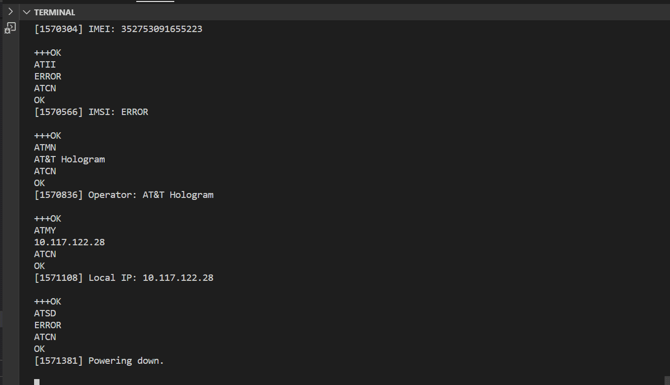
And here’s the bypass output. I think this worked! Any idea why, and how I could transfer to my modular sensors code?
James
123456789101112131415161718192021222324252627282930313233343536373839404142434445464748495051525354555657585960616263646566676869707172737475767778798081828384858687888990919293949596979899100101102103104105106107108109110111112113114115116117118119120121122123124125126127128129130131132133134135136137138139140141142143144145146147148149150151152153154155156157158159160161162163164165166[6008] Putting XBee into command mode...[7133] Setting I/O Pins...ATD81ATD91ATD71ATD51ATP01[7227] Setting Sleep Options...ATSM1[7245] Setting Other Options...ATDO0ATP10[7284] Making sure airplane mode is off...ATAM0[7303] Turning on Bypass Mode...ATAP5ATWRATAC[7385] Resetting the module to reboot in bypass mode...ATFR[7903] Attempting to reconnect to the u-blox SARA R410M module...[7905] ### TinyGSM Version: 0.10.6[7907] ### TinyGSM Compiled Module: TinyGsmClientSaraR4ATATATAT␀ATATATATATATATATATATATOKATE0OKAT+CMEE=2OKAT+CGMIu-bloxOKAT+GMMSARA-R410M-02BOK[12443] ### Modem: u-blox SARA-R410M-02B[12443] ### Modem: u-blox SARA-R410M-02BAT+CTZU=1OKAT+CPIN?+CPIN: READYOKAT+CGMIu-bloxOKAT+GMMSARA-R410M-02BOK[12701] ### Modem: u-blox SARA-R410M-02B[12703] Setting Cellular Carrier Options...AT+CFUN=0OKAT+UMNOPROF=1OKAT+URAT=7,8OKAT+UBANDMASK=0,134217732OKATOKAT+CFUN=15OK[16013] ### TinyGSM Version: 0.10.6[16013] ### TinyGSM Compiled Module: TinyGsmClientSaraR4AT␀␀ATATATATOKATE0+CPIN: READYOKAT+UMNOPROF?+UMNOPROF: 0OK[17674] Scanning for networks. This may take up to 3 minutesAT+COPS=0OKAT+COPS=?+COPS: (1,"530 05","530 05","53005",8),(1,"530 01","530 01","53001",8),(1,"530 01","530 01","53001",9),,(,23)(12K[197736] ### Unhandled: +COPS: (1,"530 05","530 05","53005",8),(1,"530 01","530 01","53001",8),(1,"530 01","530 01","53001",9),,(,23)(12K[197742] Waiting for network registrationAT+CEREG?+CEREG: 0,1OKAT+CCID+CCID: 8964050087214794989OK[197879] CCID: 8964050087214794989AT+CGSN356726104223995OK[197937] IMEI: 356726104223995AT+CIMI530058721479498OK[197996] IMSI: 530058721479498AT+COPS?+COPS: 0,0,"Spark NZ Spark NZ",8OK[198080] Operator: Spark NZ Spark NZAT+CGPADDR=1+CGPADDR: 1,100.103.173.237OK[198158] Local IP: 100.103.173.237AT+CPWROFFOK[198199] Powering down. -
2020-12-23 at 3:06 PM #14975
Further update. My modular sensors code is logging to MMW flawlessly. I never thought I would see the day! Obviously something worked with Sara’s bypass code:
The only other thing I would like to know is how to code the settings into a standard modular sensors code so that my LTE doesn’t forget them.
Thanks again Sara!
James (& the rest of the UoW team)
-
-
AuthorPosts

- You must be logged in to reply to this topic.