
@fisherba
Active 2 years, 4 months agoForum Replies Created
-
AuthorPosts
-
Noted. Thank you. This is in my next couple weeks of existence.
The CTD does not allow an internal calibration, but we do a calibration in the lab with conductivity standards and apply the calibrated data as a calculated variable.
This is maybe semantics, but the Mayfly wouldn’t be a source of quality (or the lack thereof). That’s the sensor’s job. CTDs are usually pretty durable.
Here’s a video of the process of installing the driver:
https://mediaspace.minnstate.edu/media/Mayfly+driver+in+Arduino+IDE/1_py60bdus
Nope. The instructions here: https://www.envirodiy.org/mayfly/software/ say to not use 2.0. I don’t use the Arduino IDE for anything but getting people started. But the tutorial I sent will lead you to this Mayfly driver and through a whole set of steps that will get you up and running. It may look TLDR, but I think it will help.
If the usb port doesn’t exist, then the most probable cause is that the driver is not installed or not valid/current.
Mine looks something like this:
The Mayfly doesn’t have a bluetooth radio built in, so that port is not actually the one that is connected to a Mayfly. The bluetooth port is everpresent on Macs because you have bluetooth on your computer, but the Mayfly would require an extra radio to be able to connect by bluetooth. This is not the correct port to view what’s happening on the Mayfly. The correct port will have “usb” somewhere in the string.
Did Blink successfully upload? The mayfly can only handle one sketch at a time. The fact that your board is flashing in the ways you describe means that it is probably not fried.
As far as I can detect, you have not yet connected to your board. The serial monitor would be a way to connect to any board and see what’s on it. There are lots of charging cables that do not convey data, so that could be an issue. Now that you have learned about the serial port, try a few different cables again to see if that’s the issue.
You also need to have the Mayfly driver. In the Arduino IDE under Tools>Boards Manager, you need to confirm that the Mayfly is selected. (https://www.envirodiy.org/mayfly/software/)
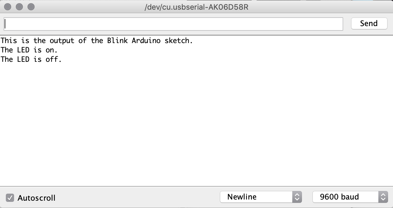
If the existing sketch is from the EnviroDIY Modular Sensors code wrapper, the serial baud should be 115200. In the arduino IDE, connected with usb, mayfly power on, if you press the little magnifying lens at the top right corner of the window for any sketch, that will open the serial monitor. You should be prompted to manually select the port (something with USB if you are on a mac) and baudrate (115200, maybe).
The bluetooth port is not your mayfly.
I did this tutorial that could get you acquainted with the serial monitor: https://envirodiy.github.io/LearnEnviroDIY/01-ArduinoBasics/index.html
What’s uploaded on your Mayfly will determine the baud rate for the serial monitor. It looks like you haven’t uploaded anything yet, but there’s an existing sketch on the board. It’s getting power and charging (per the lights you see). The baud rate is probably slower than 57600.
-
AuthorPosts