
 Welcome to EnviroDIY, a community for do-it-yourself environmental science and monitoring. EnviroDIY is part of
 Home › Forums › Environmental Sensors › Couldn’t find DTS-12 turbidity sensor address
- This topic has 6 replies, 2 voices, and was last updated 2026-09-16 at 2:13 PM by
Sabin.

-
AuthorPosts
-
-
2026-09-08 at 6:40 PM #19901
I am trying to connect DTS-12 with mayfly data logger.
With this instruction https://www.envirodiy.org/topic/logging-mayfly-with-decagon-sdi-12-sensor/, I am using Grove – Screw Terminal to connect the sensor. Red is connected to vcc,black to gnd and white(the data) to D2. The screw terminal is then connected to D 4-7.
When I start the program to change the address, the wiper of this sensor runs. This needs around 12V of power. So, the mayfly is doing this. But the code output is “No sensor detected. Check physical connections.”. This is the code that I am using https://github.com/EnviroDIY/Arduino-SDI-12/blob/master/examples/b_address_change/b_address_change.ino -
2026-09-09 at 5:24 PM #19902
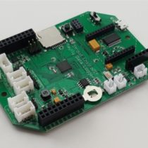
What is the board version of the Mayfly data logger board that you’re using? Did you set the jumper header next to the Grove jack to the 12v jumper setting? Are you using the latest version of the EnviroDIY_SDI12 library?
-
2026-09-09 at 5:53 PM #19903
I am using Mayfly v1.1. The turbidity sensor is connected with Screw Terminal.
I downloaded the zip from EnviroDIY_SDI12 using https://github.com/EnviroDIY/Arduino-SDI-12/archive/master.zip.
I am able to run the wiper with these:123Serial.println("Sending 0M2!");mySDI12.sendCommand("0M2!");delay(1000);Using this inside loop that runs every 30 seconds push the wiper. But, sending command to get data results in nothing.
while (mySDI12.available()) { Serial.write(mySDI12.read()); } This mySDI12.read() return nothing. I checked and see that all the wires are connected properly.
How do I do this? “set the jumper header next to the Grove jack to the 12v jumper setting? “. If my wiper which needs 12V is running well, doesn’t that mean it’s on 12V setting?-
2026-09-10 at 10:59 AM #19904
There are instructions on the Grove jack jumper settings on this page, including a photo showing examples of what the jumper position would look like for the different options: https://www.envirodiy.org/mayfly/hardware/jumper-settings/
-
-
2026-09-10 at 1:43 PM #19905
The page says 12V is the default and my sensor is getting 12V because I could send command to run wiper which needs 12V and it works. But data measurement command doesn’t work.
-
2026-09-10 at 3:03 PM #19906
I’m not sure what you mean by “The page says 12V is the default” because the default Grove jack jumper setting of the Mayfly v1.1 boards has always been 3.3v. You have to manually move a jumper if you want to select 5v or 12v for the Grove jacks on the Mayfly v1.1 board. So verify that the jumper next to the Grove jack you’re using for the sensor is set to 12v. It would also be good to use a voltmeter (also known as a multimeter) to measure the voltage you’re applying to the sensor to verify that the voltage is really 12v and isn’t sagging during the motor movement or sensor sampling. It could be that the motor is drawing more current than the Mayfly can supply. The user manual for the DTS-12 says it can draw up to 200mA during wiping, which is right around the upper limit of what the Mayfly v1.1 can supply at 12v. So if you watch the output voltage of the Mayfly with a voltmeter during the wiping action, you should be able to see if it stays near 12v or if it drops. The sensor manual also mentions that the SDI12 sampling commands are different depending on which firmware the sensor has, so you might want to check with the manufacturer to find out what version your sensor is operating with. Have you successfully used that sensor with other dataloggers besides Mayfly boards? You could also try powering the sensor directly from an external 12v battery and only using the data (and ground) lines from the Mayfly to handle the communication. (be sure to connect the ground of the Mayfly board to the ground of the external battery so they’re both using the same ground reference). Then verify that you’re sending the proper sample and measurement report commands according to the tables in the user manual appendix.
-
-
2026-09-16 at 2:13 PM #19913
I will check with the power level. My assumption was that I could send SDI 12 commands and wiper runs, therefore Mayfly was able to provide those voltage.
I have tried the sensor with three other mayfly logger and among two SDI-12 D4-7, only one of each logger is able to make this wiper run.
One thing is I tried running mayfly with “?!” command but it get no response. I know the command is working because when i do “aM!” where a is the address (in my case 1M!) which means wipe and measure, the wipe happens but the command doesn’t give back any ack nor does it give response after waiting for while for the measured data.
Last week, i changed address to 1 and somehow it worked for a while but now it’s not working.
-
-
AuthorPosts

- You must be logged in to reply to this topic.