
Home › Forums › Mayfly Data Logger › Logging Mayfly with Decagon SDI-12 Sensor
- This topic has 21 replies, 6 voices, and was last updated 2021-06-11 at 9:13 AM by
Selbig.
-
AuthorPosts
-
-
2017-04-03 at 5:03 PM #2129
Several people have asked about how to get a Decagon CTD or other SDI-12 sensor logging with the Mayfly, so I’m trying to put together a list of steps to help everyone out. Our convention at here at the Stroud Center is to plug all SDI-12 sensors into the D6-7 jack (J6) with pin 7 as our SDI-12 data pin. These instructions are written to follow that.
The first step is to decide how you’re going to connect the sensor to your Mayfly. The easiest way is to make use of the white Grove jacks on the bottom of the Mayfly board. Here are some ways to adapt your sensor to the Grove jacks without using a soldering iron.
For a bare wire sensor: (ie, Decagon 5TM)
— Buy a $2.90 Grove 4-port screw terminal adapter: https://www.seeedstudio.com/Grove-Screw-Terminal-p-996.html and some Grove cables: https://www.seeedstudio.com/Grove-Universal-4-Pin-Buckled-20cm-Cable-%285-PCs-pack%29-p-936.html
— Connect your sensor’s ground wire to ground on the screw terminal adapter. If you are holding the screw terminal adapter with the green screw terminal on the top and the white grove jack on the bottom, the ground pin is all the way on the right.
— Connect your sensor’s power wire to Vcc. This is next to the ground.
— Connect your sensor’s data wire to D2, which is next to Vcc. [This is Stroud convention, D1 can also be used.]
— If your sensor has a braided shield wire, either cut it or connect it with ground.
— Use the Grove cable to connect the screw terminal adapter to the D6-7 Jack (J6).For a sensor with a stereo cable: (ie, Decagon CTD or Decagon ES2)
— Buy a 3.5mm stereo female TRS jack to terminal adapter, such as this one: https://smile.amazon.com/Cerrxian-Terminal-Headphone-Converter-Adapter/dp/B06W2KB8ZV and a 4 pin male jumper to Grove cable: https://www.seeedstudio.com/Grove-4-pin-Male-Jumper-to-Grove-4-pin-Conversion-Cable-%285-PCs-per-Pack%29-p-1565.html
— Put the black wire from the Grove conversion cable into the ground on the jack-to-terminal adapter. The jumpers can be inserted and tightened into the screw terminal just like wires.
— Put the red wire into the “R” (ring/right) slot on the terminal.
— Put the white wire into the “T” (tip) or “L” (left) slot on the terminal. (Which letter appears on the terminal might depend on the brand.)
— Fold and secure the white yellow wire out of the way.
— Plug the Grove cable into the D6-7 Jack (J6). -
2017-04-03 at 5:08 PM #2130
Up to 61 SDI-12 sensors can be connected to the same pin of the Mayfly. It is more stable to use the same pin for all the SDI-12 sensors you wish to connect rather than using different pins for each because this allows you to create only one instance of the SDI-12 object in your code. To connect multiple sensors to that pin, you can use a Grove branch cable (https://www.seeedstudio.com/Grove-Branch-Cable-%285PCs-pack%29-p-847.html) or a Grove hub (https://www.seeedstudio.com/Grove-I2C-Hub-p-851.html).
-
2017-04-03 at 6:14 PM #2133
Another option for connecting a sensor’s 3.5mm stereo headphone plug is to use these stereo jacks:
https://www.amazon.com/uxcell-Stereo-Female-Adapter-Connector/dp/B013D1U90S
Just strip the black, red, and white wires of a Grove cable and solder them to the corresponding terminals of the jack.And the easiest way to do it is to use our custom Grove-to-3.5mmStereoJack adapter board:
http://envirodiy.org/wp-content/uploads/grove_stereo.jpg
We hope to have these in our Amazon store later in April.-
2017-04-03 at 11:19 PM #2138
Yup, doing the soldering will make your 3.5mm jack connection much prettier and more secure than using the screw terminals. If you’re skilled with a soldering iron, it’s the way to go.
If you’re skill-less and solder-less like I am, the jacks with screw terminals are a solution.
-
-
2017-04-03 at 6:43 PM #2134
Once you have physically connected your sensor to your Mayfly board, the next step is to download the library to communicate with the it from GitHub. If you are only interested in the SDI-12 library, download it here: https://github.com/EnviroDIY/Arduino-SDI-12/archive/master.zip. If you would like to download a collection of libraries that might be useful in communicating with and logging data from sensors, including the SDI-12 library, download this: https://github.com/EnviroDIY/Libraries/raw/master/libraries.zip.
To install the libraries into the Arduino IDE, follow the instructions for Manual Installation on the Arduino library guide: https://www.arduino.cc/en/guide/libraries. If you are using PlatformIO you can install only the SDI-12 library using the terminal prompt command: platformio lib -g install “Arduino-SDI-12” or the entire collection of libraries using the command: pio lib -g install https://github.com/EnviroDIY/Libraries.git#platformio. For another IDE, follow the installation instructions for that IDE.
If you have not yet downloaded any IDE or program to communicate with your Mayfly, I highly recommend PlatformIO over the IDE created by Arduino.cc
-
2017-04-03 at 10:50 PM #2135
The next step is to set the SDI-12 address of the sensor. Communication with the sensor depends on its 1-character alphanumeric address (1-9, A-Z, a-z). Unfortunately, Decagon ships all of its sensors programmed to an SDI-12 address of 0, which cannot be used to get measurements from the sensor.
Within the SDI-12 library on GitHub, there is an example with instructions for changing the address. Find it here: https://github.com/EnviroDIY/Arduino-SDI-12/tree/master/examples/b_address_change
-
2017-04-03 at 11:03 PM #2136
Now that your sensor is connected and has an address set, you can get data from it using code like this:
C++1234567891011121314151617181920212223242526272829303132333435363738394041424344454647484950515253545556575859606162636465666768697071SDI12 mySDI12(_dataPin);mySDI12.begin();delay(500); // allow things to settlemyCommand = "";myCommand += _SDI12address;myCommand += "M!"; // SDI-12 measurement myCommand format [address]['M'][!]mySDI12.sendCommand(myCommand);Serial.println(myCommand); // For debuggingdelay(30);// wait for acknowlegement with format [address][ttt (3 char, seconds)][number of measurments available, 0-9]sdiResponse = "";while (mySDI12.available()) // build response string{char c = mySDI12.read();if ((c != '\n') && (c != '\r')){sdiResponse += c;delay(5);}}mySDI12.flush();// find out how long we have to wait (in seconds).unsigned int wait = 0;wait = sdiResponse.substring(1,4).toInt();Serial.print(F("Waiting ")); // For debuggingSerial.print(wait); // For debuggingSerial.println(F(" seconds for measurement")); // For debugging// Set up the number of results to expectnumMeasurements = sdiResponse.substring(4,5).toInt();Serial.print(numMeasurements); // For debuggingSerial.println(F(" results expected")); // For debuggingunsigned long timerStart = millis();while((millis() - timerStart) < (1000 * wait)){if(mySDI12.available()) // sensor can interrupt us to let us know it is done early{Serial.println("Wait interrupted!"); // For debuggingmySDI12.flush();break;}}delay(30);mySDI12.flush();Serial.println(F("Requesting data")); // For debuggingmyCommand = "";myCommand += _SDI12address;myCommand += "D0!"; // SDI-12 command to get data [address][D][dataOption][!]mySDI12.sendCommand(myCommand);Serial.println(myCommand); // For debuggingdelay(30);Serial.println(F("Receiving data")); // For debuggingmySDI12.read(); // ignore the repeated SDI12 addressfloat sensorValues[numMeasurements] = {0}; // Create an array to receive datafor (int i = 0; i < numMeasurements; i++){float result = mySDI12.parseFloat();sensorValues[i] += result;Serial.print(F("Result #")); // For debuggingSerial.print(i); // For debuggingSerial.print(F(": ")); // For debuggingSerial.println(result); // For debugging}// Wait for and discard anything elsemySDI12.flush();Once you have an array of values from the sensor, you can save them to an SD card or anything you’d like.
-
2017-04-03 at 11:13 PM #2137
If you would prefer, you can also look into the Modular Sensors library, which has functions already built into it for getting data from a Decagon CTD, a Decagon ES2, and a Decagon 5TM and then logging that data to a SD card.
If you downloaded the full package of libraries I mentioned in #2134, the Modular Sensors library is already included in it. If not, you download the zip at https://github.com/EnviroDIY/ModularSensors/archive/master.zip and unzip that for the Arduino IDE or install in PlatformIO using “pio lib -g install https://github.com/EnviroDIY/ModularSensors.git”.
-
2017-04-03 at 11:24 PM #2139
One more thing: If you’re going to use your Mayfly as a logger, make sure you set the real time clock first! I’ve written a sketch and tiny executable to synchronize the Mayfly with your computer clock. You can find it here: https://github.com/EnviroDIY/Sodaq_DS3231/tree/master/examples/PCsync
-
2020-08-18 at 11:15 AM #14480
Hi Sara,
I am having issues when I come to this step and can use a little help troubleshooting my issue. I cannot get my sensor to connect to an address. I have an SDI-12 sensor with bare wires connected to grove 4-pin terminal adapter set up just as you explained in the instructions. All of the connections seem secure, but when I run the b_address_change sketch, it continuously runs through every slot saying “vacant” and gives the message “No sensor connected. Check physical connection.”
I am not sure what the issue could be and was wondering if you may have any ideas.
Thanks,
Steve
-
2020-08-18 at 12:57 PM #14484
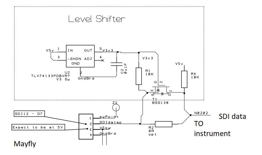
Just an FYI, as I understand the SDI-12 spec, the receiving instrument should receive 3.5V for a ‘0’ or space. The mayfly port is only capable of supplying 3.3V – so it may work for most SDI-12 instruments, and is working for one SDI-12 instrument I’m using
Typically with off-spec issues, things can work on some instruments and then not on others. So hopefully the problem is something simple, but just sharing my analysis.
Attachments:
-
2020-08-18 at 4:13 PM #14491
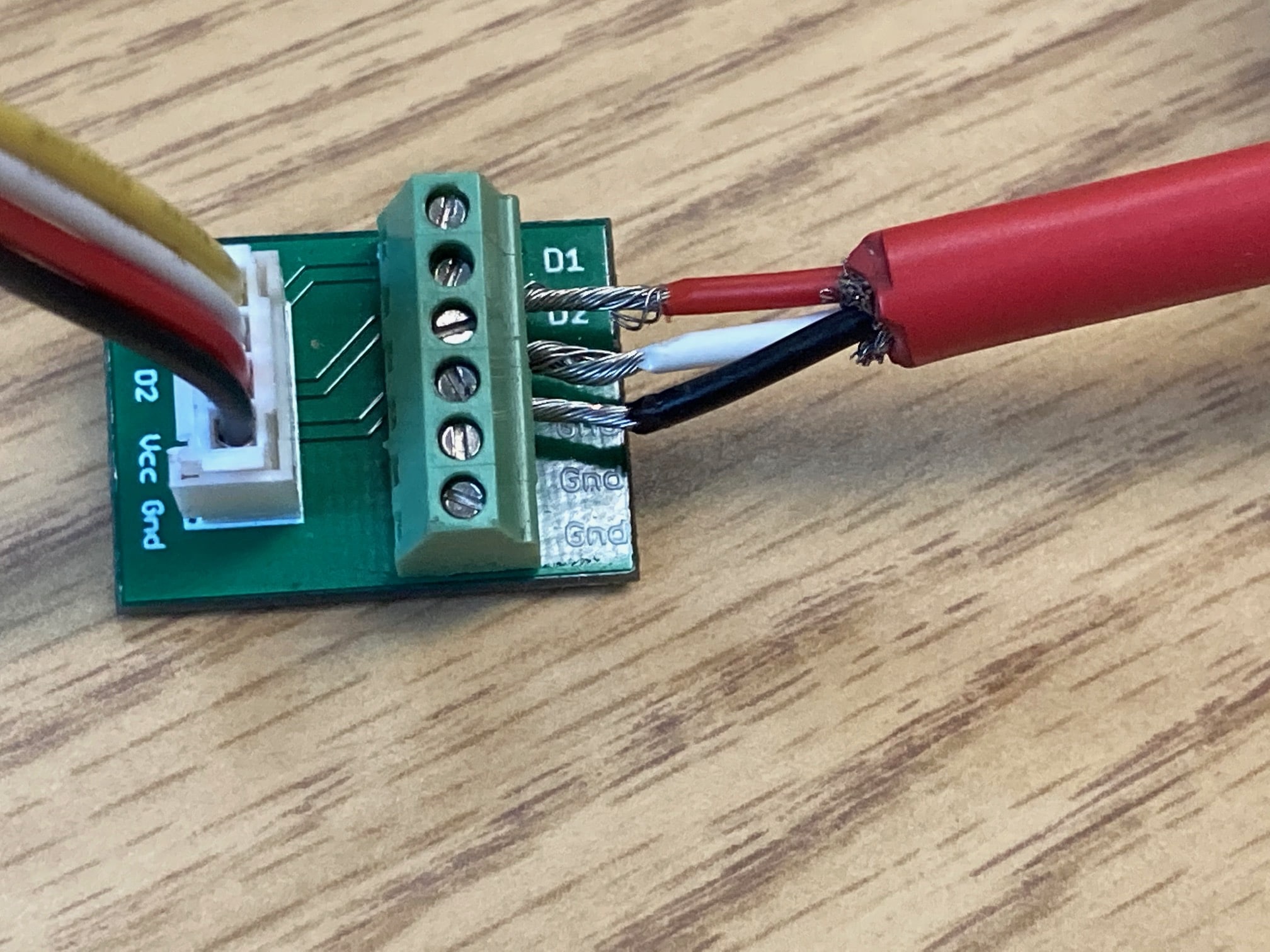
Check your wiring, the Meter group CTD sensor has a red wire for the data (signal) wire, white is positive voltage, and black is ground. It’s kind of backwards from most common DC sensor wires where red is usually the voltage supply wire. I’ve confirmed with the folks at Meter that the sensor works just fine at 3.3v.
-
2020-08-18 at 5:07 PM #14492
Our wiring looks to be correct. We talked with the folks at Meter and they had us test the voltage across the board which seemed fine. They are sending us an independent tester to see if it is an issue with the sensor itself.
-
2020-08-19 at 10:37 AM #14498
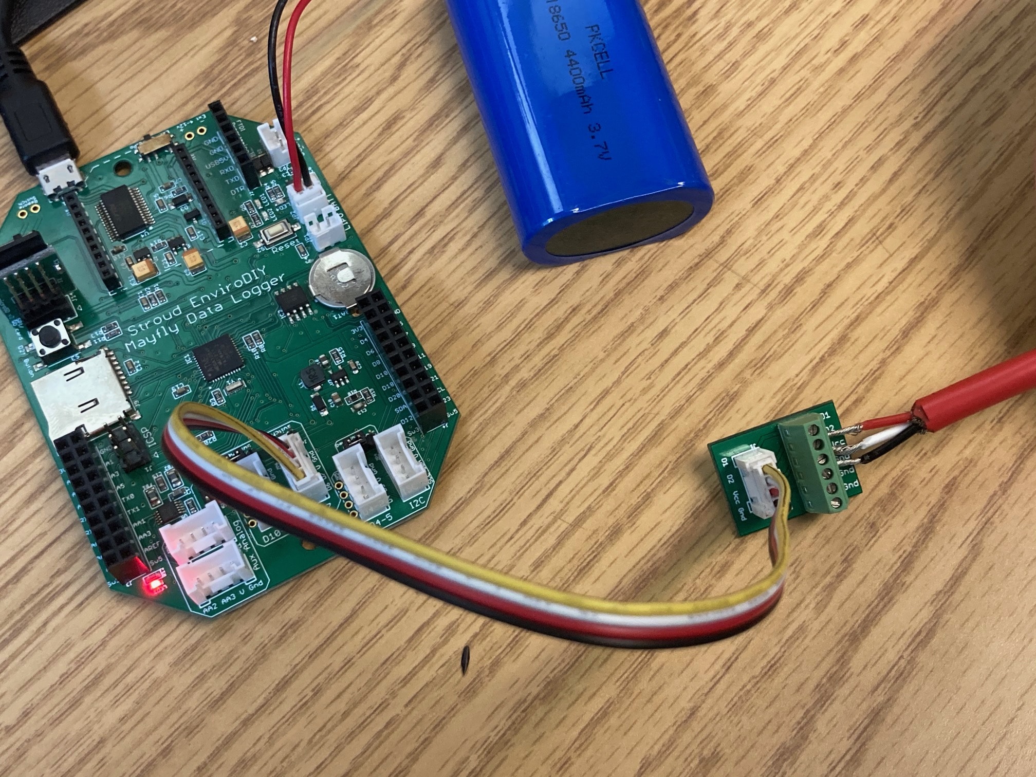
Can you post a picture of your sensor wiring showing how it’s connected to the terminal board and also a photo showing how it’s connected to the Mayfly? Did you make any changes at all to the address changing sketch? I’ve personally used almost 500 sensors (CTD, soil moisture, conductivity, etc) from Meter group and have never had a bad one right out of the box, so I have a feeling that the problem is likely in the wiring or the board configuration.
-
2020-08-19 at 12:33 PM #14503
Sure, no problem. I didn’t make any changes to the change address sketch. The Here is what I am looking at:
Attachments:
-
2020-08-19 at 12:42 PM #14506
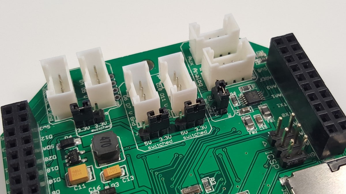
Thanks for the photo. The screw terminal pic looks fine, on pic of the Mayfly, it’s hard to see the jumper pins for the D6-D7 grove jack, but can you verify that there is a jumper (shunt) on the pins as seen in this photo.
Attachments:
-
2020-08-19 at 1:49 PM #14510
It looks like they are all there. Here is a better photo from a different angle.
Attachments:
-
-
-
2020-08-18 at 1:01 PM #14488
I have come up with an inline plug-in circuit that will do the voltage shifting ( and generate a +12V power and ESD protection) that I’m working on, so just mentioning it here. If anybody is interested in the discussion we could take it to a separate thread.
Attachments:
-
2020-08-25 at 12:58 PM #14532
scornia,
I was having the same problem with the address change sketch (using the Atom PlatforIO) so I tried using Arduino IDE and that worked. It saw the SDI-12 address of 0 at pin 7 and I successfully changed it to 1 and now I’m getting values from the Meter CTD-10. Good luck. Let me know if you have any questions.
-
2021-06-10 at 3:28 PM #15606
I am able to retrieve values from my Decagon ES2 sensor, but only temperature. Conductivity comes back with a value of 0.0. When I hook it up to a Campbell Scientific CR1000 logger, both conductivity and temperature come back with reasonable values. In fact, temperature is the same using the CR1000 as it is the Mayfly. I’m using the pre-programmed code for the Decagon from modular-sensors (see below). Any idea why the second location in the SDI array is returning but not the first?
123456789101112131415161718192021222324252627// ==========================================================================// Decagon ES2 Conductivity and Temperature Sensor// ==========================================================================#include <sensors/DecagonES2.h>const char* ES2SDI12address = "1"; // The SDI-12 Address of the ES2const int8_t ES2Power = sensorPowerPin; // Power pin (-1 if unconnected)const int8_t ES2Data = 7; // The SDI12 data pinconst uint8_t ES2NumberReadings = 5;// Create a Decagon ES2 sensor objectDecagonES2 es2(*ES2SDI12address, ES2Power, ES2Data, ES2NumberReadings);// ==========================================================================// Creating the Variable Array[s] and Filling with Variable Objects// ==========================================================================/** Start [variable_arrays] */Variable* variableList[] = {new ProcessorStats_SampleNumber(&mcuBoard),new ProcessorStats_FreeRam(&mcuBoard),new ProcessorStats_Battery(&mcuBoard),new MaximDS3231_Temp(&ds3231),new InSituRDO_DOpct(&insituRDO, "12345678-abcd-1234-ef00-1234567890aa"),new InSituRDO_DOmgL(&insituRDO, "12345678-abcd-1234-ef00-1234567890ae"),new InSituRDO_Temp(&insituRDO,"12345678-abcd-1234-ef00-1234567890ac"),new InSituRDO_Pressure(&insituRDO, "12345678-abcd-1234-ef00-1234567890ad"),new DecagonES2_Cond(&es2),new DecagonES2_Temp(&es2)-
2021-06-10 at 10:35 PM #15607
I’d need to see the rest of your sketch to make sure everything else is set up correctly for reading the sensor properly. Can you post your entire sketch, and tell me what version of the Modular Sensors library you’re using, and when you downloaded the other recommended supporting libraries like the EnviroDIY_SDI12 library?
-
-
2021-06-11 at 9:13 AM #15609
I was able to get it to work correctly. The only thing I changed was removal of the UUIDs for all of the variable pointers. I also moved the voltage pin so D7 was getting 5v instead of 3.3. I don’t know if that was what caused the initial error but it’s working now.
-
-
AuthorPosts


- You must be logged in to reply to this topic.