@ckillen
Active 1 year, 11 months agoForum Replies Created
-
AuthorPosts
-
Thanks all for your replies and help. I didn’t know about the MTU and limiting my message buffer under 1500 will easily solve that problem. I’ve put recovery code in my sketch to gracefully power down and reset the modem if it ever gets into a non-responsive state. I’ll be installing several units (Mayfly 1.1 and Sim7080) this summer. Thanks again.
I’ve had 2 problems with the SIM7080G modem on the Mayfly 1.x board. I wonder if anybody else has had the same problems or has any information that would help me.
My code is uses the TinyGsm library, and some parts of the ModularSensors code but is otherwise custom code. The code has been working in the field with Mayfly 0.5 and Digi LTEbee’s for years. I’m just starting to migrate the code to accept the Mayfly 1.1 and SIM7080 for new installations.
<u>Problem 1 – Posting too much data</u>: I found that doing an HTTP POST to my website fails when sending data greater than ~1400 bytes. The post is not accepted by Apache on my website. It works fine if sending less than 1400 bytes. The same code running on my Mayfly 0.5 with Digi LTEBee sends 6000 bytes with no problem. Can this be a timing thing? Is there some limit on the Sim7080?
<u>Problem2 – Modem Unresponsive</u>: After doing some tests, sending some AT commands, trying some new ideas online – the modem became unresponsive to any AT commands. This wasn’t a sleep/wake problem as it would sleep and wake as normal using pin 23 pulse. It took me a long time using parts of TinyGSM’s Factory Reset code and my test tool to get the modem to work again. Has anybody else run into this problem or has an idea what I did wrong? I’m worried that the module might get into this mode when it’s in the field.
Thanks for the reply Neil. The only reason I picked this thread to post was it started with a title “library can’t be found”. That’s been one of my problems. Let me know if there is a better place to post.
I’ve fixed my problems – mostly downlevel code in my library.
Trouble Compiling
We have several installations of Mayfly .5 & Digi modems in the field running code we developed years ago on the Arduino IDE. This winter we want to convert our solution to run on our Mayfly 1.0 & SIM7080, so I started by downloading the DRWI_SIM7080LTE sketch + several libraries – and of course I can’t get it to compile. Question – where is a list (or better yet a repository) of all the libraries + version that will compile? PS: I’d like to keep using the Arduino IDE, and not have to move over to Platform I/O, if that’s possible.
Shannon – thanks for your thoughtful reply. I’m sure I’ll be able to find the problem now. Answering your questions:
- I’m not switching D22 on.
- Humidity is a possibility. I’ll look for corrosion and add desiccant .
- I’ve had ants at another location but not this one…yet.
- I’ll make some tests as you suggest to isolate the problem. It might be easiest to just replace the Mayfly/modem as this station is far from my home. Then I can test the original equipment at home.
I do have a Digi modem and adapter card at all my locations. I plan to, but won’t be able to convert to new Mayfly and LTE BEE for another year as it will require substantial desk work – a winter job.
My stations as described above have been working fine for 3 years in the field. I’ve had a few components fail (12-5v buck converter, XBee daughter card, resistor divider) but otherwise very stable.
However, one Mayfly (0.5b) seems to be performing fine with 2 exceptions:
- the red LED3 is either solid ON or dim
- the ADC that records the 12v battery voltage across a resistor divider is a bit flaky
Is this a problem? I can’t understand from the logic diagrams what would turn on/off red LED3.
After struggling with power problems for years and buying several brands of 12v batteries and also using multiple batteries in parallel, I discovered I was looking in the wrong area. The solution for me was to find where power was being used and replacing inefficient modules with efficient ones. And the problems I found were surprising and probably NOT what you would expect. You really have to measure the current drain on all your devices to see where the problem lies – and it’s NOT going to be the Mayfly. In my case, the problems were:
- The 12v to 5v converter. Don’t believe the advertisements – measure it. I found cheap small buck converters are the best, but they vary widely.
- The solar panel charging circuit (if you have an external module) or the solar panel itself (if the charging circuit is built in). There should be very little current drain when the sun is not shining. BTW – bad charging circuits can kill a good battery too.
- A defective 10 year old SDI-12 sensor that was still working but using more and more power.
After fixing these problems, my stations need very little sun to keep the single 12v battery charged. I can even run my stations with no sun for months. Of course you should be putting the Mayfly, Modem and other devices to sleep between activities. Good luck.
Ps. you don’t need a LiPo battery on the Mayfly if you are powering it from the USB 5v. The LiPo’s cause problems too.
Cal
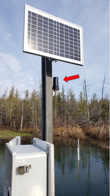
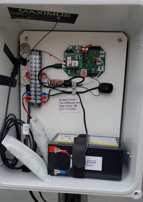
We just had an experience with antennae that might interest others. We have a dozen sensor stations in the field measuring water level of lakes in north western Michigan. Each station has an SDI-12 water level sensor connected to a Mayfly with a Digi XBee3 Cellular LTE-M/NB-IoT modem using a $3.00 antenna from Adafruit (https://www.adafruit.com/product/antenna) in a fiberglass enclosure. The system wakes up every 15 minutes to record water levels. At the top of each hour it connects to the tower and sends the collected measurements to our website; Lake-Man.com.
The last station that we installed was in a remote area with very poor LTE coverage. Our modem took minutes to connect and sometimes failed for several hours. Mobile phones have trouble connecting there. Moving the antenna around, shifting the battery position and trying different modems and options had little effect. After reading various posts on EnviroDIY, we decided to try other antennae mentioned there.
For us, the Maximus antenna and other internal-to-enclosure antennae performed similarly – that is to say poorly at this site. As a last resort, we installed a $16 external antenna from Amazon https://www.amazon.com/antenna using an SMB to UFL adapter cable.
The result was a major success – the modem connects within 10 seconds and hasn’t missed a transmission since we installed it. The 10 foot cable did not overly attenuate the signal in our experience.
Attachments:
All my devices came back online after 3:30 am ET – outage was around 15 hours by Hologram. I’m going to look at alternate providers if this happens again.
I know Hologram is having trouble. None of my devices could connect for past 7 hours.
-
AuthorPosts