
Home › Forums › Mayfly Data Logger › Trouble initializing XBee3 LTE-M
- This topic has 39 replies, 6 voices, and was last updated 2020-03-04 at 10:43 AM by
 Sara Damiano.
-
AuthorPosts
-
-
2018-10-25 at 5:14 PM #12612
I recently successfully set up a MayFly with GPRSbee radio. It works great.
I’m trying to get a second MayFly working with the Digi XBee3 LTE-M radio. This is on hologram, using a brand-new SIM card, which I understand should be possible. I’m not sure if I’m getting to that point, since even initializing the radio doesn’t seem to work 100%. I understand there is no soldering needed with this radio, and there is no JST connector as there is on the GPRSbee, so I’m not sure if there is a power issue… Anyway, with
#define MODEM_DEBUGGING_SERIAL_OUTPUT Serial
#define TINY_GSM_DEBUG Serialenabled, I’m getting output like this:
123456789101112131415161718192021222324252627282930313233343536373839404142434445464748Creating a new on/off method for the Digi XBee with power on pin -1 status on pin 19 and on/off by holding pin 23 low.Creating a new TinyGSM modem and client for the Digi XBee...Initializing Digi XBee...[1722] +++[1722] ### ..: OK , ERROR , , ,[1828] <<< OK[1837] ### AT: AP0[1839] ### ..: OK , ERROR , , ,[1843] <<< OK[1849] ### AT: WR[1851] ### ..: OK , ERROR , , ,[1882] <<< OK[1888] ### AT: AC[1890] ### ..: OK , ERROR , , ,[1894] <<< OK[1902] ### AT: GT64[1904] ### ..: OK , ERROR , , ,[1908] <<< OK[1914] ### AT: WR[1916] ### ..: OK , ERROR , , ,[1947] <<< OK[1953] ### AT: AC[1955] ### ..: OK , ERROR , , ,[1959] <<< OK[1966] ### AT: HS[1970] <<< B08[1978] ### AT: CN[1978] ### ..: OK , ERROR , , ,[1982] <<< OK[2109] +++[2111] ### ..: OK , ERROR , , ,[2217] <<< OK[2226] ### AT: SM 1[2228] ### ..: OK , ERROR , , ,[2232] <<< OK[2240] ### AT: SO 1[2240] ### ..: OK , ERROR , , ,[2246] <<< ERROR[2254] ### AT: WR[2254] ### ..: OK , ERROR , , ,[2285] <<< OK[2293] ### AT: AC[2293] ### ..: OK , ERROR , , ,[2297] <<< OK[2306] ### AT: CN[2306] ### ..: OK , ERROR , , ,[2310] <<< OK... Complete!So far, so good. Then, when trying to sync with NIST, I get:
123456789101112131415161718192021222324252627282930313233343536373839404142434445464748495051525354555657585960616263646566676869707172737475767778798081828384858687888990919293949596979899100101102103104105106107108109110111112113114115116117118119Attempting to synchronize RTC with NISTThis may take up to two minutes!Waiting up to 5 seconds for modem to respond to AT commands...[8724] +++[8724] ### ..: OK , ERROR , , ,[8830] <<< OK[8837] ### AT:[8837] ### ..: OK , ERROR , , ,[8841] <<< OKWaiting up to 120 seconds for cellular network...[8970] +++[8970] ### ..: OK , ERROR , , ,[8978] <<< OK[8984] ### AT: AI[8986] <<< FF[8994] ### AT: CN[8994] ### ..: OK , ERROR , , ,[8998] <<< OK[9125] +++[9127] ### ..: OK , ERROR , , ,[9234] <<< OK[9242] ### AT: AI[9244] <<< FF[9250] ### AT: CN[9252] ### ..: OK , ERROR , , ,[9256] <<< OK[9383] +++[9383] ### ..: OK , ERROR , , ,[9490] <<< OK[9498] ### AT: AI[9500] <<< FF[9508] ### AT: CN[9508] ### ..: OK , ERROR , , ,[9512] <<< OK[9639] +++[9641] ### ..: OK , ERROR , , ,[9748] <<< OK[9754] ### AT: AI[9758] <<< FF[9764] ### AT: CN[9766] ### ..: OK , ERROR , , ,[9771] <<< OK[9897] +++[9897] ### ..: OK , ERROR , , ,[10004] <<< OK[10012] ### AT: AI[10014] <<< FF[10022] ### AT: CN[10022] ### ..: OK , ERROR , , ,[10027] <<< OK[10153] +++[10156] ### ..: OK , ERROR , , ,[10262] <<< OK[10268] ### AT: AI[10272] <<< FF[10278] ### AT: CN[10280] ### ..: OK , ERROR , , ,[10285] <<< OK[10412] +++[10414] ### ..: OK , ERROR , , ,[10520] <<< OK[10526] ### AT: AI[10528] <<< FF[10536] ### AT: CN[10539] ### ..: OK , ERROR , , ,[10543] <<< OK[10670] +++[10670] ### ..: OK , ERROR , , ,[10776] <<< OK[10784] ### AT: AI[10786] <<< FF[10795] ### AT: CN[10795] ### ..: OK , ERROR , , ,[10799] <<< OK[10926] +++[10928] ### ..: OK , ERROR , , ,[11034] <<< OK[11042] ### AT: AI[11044] <<< FF[11051] ### AT: CN[11053] ### ..: OK , ERROR , , ,[11057] <<< OK[11184] +++[11186] ### ..: OK , ERROR , , ,[11292] <<< OK[11298] ### AT: AI[11302] <<< FF[11309] ### AT: CN[11311] ### ..: OK , ERROR , , ,[11315] <<< OK[11442] +++[11442] ### ..: OK , ERROR , , ,[11550] <<< OK[11556] ### AT: AI[11558] <<< FF[11567] ### AT: CN[11569] ### ..: OK , ERROR , , ,[11573] <<< OK[11700] +++[11700] ### ..: OK , ERROR , , ,[11806] <<< OK[11814] ### AT: AI[11816] <<< FF[11825] ### AT: CN[11825] ### ..: OK , ERROR , , ,[11829] <<< OK[11956] +++[11958] ### ..: OK , ERROR , , ,[12064] <<< OK[12070] ### AT: AI[12075] <<< FF[12081] ### AT: CN[12083] ### ..: OK , ERROR , , ,[12087] <<< OK[12214] +++[12216] ### ..: OK , ERROR , , ,[12468] ### NO RESPONSE!And then lots and lots of NO RESPONSE! lines until the 120 seconds is up. Am I missing something major here? Thanks.
-
2018-10-25 at 7:09 PM #12613
OK, looking at the GitHub issue, it looks like I may need to Solder SJ13 after all…?
-
2018-10-26 at 12:33 PM #12615
The Mayfly’s bee footprint was originally set up to only power modules that require moderate current supplied to the Vcc pin of the module, such as Xbee RF modules (900Mhz and 2.4Ghz), Bee wifi, and Bee bluetooth. There are even GPS modules with the Bee footprint that work great on the Mayfly. Then when we started using 2G and 3G cellular modules from SODAQ, they have their own separate JST sockets for connecting them directly to the LiPo battery, thus supplying sufficient voltage and current (they require ~3.7v and up to 2A). But other brands of cellular boards, like the Digi 4G board, don’t have the external power connection option, so the only way to power them is through the Bee header on the Mayfly, which is why I added the SJ13 option on the latest v0.5b Mayfly boards. So just cut the small trace that’s connecting the center pad of SJ13 (labeled BEE_Vcc) to the 3v3 pad, and put a solder bridge joining BEE_Vcc to the pad labeled LIPO.
-
2018-10-26 at 12:58 PM #12617
Thank you Shannon.
OK, I cut the trace and confirmed no continuity between BEE_Vcc and 3v3 at SJ13. Then I made a solder bridge between BEE_Vcc and LIPO. I have ~4.1V between GND and LIPO/BEE_Vcc.
The modem powers up and is evidently powered by the battery now but I still end up with the NO RESPONSE messages…
-
2018-10-29 at 5:54 PM #12621
I’ve usually seen that “no response” pattern with the 3G XBee’s without the solder jumper. I’ve assumed it was them “browning out” as they tried to connect to the internet. With those, switching the solder jumper seemed to fix the problem. Have you been able to connect to the internet at all with the LTE-M XBee? Is it working attached to a computer with XCTU?
-
2018-11-06 at 6:39 PM #12641
I’ve spent more time fiddling with the LTE-M XBee and I’m seeing the same results.
It’s a hardware problem, not software; the modem really does stop responding. I wonder if it’s that there’s not enough capacitance along the power line causing very short voltage drops even when it’s tied right to the battery. The user guide for the LTE-M XBee specifically warns that the main control board on the XBee can become unresponsive after power dips and will need a full power-cycle to get it back. Oddly, though, I’m having it start responding again without actually power cycling it.
I have a Skywire development board that has more capacitance on the power line. I’ll fiddle with it and see if I’m having the same issues.
-
2018-11-20 at 9:39 PM #12655
Well, I have regressed even further. Now I can’t even get the modem to turn on. I confirm ~4.2V between pins 10 and 1 on the Xbee, so it is definitely getting power (and from the LiPo to boot) but it is no longer responding to the first initialization in e.g. logging_to_EnviroDIY.ino. Unforunately I don’t have any development board other than the MayFly to test on. Am I missing something major here?
-
2018-11-27 at 6:46 PM #12658
My first guess would be that you put it to sleep and it won’t wake up.
Can run a really simple script just to hold the pins to wake it up and allow you to type in commands from your serial port monitor?
C++123456789101112131415161718192021222324#include <Arduino.h>#include <StreamDebugger.h>StreamDebugger StreamDbg(Serial1, Serial);void setup(){Serial.begin(115200);delay(50);Serial1.begin(9600);delay(50);pinMode(23, OUTPUT);digitalWrite(23, LOW);pinMode(19, INPUT);delay(1500);StreamDbg.print("+++");}void loop() {// Start direct-access from Serial to Serial1StreamDbg.directAccess();} -
2018-11-27 at 6:49 PM #12659
Get StreamDebugger here: https://github.com/vshymanskyy/StreamDebugger
-
2018-11-30 at 8:45 PM #12670
Thanks Sara. The modem responds with an “OK” to the “+++” in setup() but once it’s in the loop it does not respond to anything I type in the serial monitor (AT commands, +++, etc). That’s the purpose of the StreamDebugger, right?
-
2018-12-03 at 7:03 PM #12673
Yes, that’s what the streamdebugger is supposed to do.
Hmm.. try forcing a reset to all default values. The TinyGSM library drops the timeouts for xbee communication really low, which is great for the mayfly sending commands, but not as good for human typists.
C++1234567891011121314151617181920212223242526272829303132#include <Arduino.h>#include <StreamDebugger.h>StreamDebugger StreamDbg(Serial1, Serial);void setup(){Serial.begin(115200);delay(50);Serial1.begin(9600);delay(50);pinMode(23, OUTPUT);digitalWrite(23, LOW);pinMode(19, INPUT);delay(1500);StreamDbg.print("+++");while (Serial1.available < 2) {} // wait for okStreamDbg.print("ATRE"); // Restore device parameters to factory defaults.while (Serial1.available < 2) {} // wait for okStreamDbg.print("ATWR"); // write the new (default) valueswhile (Serial1.available < 2) {} // wait for okStreamDbg.print("ATAC"); // apply changeswhile (Serial1.available < 2) {} // wait for ok}void loop() {// Start direct-access from Serial to Serial1StreamDbg.directAccess();} -
2018-12-03 at 7:05 PM #12674
The default settings allow up to 10 seconds before it times out and drops you out of command mode and has a 1 second “guard” time around the +’s to get back in. TinyGSM cuts the guard down to 100ms.
-
2019-01-23 at 10:10 AM #12731
Sometimes I get the XBee into a mode that won’t respond to AT commands. It has something to do with the sequence of bringing up power to the Mayfly and power to the modem. To get out of this mode, I’d like to try to programmatically “reset” the XBee modem via it’s reset pin #5. In the wiring diagram of the Mayfly, it shows a small circle around that pin as if there is some way to make a connection to it with a wire/digital output…but I can’t find anything on the board. Do you know if/how I can do this?
-
2019-01-23 at 11:00 AM #12732
I’ve also had this problem with the Xbee S6 WiFi. However I’ve lowered the polling rate and a few other tweaks of the TinyGSM and its been better https://github.com/neilh10/TinyGSM.
@cal the Mayfly 0.5b schematic diagram of the U6/XBEE-1XBEE-1_LOCK shows the RESET pin5 – the schematic symbol of circle on the mainbody is typically a way of indicating the RESET is pulled low to activate it, also sometimes indicated as -RESET.I’d be interested in the solution for where to connect the Xbee reset line to the Mega1284 – but haven’t tried any options yet.
-
2019-01-25 at 2:05 PM #12747
Neil’s right about the symbol – it’s a reset-not pin – pull it low to reset.
But… it’s not connected to anything else on the board, so you can’t pull it in any direction without some hacking. You could use the pin stubs on the back of the board to solder on a wire to connect the bee reset pin to some processor pin. The Digi documentation recommends putting a capacitor near the reset pin to prevent any resets from noise.
-
2019-01-29 at 3:44 PM #12759
Shannon soldered a jumper on a board for me to connect the reset pin to a data pin on the Mayfly’s mcu so I could try it with the XBee.
Unfortunately, it won’t work if you’re powering the XBee off of the battery (ie, w/ solder jumper 13).Erm… or rather, unfortunately, the board I had her put the jumper on seems to have gone very flakey. It works on a different board. -
2019-02-02 at 9:48 PM #12768
Oh good to hear it works.
What pin are you using on the Mayfly.? I could see the references in the code on modemConnect() but couldn’t find any designation.One of the problems is that the ATmega1284 doesn’t have any 5V compatible pins, so it may cause some unpredictable behaviour if it pulls the mega1284 pin up too hard – which depends on the Xbee.
One way would be to decouple with a NMOSFET with low drive voltage – eg with legs/TO92-3 TN0702N3-G – it turns on between 0.5-1V
https://www.digikey.com/products/en?keywords=TN0702N3http://ww1.microchip.com/downloads/en/DeviceDoc/TN0702%20C080813.pdf
It doesn’t need an R on the Gate where it interfaces to the micro, and probably doesn’t needs a pullup on the Drain, as there may be enough pull up in the Xbee – otherwise I would recommend a 10K-1M R. Its only activated for short period of time so the R doesn’t really matter – except it must be low enough to guarentee that the MOSFET turns OFF. -
2019-02-04 at 11:30 AM #12773
The XBee’s are all 3.3V logic levels.
I used pin A4.
-
2019-02-05 at 1:11 PM #12779
Thanks.
The cct V0.5b shows an option of connecting the Xbee to the LiIon V_bat – which can get to 4.2V – and a very nice low impedance for the Cellular Tx power requirements.
So if the Xbee-V1-UT/XB3-C-A2 Cellular @ 4.2V was pulling up, that would over drive the mega1284 pins above their Vcc (3.3V).
At some point the megas1284 protection diodes start to conduct. The issue not stated in the Xbee docs is if there is a -RESET pullup. If there is no pull-up, or its week (greater than 100K) its probably workable. -
2020-02-21 at 11:34 AM #13835
From time to time, some of my XBee radios in the field get into a state that won’t communicate. Even though I can successfully execute AT commands nothing I’ve found but a power recycle will get it out of that state and communicating again. One thing that can cause the problem is a power brownout but there are other causes that I don’t understand yet. Until I do, I’d like to put some code in my sketch that will power recycle the modem without requiring manual intervention.
I know from above that I can control the RESET of the XBee by soldering a wire from Pin 5 of the XBee socket to an analog pin. This method seems simple, but I’m not sure that RESET will clear all the problems that a power cycle does.
I’d like to confirm that I can control the XBee power with Analog Pin A5 by:
- using the XBee adapter
- cutting trace 2-3 and soldering lands 1-2 on SJ1 of the XBee adapter, and
- soldering ASSOC to A5 of SJ7 on the Mayfly
I’d appreciate any corrections, suggestions and comments about this method.
-
2020-02-21 at 1:38 PM #13839
@ckillen – yes, that is correct.
You know, though, I’ve never actually done it. Time to walk down the hall to borrow Shannon’s soldering iron..
-
2020-02-21 at 2:42 PM #13841
Yes that should work. On processor reset, A5 will need to be setoutput to out and low.
Then on setting A5 high AND there is enough power in the LiIon battery the Xbee Radio should come on.
It should be noted its a good idea to monitor the LiIon battery, as it should be sized for the power usage (I like 2Ahr or 4Ahr battery).
When the measured LiIon voltage gets low, it won’t be able to supply the power surge needed to turn on the Xbee Radio. -
2020-02-23 at 11:12 AM #13850
I had something interesting happen to me last week – a brand new XBee (with brand new firmware 11415) + brand new SIM card would NOT connect to the tower for days. In desperation, I changed the Carrier Profile from 0 to 2 (AT&T) and it connected immediately. After that, I changed the CP back to 0 and it connects fine.
All of my installation run with CP=0. I think that was the advice I got from Hologram – provider of my SIMs. CP=0 has been working fine and I never had to use a change of CP to get it to work.
But from the DIGI manual:
“The 1 (No Profile) setting should be used if the module is not able to join the network because the underlying cellular modem does not have a predefined profile that supports the inserted SIM card. The 1 (No Profile) setting does not use any predefined profiles, which forces the module to attempt to join an appropriate network based on the module’s current configuration.”
Now I’m thinking that CP=1 is the correct setting for all my installations! Does anybody have advice/experience with this?
ps – (from post above) I’m planning on ordering XBee adapters and trying to set one up to be able to power on/off the modem. Sara/anybody – please let me know if you’ve had a chance to test the process.
-
2020-02-23 at 6:00 PM #13851
Cal, that’s an interesting find, thanks for sharing. I have a couple test boards that I’ve always kept in mode 2 (AT&T) and they’ve never had a problem connecting consistently and instantly. But we started changing the CP mode on most of our other stations last fall to allow them to connect to Verizon towers as well, and it seems like those are the modules that are having connectivity issues. So I’ll work with Sara this week to experiment with different CP settings on those stations and see if that improves their situation.
-
2020-02-24 at 1:17 PM #13855
I cannot believe I didn’t think about this setting! I am ashamed of myself. I will test it out. 😮
I’m pretty certain that the
CPcommand that the XBee3 implements is a pass through to the u-bloxUMNOPROF(Mobile Network Operator profile) command where setting 1 is “SIM ICCID select.” The operator profile encompasses both settings like the inital EPS bearer name [what the network first sees when you register, before checking the specific APN required by your SIM] and the actual LTE bands being searched. I had been always setting it to be AT&T because that seemed to be where Hologram put me most of the time and setting it specifically made the connection happen more quickly. I changed it to 0/Auto-Detect/SW Default a while back because people mentioned that they were in places with better Verizon signal and if the profile is set to AT&T, the modem won’t even look at the right band to find Verizon. I don’t remember ever noticing that bit of guidance in the manual with respect to modes 0 and 1 before. I wonder if it was added to the documentation recently. -
2020-02-24 at 6:24 PM #13856
I opened the stack of XBee3’s that wouldn’t connect and, low and behold, setting CP1 got almost all of them to connect. I feel like an idiot. @ckillen, thank you so much for that catch. ModularSensors will be changed. I feel really, really dumb.
Interestingly, despite the face that I’m pretty sure there’s better service with Verizon here than AT&T, all of the modules chose to connect to AT&T.
-
2020-02-24 at 7:00 PM #13857
One of the things I don’t get is that all of the modules I’m working with are ones that had previously connected fine without the carrier profile set. Why did they stop?
Grumble, grumble.. I just feel really, really dumb.
In the mean time, while I was stupidly missing the one setting I needed for the XBee3’s, I completely re-wrote TinyGSM to use CRTP instead of so many pre-processor macros, streamlined and error checked a lot of the functions of the various modems in the process, particularly for using GPS and RTC, tested all the modems I had with the new TinyGSM structure, and acquired, tested and verified ModularSensors functionality for both the SIM7000A and the BG96. I’m still waiting on a BC95G based module to arrive.
I also have spent several days trying to wrap my head around Zephyr and the build process for the developing and using the Nordic nRF9160 LTE SIP. It’s really grating me that it feels so difficult and I want to make it work just because of that. But I think that system is just going to be too complex for us to really use.
-
2020-02-25 at 11:14 AM #13859
This is great news! Thank you @srgdamiano and @ckillen!! I’ve begun ordering parts for 9 additional stations and have been fearing that buying another 9 XBee3 LTE-M modems was going to lead us into a world of frustration with failing modems; hopefully this discovery prevents that.
Regarding XBee firmware: Just a week ago, we deployed a batch of XBee3’s which I’d just updated to the latest, 11413, so it caught my eye when Cal reported installing 11415, which was just released Feb 19th. (not sure what happened to v.11414). Reading the 11415 release notes, I noted the following, under Known Issues:
- By-pass mode is now deprecated and is not recommended for new designs. [perhaps this is not new information, based on what @shicks has written previously]
- Modules registering to the AT&T network have been observed infrequently to get stuck in the PSM
dormant state (AI=0x2c). This state persists until the XBee is reset. [Could be related to Cal’s issue in post #13835?]
Anyway, my practice has been to update firmware, using XCTU and the XBee TH board, when I unwrap a new XBee and program a Mayfly for it, and I’ll continue to do so unless I see advice against it here.
Finally, do I(we) need to also be concerned with updating firmware on the uBlox, or does XCTU take care of that as well?
-Matt
-
2020-02-25 at 11:20 AM #13860
I also meant to mention that one of the ‘Bug Fixes’ in the XBee release notes indicates that they enabled flow control between the XBee and the u-blox, which hopefully is a good thing.
-
2020-02-25 at 1:20 PM #13861
More news:
- The cutting and soldering of the Mayfly and XBeee adapter mentioned above works great! I can now programmatically reset the modem if it gets into a non-responsive state. I’m thinking of ditching my Sleep Mode code and instead doing a Shutdown(SD) and power off via A5 between communications. It may be less error prone and it does use slightly less power. So far my experience is that it reconnects quickly.
- CP=1 has been working. I’ll know better after a week of continuous testing 2 Mayflies – one with modem at FW-11413 and the other with 11415.
- For Matt – maybe you are right that PSM is getting “stuck”. From the manual:
Note The cellular module comes out of the PSM low-power state whenever any network activity occurs, including Remote Manager activity
I have code that does a Lookup Address (LA) whenever AI=2C (PSM). That should get it out of PSM – and I’ve seen it get triggered on occasion. But if the XBee is getting stuck in PSM, I now have the ability to power cycle the XBee, that should work around this problem.
-
2020-02-25 at 1:48 PM #13862
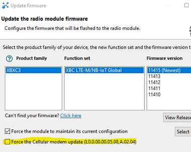
The newest firmware update includes the most recent u-blox update. [L0.0.00.00.05.08 App version 02.04, released 20May19] It requires using USB direct mode, but if you have the XBee3 TH dev board, it’s painless. I recommend updating.
There have been big warnings all over the place for the last several versions saying not to use bypass mode. Yet, despite that, the newest firmware actually includes a new command specifically for adjusting the underlying baud rate while working in bypass mode so we’re definitely not the only ones still using it.
I’m reading and testing more and I’m not so sure that I want to be setting the profile to “1/No Profile/SIM ICCID selected” for a Hologram SIM. While in the part of the documentation for the carrier profile command Digi says to use “1” for no configuration if you’re not connecting, in the steps of the connection process, they recommend this setting for European customers but not Americans. u-blox doesn’t provide any clarity at all on what the different profiles are. When Digi is describing the commands to manually select an LTE bands, they specify that bands can only be manually selected if the carrier profile is set to “1/No Profile.” So I started testing going back and forth between the different profiles using both the Digi commands (CP0-3) and the u-blox commands (UMNOPROF) and using both a Hologram SIM and the T-Mobile SIM I yanked out of my own cell phone. When I use my T-Mobile SIM, setting the carrier profile to either “1/None” in the XBee firmware or setting the UMNOPROF to “1/SIM ICCID select” does indeed make it “figure it out” and on the next reset if I query the profile the response is 5/T-Mobile. The Digi firmware doesn’t apparently doesn’t handle any CP response except 0/1/2/3 so it continues to report “1” but the u-blox has definitely locked on to T-Mobile. But, when using a Hologram SIM, the same magic doesn’t happen. The module can’t figure out what the profile for the SIM should be so it leaves it as whatever it was last selected to be. I was beginning to think that the command was just not working because I couldn’t ever get a response of 1 back to the “UMNOPROF?” command or see any change from it at all until I put in the T-Mobile SIM and saw that it go automatically to 5 after a request of 1. When left in transparent through a couple of resets and setting CP=1, it Digi sets the u-blox profile to 100=standard Europe. I’m strongly suspect that the u-blox “standard European” profile might actually mean “open up all the bands and either manually select the ones you really want or hope your SIM picks one” since Digi specifies that you must use CP=1 if you do want to manually select and u-blox says that selecting a profile will over-write all manual band selection. I’m just not so sure I trust the Hologram SIM to really stay connected when left to its own devices like that. I got most of the boards that had refused to connect to connect again by setting CP to 1, but I don’t know if the success was because I picked 1 or because I changed it at all. After all, all the boards I was messing with were boards that had previously connected and stayed connected for few weeks or months using no carrier profile at all. I think going forward I would prefer to specifically select the AT&T profile unless I know the board will be deployed somewhere with no AT&T signal.
-
2020-02-25 at 2:13 PM #13863
And @mbarney, WRT buying new parts.. I’m still not happy with the failure rate of the XBee’s, but I don’t have any suggestions for anything better.
-
2020-02-25 at 5:11 PM #13864
OK, thank you, Sara! Bummer that there’s no clean solution yet for reliable LTE that’s carrier-agnostic. I suppose that’s asking a lot. 🙂
Matt
-
2020-02-26 at 10:40 AM #13865
Well, setting the profile to ‘1’ might work fine for the long term; I really have no idea. It just makes me a bit nervous.
-
2020-02-28 at 2:08 PM #13870
Re: updating XBee and u-blox firmware, I just noticed the ‘force cell modem update’ checkbox in XCTU defaulted to unchecked. Hadn’t noticed that before… oops. I’ll enable this from now on when updating my modems.
-M
Attachments:
-
2020-03-03 at 11:50 AM #13880
Sara noted above that she re-wrote TinyGsm – so I decided it was a good time to update all my code with new libraries. Trouble is, I can’t get TinyGSM with templates from EnviroDIY GitHub to compile on the Arduino IDE (I’m not using PlatformIO). I’m sure I’m making a simple mistake or compiler option but can’t figure it out being a novice C++ programmer. Here’s the the start of a long list of errors:
In file included from ….\libraries\TinyGSM\src/TinyGsmClientXBee.h:26:0,
from ….\libraries\TinyGSM\src/TinyGsmClient.h:93,
from ….\my_sketch.ino:229:
….\libraries\TinyGSM\src/TinyGsmModem.tpp:15:7: error: ‘TinyGsmModem’ is not a template
class TinyGsmModem {
^~~~~~~~~~~~
In file included from ….\libraries\TinyGSM\src/TinyGsmBattery.tpp:12:0,
from ….\libraries\TinyGSM\src/TinyGsmClientXBee.h:24,
from ….\libraries\TinyGSM\src/TinyGsmClient.h:93,
from …\my_sketch.ino:229:
….\libraries\TinyGSM\src/TinyGsmCommon.h:208:7: note: previous declaration here
class TinyGsmModem
^~~~~~~~~~~~
In file included from ….\libraries\TinyGSM\src/TinyGsmClient.h:93:0,
from ….\my_sketch.ino:229:
….\libraries\TinyGSM\src/TinyGsmClientXBee.h:69:40: error: expected template-name before ‘<‘ token
class TinyGsmXBee : public TinyGsmModem<TinyGsmXBee>,….. -
2020-03-03 at 11:58 AM #13881
Oh dear. I forgot to test on the Arduino IDE. I’ll start looking into it.
-
2020-03-03 at 12:15 PM #13882
I got it to compile on the Arduino IDE, so there’s must be a tangle in your library structure. Can you open the library folder (probably in my documents/arduino if you’re using windows) and look at your folders and make sure you only have one TinyGSM? Can you open the TinyGSM folder and open “TinyGsmCommon.h” and check the version number?
-
2020-03-04 at 10:26 AM #13890
Yep – I had a problem with my library. All is good now. Sorry for the fire drill.
-
2020-03-04 at 10:43 AM #13891
No worries! I should have checked everything out on the Arduino IDE anyway.
-
-
AuthorPosts
- You must be logged in to reply to this topic.