@braedon-dority
Active 1 year, 5 months agoForum Replies Created
-
AuthorPosts
-
@shicks I’m also going to be adding an air temperature sensor that has a 12-volt fan in the radiation shield. The fan can run at lower power by using pulse width modulation. I’m wondering if there might be a way to accomplish this with the power relay, since the fan will have to be connected directly to the battery like the heaters on my other sensors. Is that something that can be done using the Mayfly and the Seeed Studio power relay we’ve discussed here? PWM is new for me, so I’m not exactly sure how that would look trying to control the power consumption of a fan that is not drawing its power from the Mayfly.
@shicks I wanted to run by what my thought process is with these relays and some of the questions I have now that I have purchased a few. I think my questions are general enough that you should be able to help me with them. I am looking to connect the Seeed relay to the D10-D11 grove terminal on the Mayfly. This would connect the relay’s SIG pin to D10 and the NC pin to D11 and supply it with switched 5V power.
There is a Wiki page made by seeed studio (https://wiki.seeedstudio.com/Grove-2-Coil_Latching_Relay/#with-arduino), but I am having a hard time following it because in the sections where they talk about the rising and falling edge of the SIG pin, they mention both the NC and NO states, and it isn’t really clear which state (NC/NO) is associated with edge (rising/falling). When I mess with it on my own, it seems that the NO state occurs when I drive the SIG pin low, and the NC state occurs when I drive the SIG pin high. Is that correct?
I’m not entirely sure how to use the six screw terminals, but my thought is that I would connect the positive terminal of my battery to one of the NO relay terminals (such as 1NO), and then I would connect all of the heater positive leads to the other NO relay terminal (such as 2NO). I would also take all the negative leads of the heaters and connect them straight to the battery ground. I would then turn on the switched power on the Mayfly when my 15-minute mark came up, drive D10 low, and then turn the switched power off. This would turn on the heaters by making the connection between the battery and the heaters’ positive leads. When my data logging was complete for that interval, I would want to turn of the heaters, so I would turn the switched power back on and drive D10 high to close the relay. I could then turn the switched power off until the next 15-minute marker came.
Is this a sound approach to this problem?
This looks like a great option. Thanks Shannon for your help!
I have four sensors with heaters, and combined they draw 61.6 mA.
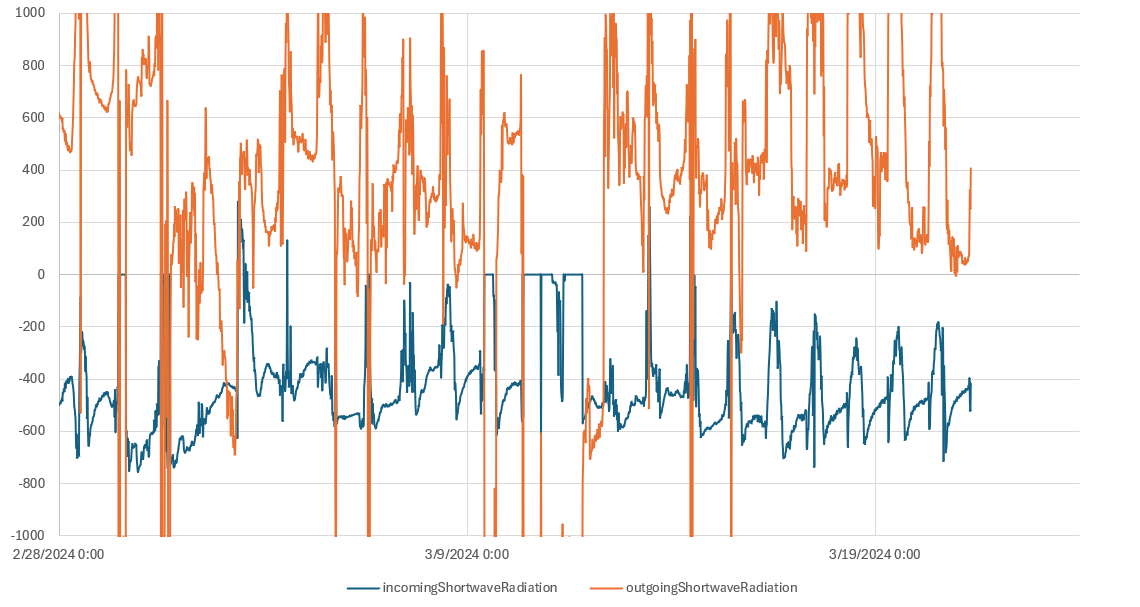
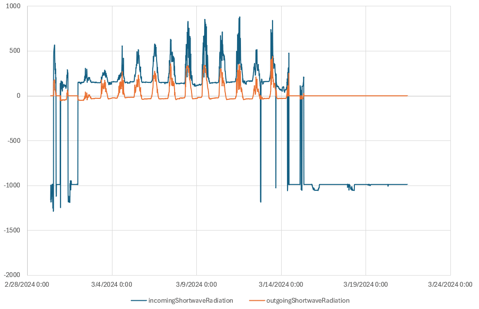
@shicks this is something I am still struggling with, and I am having hard time figuring out. I’ve added some pictures with some of the data I’ve been collecting. It seems that the logger is picking up that there is some diurnal cycle happening, but the values seem to not match what I would expect, or they can be wildly all over the place. If I could get some help with this that would be great.
@srgdamiano do you by chance see where I am going wrong?</p>
Thanks for the quick response Sara. I have not used the build flag. Flags are not something I am familiar with, and I don’t know how to use or adjust them properly. Where would be the appropriate place to make this adjustment in the library?
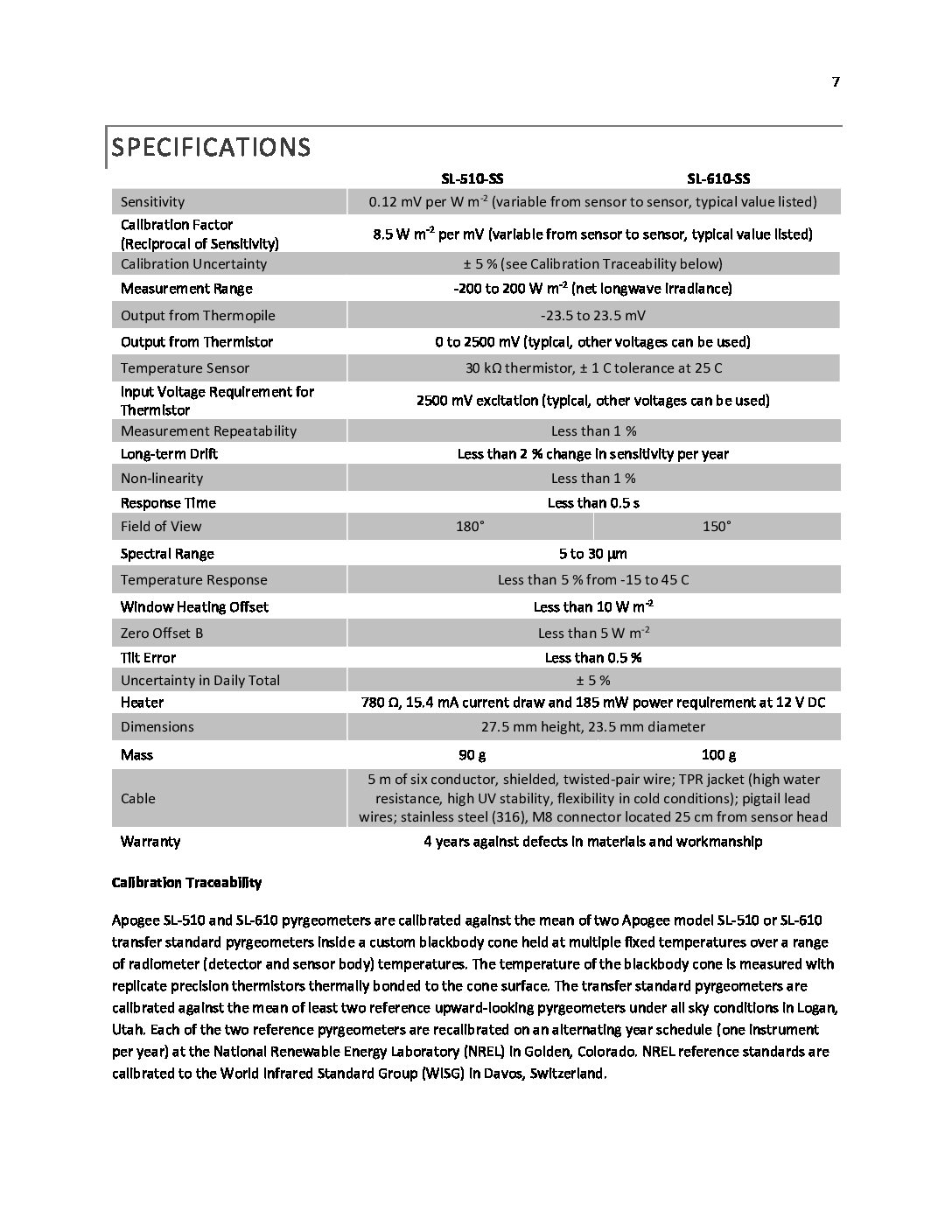
I’ve attached the specs sheet to this reply. Maybe you can help me interpret it. The following is what I was told from Apogee when I asked about the heaters:
“Regarding the heaters, you do not need to operate them all the time. If the sensors are not in an environment where snow/frost are an issue, the connections for the heater can be omitted entirely. So long as the heater connections are in use (yellow wire on the SL-610-SS), the heater will be on. The only way to turn off the heater is to disconnect the corresponding pigtail. Most people leave them on all the time if their datalogger has enough space available. Not using the heater at all will not affect readings. If the heater is constantly powered, it is able to clear frost/snow in just a couple of minutes (depending on how much).”
Since these are snow sensing stations, the heater will be needed, but as far as I understand it, they do not need to be powered constantly. Am I understanding correctly?
Attachments:
Awesome. The XBee module is an RF module, the XBee Pro S3B. I just remembered, while the apogee sensors I am using don’t require power to make measurements, they do require power for the internal heater. The pyrgeometer heaters, according to the datasheet, draw 15.4 mA and 185 mW at 12 VDC. The pyranometers draw 30.8 mA and 370s mW at 12 VDC. In total there are four apogee sensors (two pyrgeometers and two pyranometers). Do you think it is still a similar situation @shicks that the 4400 mAh battery and 5w panels are sufficient?
-
AuthorPosts