
Home › Forums › Mayfly Data Logger › XBee Networks of Mayfly Loggers – 900Mhz
Tagged: 900MHz, modular sensors, ModularSensors, XBee Pro S3B
- This topic has 28 replies, 9 voices, and was last updated 2023-07-13 at 7:12 PM by
 Braedon.
-
AuthorPosts
-
-
2018-10-03 at 5:49 PM #12570
Hi everyone,
I thought that I would start a new thread in case anyone is interested in using their Mayfly loggers in locations where there is not reliable cell service or in areas of dense vegetation.
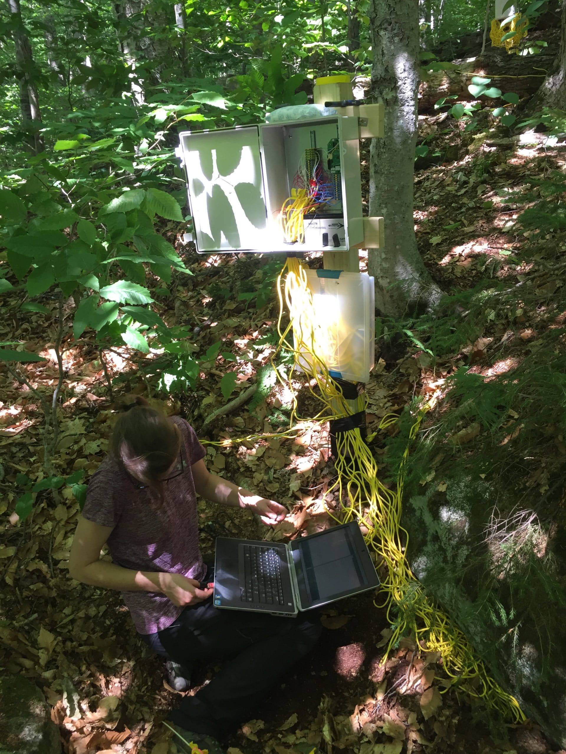
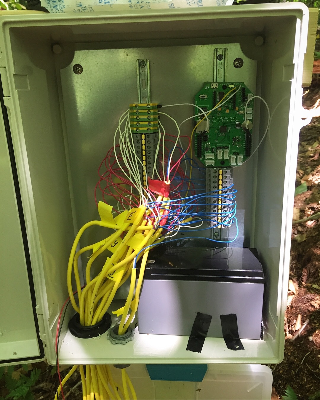
This past summer we (Dartmouth, Plymouth State University) have been working with the US Forest Service to install a sensor network to monitor soil and wood moisture in dead and downed wood at Hubbard Brook research station in the White Mountains of New Hampshire. Ultimately we had 60 or so sensors hooked up to 3 Mayflys in boxes with Din Rails for wiring and large lead-acid batteries for power. We were under tree canopy so solar power wasn’t a particularly good option for us. Some photos attached.
This academic year we’ll be working on expanding our network and hope to utilize the XBee socket to construct a logger network, thereby expanding our collection range. This will definitely come into play when we install similar sensor networks in northern New Hampshire – we’d like to ultimately send signal from a master node to a receiver at our research station where it can be uploaded online for real-time checks of sensor functionality.
My sense is that the current community has predominantly utilizes XBee devices that access mobile networks. Due to vegetation, distance, and slope, my thinking is to go the 900mhz route with an RPSMA antenna. I wonder if anyone has had experience utilizing these types of Bee modules before and/or how compatible they are with the Mayfly. I am guessing that they would work just fine – power draw *might be an issue, but I guess I’ll cross that bridge later.
Any information or thoughts appreciated and I’ll provide updates as we continue to make progress.
Dave
-
2018-10-03 at 7:12 PM #12574
Hi Dave @dartmouthwsn
Yes I’ve been thinking about it, and I have used the XBP900s before.
Do you see that it would gateway to a) building with internet and power, or b) would it be a gateway to a cellular service?I just did a long post about this – but then when I completed I have been logged out somehow the post was lost. ouch.
Will try and reconstruct the post but got to get some other things done.
Neil -
2018-10-03 at 10:46 PM #12575
We have successfully used dozens of Xbee Pro 900HP radios with Mayfly boards for our logger network here at the Stroud Center and at other locations. You can program the modules to be in “pin-sleep mode”, meaning you can toggle the sleep mode by driving a pin high or low. You can also use cyclic sleep and other “smart” sleep methods if you want to implement a mesh network. In our locations, we’re fine with just a central coordinator that stays constantly powered and connected to an ethernet jack. Whatever radio traffic it hears from the sleeping logger nodes, it relays to our online database. I wrote about it earlier this year in another thread: https://www.envirodiy.org/topic/connecting-to-the-internet/
Nowadays you can buy dedicated base station modules that do the same thing as my homemade version, but almost 6 years ago when I first built it, there were very few reliable and affordable options.
The 900MHZ Xbee radios have a much better range in our forested terrain than the 2.4GHZ radios. In open and relatively flat areas, I’ve gotten almost a mile of distance between the logger and the base station. Your results will vary depending on the gain and placement of your antennas, and probably more importantly the topography and forest density. In terms of battery usage, they are very efficient when compared to the cellular modules we use in the hundreds of areas where we don’t have a base station. The radios sleep constantly just like the loggers, and when it’s time for a transmission, they are powered for a fraction of a second and then return to sleep.
I use both the RPSMA modules as well as the U.FL models, depending on what sort of enclosure I’m mounting the Mayfly in.
I use weatherproof bulkhead RPSMA fittings that mount the antenna on the enclosure, and sometimes they are a continuous, 1-piece design with a u.fl connector on the inside end. It also depends on how much physical abuse the radio module is going to see. The RPSMA fittings are much more appropriate if you’ll be moving the board or cables around frequently, since the u.fl connectors are somewhat fragile and finicky, and will fail quickly if you make-break the connection too many times. -
2018-10-04 at 1:58 PM #12577
Wow – nice Shannon,
I was wondering @shicks do you have any references to the XBP900 driver code on the mayfly. Since you’ve put the infrastructure in place be nice to have a starting point :). Thanks for the reference to the Uno. Interesting what you can do on an Uno.
Same observation about 2.4GHz in a forest – the 2.4G gets absorbed by water – ie leaves.
I used two XBP900 in a point-2-multipoint with an Lantronix XPORT AR, that delivered the UART serial data to a destination port – that was then processed into a mysql record.The wire protocol used a TinyOS packet structure which could support a mesh. For a mesh the power usage and network maintenance considerations get more complicated.
The multi-point was a “gateway” that was at buildings that had power and internet access. So from the building antenna position the Line Of Sight for a standard XBP-900HP is about 9miles in a radius from that point – and can support 16bit addressing (65K) end point nodes.
In one location there was a slight ground hump in the way and it was on the edge of the range. I made sure the RSSI was part of the reported signal to be able to monitor it.
There are websites out there that can analyze elevation profile between two points to determine if there is an LOS.Now-days I’m looking at a PocketBeagle with a Ethernet module and POE splitter
PocketBeagle-SC-569
MIKROE-971Attachments:
-
2018-10-25 at 3:05 PM #12611
Shannon,
This is very helpful! We’ve ordered a few XBee PRO S3B 900 modules but are having trouble getting them to communicate via the Mayfly script.
One thing we think may be a problem is whether or not we chose the ‘programmable’ version of the modules. I noticed that Scott had an issue with this in another post from earlier in the Spring, and that he just purchased non-programmable XBees and the situation resolved itself. I’m willing to just purchase those if that makes the difference, but figured it was worthwhile to ask you to see which versions of the 900 modules you had been using successfully.
One thing we’re also not convinced we are doing correctly is adding the proper libraries to the simple sketch you posted before (here). I don’t see any libraries in that and think that also may be an issue.
Do you have any suggestions?
Dave
-
2018-10-26 at 12:51 PM #12616
That simple Xbee serial printing example doesn’t require any additional libraries installed in you IDE or called by your sketch. All it is doing is printing text to the 2 separate hardware serial ports on the Mayfly.
I have never used the programmable versions of the Xbee 900HP. There are infinite combinations of ways to configure an Xbee module and its network, and it gets complicated really fast once you start changing things and adding features. So when I set up my network years ago, I kept it really simple. You first have to program the modules with the X-CTU software before they can be used. I keep them in the same basic configuration that they’re shipped in. Transparent, AT mode, 9600 baud, but I set them as end nodes and not coordinators (my base station is set as the coordinator and never sleeps). The end nodes are set to pin-sleep mode so that the Mayfly wakes them when it’s time to send data. So the Mayfly just drives a pin low (Xbee modules sleep when pin high, and wake when pin low) to wake the module, send it a line of serial text at 9600bd, and the Xbee transmits that line to the coordinator (who’s always awake), and then the Mayfly puts the Xbee back to sleep and then the Mayfly sleeps. I found that sending serial data from the Mayfly to the Xbee module using anything faster than 9600bd will sometimes throw a corrupted character in there occasionally, which messes up the receiving sketch on the coordinator’s UnoEthernet basestation. So it’s best to keep serial communication between the Mayfly and bee modules at the default 9600bd.
-
2019-06-01 at 12:00 PM #12914
The end nodes are set to pin-sleep mode so that the Mayfly wakes them when it’s time to send data. So the Mayfly just drives a pin low (Xbee modules sleep when pin high, and wake when pin low) to wake the module, send it a line of serial text at 9600bd, and the Xbee transmits that line to the coordinator (who’s always awake), and then the Mayfly puts the Xbee back to sleep
Shannon,
Would you be willing to share the code that drives the Xbee pin to low (or high)?Thank you
-
2019-06-07 at 5:59 PM #12917
@jkirchoff – drive the pin level with the digitalWrite(#, level) function.
If you’re using a Mayfly, the XBee’s sleep request pin is attached to the Mayfly pin 23. So to wake the bee, send data, and put it to sleep all you needs is:
digitalWrite(23, HIGH);
Serial1.print(“some text);
// more print statements as desired
digitalWrite(23, LOW);Use XCTU to set your XBee up to use pin sleep. That’s also (by far) the easiest way to test your other radio settings and connectivity before deploying. You could code all the radio setup with the Mayfly, but Digi’s program makes it much, much easier.
-
2019-06-07 at 6:43 PM #12918
Sara,
Thank you so much for your reply. I was just getting ready to try to figure it out. I’ve been having issues with my batteries draining, so this will be a tremendous help.Edited 6/8/19:
After some trial and error, you need to set pin 23 to LOW before transmitting. At least that’s what I could get to work with the xBee’s I’m using.
digitalWrite(23, LOW); wake up the xBee
Serial1.print(“some text);
// more print statements as desired
digitalWrite(23, HIGH); put the xBee to sleep -
2019-06-10 at 6:01 PM #12924
Here’s some sample code that I just put together to demonstrate the code for waking and sleeping the Xbee. You’ll notice it’s a little more complicated than just setting the D23 pin high or low. That’s because the pin should be pulled high when you want to sleep the Xbee (like I mentioned in my previous post), and if you want to sleep the Mayfly (Mayfly sleep function not shown in the code below), you’ll want to enable the input pullup so the Mayfly pin still looks high to the Xbee unit, otherwise when the Mayfly sleeps, the Xbee won’t get the HIGH signal needed to keep it asleep and will therefore wake up.
It’s also a good idea to leave a few seconds before and after your payload transmission to give the Xbee network adequate time to do the behind-the-scenes payload transmission stuff.
Arduino12345678910111213141516171819202122232425262728293031323334353637383940414243#define XBEE_SleepPin 23void setup(){//Initialise the serial connectionSerial.begin(57600);Serial1.begin(9600); //this is the Xbee UART, default Xbee speed is 9600 baudpinMode(8, OUTPUT); //Green LEDpinMode(9, OUTPUT); //Red LEDdigitalWrite(8, HIGH); //turn on the Green LED and leave it ondigitalWrite(9, LOW); //turn off the Red LED, we'll use it later to indicate Xbee wakepinMode(XBEE_SleepPin,OUTPUT); // Set the Xbee "wake-up pin" (D23) to outputdigitalWrite(XBEE_SleepPin,LOW); // wake-up XBee to start withSerial.println("Xbee Testing Sketch");delay(2000);}void loop(){wakeXbee();delay(3000); //give the Xbee a few seconds to wake up and be seen by the networkSerial1.println("This_is_the_xbee_payload"); //this is the text that gets sent via the Xbee RF moduledelay(3000); //give the Xbee a few seconds before putting it back to sleepsleepXbee();delay(10000); // wait 10 seconds, then do it all over again}void sleepXbee(){Serial.println("Putting the Xbee to sleep");delay(100);pinMode(XBEE_SleepPin,INPUT_PULLUP); // Set the "wake-up pin" to input and enable the internal pullupdigitalWrite(XBEE_SleepPin,HIGH); //put the Xbee to sleepdigitalWrite(9, LOW); //turn off the RED LED when the Xbee is asleep}void wakeXbee() {Serial.println("Wake up the Xbee");delay(100);pinMode(XBEE_SleepPin,OUTPUT); // Set the "wake-up pin" to outputdigitalWrite(XBEE_SleepPin,LOW); // wake-up XBeedigitalWrite(9, HIGH); // turn on the RED LED when the Xbee is awake}
-
-
2018-10-04 at 7:52 PM #12583
Had this come through –
https://www.crowdsupply.com/silicognition/wesp32 – POE ESP supposedly first delivery mid-Dec
https://github.com/espressif/arduino-esp32 No idea how well an Arduino XBP900 interface would work with this.I personally have found PoE 802.15af has worked very well for “borrowing” some space on some other entities building.
It has meant a long drill for going through an insulated wall, and physical access to the network somewhere in the building. Building maintenance is used to being helpful. It has been easier than IT WiFi access that is nervous about network breaches, and changing passwords. -
2019-07-10 at 4:15 PM #12968
Hi Everyone,
I’m working with @dartmouthwsn, the original poster on this thread, to construct a logger network using Mayflys and 900 Mhz XBee Pros. We had the code successfully working so that the logger Mayflys were able to send data to a centrally located node using the Xbee Pros. The code has been functional for several months and was tested at several sites over varying distances with dependable and consistent results.
However, about a week ago, we ran into an issue with the code. The central Mayfly node receiving the data no longer consistently writes the data to its SD card or prints it to the serial. I’ve tried using different Mayflys as well as resetting the Mayflys. Though the code has gone through many iterations, even the original working code no longer functions for the receiving node.
Oddly enough, changing the baud rate of the XBee receiving data seems to work for a few uploads of the code––after changing the baud rate, the data is successfully collected for about three or four uploads of the code and then suddenly stops working again. Looking at the XBee’s serial in XCTU, I can see that all of the data is actually being received by the XBee, but not written to the SD card.
As far as I can tell, I think the issue is that, for some reason, the XBee serial is not recognized as being available despite the fact that the XBee is receiving data. I’ve tried re-downloading the libraries, thinking that my SoftwareSerial library may have been out-of-date, but nothing seems to fix the issue.
I’m wondering if anyone has run into a similar problem, and if anyone has any advice on how to solve the issue.
Any help would be greatly appreciated!Emma
-
2019-11-26 at 12:21 PM #13401
Hello Everyone,
I am part of the Little Manistee Watershed Conservation Council here in North West Michigan. We are in the early stages of implementing a series of up to six monitoring stations along 72 river miles on the Little Manistee River. All stations will have CTD and at least one will have a Turbidity sensor. This conversation caught my attention because cell coverage in this area is very unreliable and I believe to make the Mayfly stations upload reliably the only choice is the xbee radio and not cell.
My plan for the first unit is to use xbee radio from the monitoring station to a base station in my house that will connect to the internet via an ethernet connection to my router and satellite. I expect the satellite system to be problematic, but it is my only choice here in the forest. The future additional units will either use the same configuration at other citizen scientists homes or connect as second or third nodes to existing base stations.
I am in the process of purchasing materials for the first unit. I was hoping for suggestions on the base station configuration and the radio modules.
For the base station it would appear an Uno with Ethernet and Xbee shields would serve the purpose with some programming. The Arduino Ethernet Shannon refers to in the link above shows it is retired with no newer version I can find. I have not been able to find a better alternative and am wondering if any of you have?
There are so many xbee radio modules out there it is overwhelming. We are in dense pine and oak forest and the monitoring stations will be in river valleys so the 900 MHZ xbee modules with external antennas are probably the place to start. Some monitors will be close to base stations, others will not. From reading the conversation above it sounds like I should use a non programmable radio module. Can any of you tell me what specific modules you have had success with and other parameters I should be considering based on your experience?
-
2020-06-18 at 11:01 AM #14256
Hi everyone,
Some updates on this project – we now have 12 loggers monitoring 8 sensors at each site. It took a full field season but now have all the wiring free of shorts and power problems. We have mostly been focused on the data collection side and, because of COVID, don’t have resources to work solely on the 900Mhz radio network element quite yet – we had some success transferring data along the network, but path loss did not allow us to collect from all nodes in the network.
-
2021-05-25 at 10:57 AM #15569
Hi there! I’m hoping to do something similar to what David is doing. I’m using a couple Xbee Pro 900HP modules and couple Mayfly’s. I’m setting up the network using PlatformIO and the Monitoring Station Manual, and I came across a roadblock when I updated the code with some of the Xbee lines. The code runs, printing data to the Mayfly’s SD card until I add the the Xbee code to the loop(). Once I added the Xbee code, the SD card printing prompts don’t pop up in the Serial Monitor (only the “Wake up the Xbee” and “Putting the Xbee to sleep” prompts).
I feel like it’s an ordering issue in the loop() from when I updated the code, but I’m not sure. Any help is greatly appreciated! Thanks!
Also, while I’m here, I also have been struggling on how to take the sensor measurements that are printed to the SD card and communicate them to the Xbee (with the Serial1.println() line in the loop() command). I’m pretty new to Arduino programming, so I feel like I’m probably overcomplicating it.
/** =========================================================================
* @file DRWI_NoCellular.ino
* @brief Example for DRWI CitSci without cellular service.
*
* @author Sara Geleskie Damiano <sdamiano@stroudcenter.org>
* @copyright (c) 2017-2020 Stroud Water Research Center (SWRC)
* and the EnviroDIY Development Team
* This example is published under the BSD-3 license.
*
* Build Environment: Visual Studios Code with PlatformIO
* Hardware Platform: EnviroDIY Mayfly Arduino Datalogger
*
* DISCLAIMER:
* THIS CODE IS PROVIDED “AS IS” – NO WARRANTY IS GIVEN.
* ======================================================================= */// ==========================================================================
// Include the libraries required for any data logger
// ==========================================================================
/** Start [includes] */
// The Arduino library is needed for every Arduino program.
#include <Arduino.h>// EnableInterrupt is used by ModularSensors for external and pin change
// interrupts and must be explicitly included in the main program.
#include <EnableInterrupt.h>// To get all of the base classes for ModularSensors, include LoggerBase.
// NOTE: Individual sensor definitions must be included separately.
#include <LoggerBase.h>
/** End [includes] *///Defines the XBEE Sleep pin
#define XBEE_SleepPin 23// ==========================================================================
// Data Logging Options
// ==========================================================================
/** Start [logging_options] */
// The name of this program file
const char* sketchName = “sensor_test.ino”;
// Logger ID, also becomes the prefix for the name of the data file on SD card
const char* LoggerID = “XXXXX”;
// How frequently (in minutes) to log data
const uint8_t loggingInterval = 1;
// Your logger’s timezone.
const int8_t timeZone = -5; // Eastern Standard Time
// NOTE: Daylight savings time will not be applied! Please use standard time!// Set the input and output pins for the logger
// NOTE: Use -1 for pins that do not apply
const int32_t serialBaud = 115200; // Baud rate for debugging
const int8_t greenLED = 8; // Pin for the green LED
const int8_t redLED = 9; // Pin for the red LED
const int8_t buttonPin = 21; // Pin for debugging mode (ie, button pin)
const int8_t wakePin = A7; // MCU interrupt/alarm pin to wake from sleep
// Set the wake pin to -1 if you do not want the main processor to sleep.
// In a SAMD system where you are using the built-in rtc, set wakePin to 1
const int8_t sdCardPwrPin = -1; // MCU SD card power pin
const int8_t sdCardSSPin = 12; // SD card chip select/slave select pin
const int8_t sensorPowerPin = 22; // MCU pin controlling main sensor power
/** End [logging_options] */// ==========================================================================
// Using the Processor as a Sensor
// ==========================================================================
/** Start [processor_sensor] */
#include <sensors/ProcessorStats.h>// Create the main processor chip “sensor” – for general metadata
const char* mcuBoardVersion = “v0.5b”;
ProcessorStats mcuBoard(mcuBoardVersion);
/** End [processor_sensor] */// ==========================================================================
// Maxim DS3231 RTC (Real Time Clock)
// ==========================================================================
/** Start [ds3231] */
#include <sensors/MaximDS3231.h>// Create a DS3231 sensor object
MaximDS3231 ds3231(1);
/** End [ds3231] */// ==========================================================================
// Campbell OBS 3 / OBS 3+ Analog Turbidity Sensor
// ==========================================================================
/** Start [obs3] */
#include <sensors/CampbellOBS3.h>const int8_t OBS3Power = sensorPowerPin; // Power pin (-1 if unconnected)
const uint8_t OBS3NumberReadings = 10;
const uint8_t ADSi2c_addr = 0x48; // The I2C address of the ADS1115 ADC
// Campbell OBS 3+ *Low* Range Calibration in Volts
const int8_t OBSLowADSChannel = 0; // ADS channel for *low* range output
const float OBSLow_A = 0.000E+00; // “A” value (X^2) [*low* range]
const float OBSLow_B = 1.000E+00; // “B” value (X) [*low* range]
const float OBSLow_C = 0.000E+00; // “C” value [*low* range]// Create a Campbell OBS3+ *low* range sensor object
CampbellOBS3 osb3low(OBS3Power, OBSLowADSChannel, OBSLow_A, OBSLow_B, OBSLow_C,
ADSi2c_addr, OBS3NumberReadings);// Campbell OBS 3+ *High* Range Calibration in Volts
const int8_t OBSHighADSChannel = 1; // ADS channel for *high* range output
const float OBSHigh_A = 0.000E+00; // “A” value (X^2) [*high* range]
const float OBSHigh_B = 1.000E+00; // “B” value (X) [*high* range]
const float OBSHigh_C = 0.000E+00; // “C” value [*high* range]// Create a Campbell OBS3+ *high* range sensor object
CampbellOBS3 osb3high(OBS3Power, OBSHighADSChannel, OBSHigh_A, OBSHigh_B,
OBSHigh_C, ADSi2c_addr, OBS3NumberReadings);
/** End [obs3] */// ==========================================================================
// Meter Hydros 21 Conductivity, Temperature, and Depth Sensor
// ==========================================================================
/** Start [decagon_ctd] */
#include <sensors/DecagonCTD.h>const char* CTDSDI12address = “1”; // The SDI-12 Address of the CTD
const uint8_t CTDNumberReadings = 6; // The number of readings to average
const int8_t SDI12Power = sensorPowerPin; // Power pin (-1 if unconnected)
const int8_t SDI12Data = 7; // The SDI12 data pin// Create a Decagon CTD sensor object
DecagonCTD ctd(*CTDSDI12address, SDI12Power, SDI12Data, CTDNumberReadings);
/** End [decagon_ctd] */// ==========================================================================
// Creating the Variable Array[s] and Filling with Variable Objects
// ==========================================================================
/** Start [variable_arrays] */
Variable* variableList[] = {
new DecagonCTD_Cond(&ctd),
new DecagonCTD_Temp(&ctd),
new DecagonCTD_Depth(&ctd),
new CampbellOBS3_Turbidity(&osb3low, “”, “TurbLow”),
new CampbellOBS3_Turbidity(&osb3high, “”, “TurbHigh”),
new ProcessorStats_Battery(&mcuBoard),
new MaximDS3231_Temp(&ds3231),
};// All UUID’s, device registration, and sampling feature information can be
// pasted directly from Monitor My Watershed. To get the list, click the “View
// token UUID list” button on the upper right of the site page.
// Even if not publishing live data, this is needed so the logger file will be
// “drag-and-drop” ready for manual upload to the portal.// *** CAUTION — CAUTION — CAUTION — CAUTION — CAUTION ***
// Check the order of your variables in the variable list!!!
// Be VERY certain that they match the order of your UUID’s!
// Rearrange the variables in the variable list if necessary to match!
// *** CAUTION — CAUTION — CAUTION — CAUTION — CAUTION ***
const char* UUIDs[] = {
“12345678-abcd-1234-ef00-1234567890ab”, // Electrical conductivity
// (Decagon_CTD-10_Cond)
“12345678-abcd-1234-ef00-1234567890ab”, // Temperature
// (Decagon_CTD-10_Temp)
“12345678-abcd-1234-ef00-1234567890ab”, // Water depth
// (Decagon_CTD-10_Depth)
“12345678-abcd-1234-ef00-1234567890ab”, // Turbidity (Campbell_OBS3_Turb)
“12345678-abcd-1234-ef00-1234567890ab”, // Turbidity (Campbell_OBS3_Turb)
“12345678-abcd-1234-ef00-1234567890ab”, // Battery voltage
// (EnviroDIY_Mayfly_Batt)
“12345678-abcd-1234-ef00-1234567890ab” // Temperature
// (EnviroDIY_Mayfly_Temp)
};
const char* registrationToken =
“12345678-abcd-1234-ef00-1234567890ab”; // Device registration token
const char* samplingFeature =
“12345678-abcd-1234-ef00-1234567890ab”; // Sampling feature UUID// Count up the number of pointers in the array
int variableCount = sizeof(variableList) / sizeof(variableList[0]);// Create the VariableArray object
VariableArray varArray(variableCount, variableList, UUIDs);
/** End [variable_arrays] */// ==========================================================================
// The Logger Object[s]
// ==========================================================================
/** Start [loggers] */
// Create a new logger instance
Logger dataLogger(LoggerID, loggingInterval, &varArray);
/** End [loggers] */// ==========================================================================
// Working Functions
// ==========================================================================
/** Start [working_functions] */
// Flashes the LED’s on the primary board
void greenredflash(uint8_t numFlash = 4, uint8_t rate = 75) {
for (uint8_t i = 0; i < numFlash; i++) {
digitalWrite(greenLED, HIGH);
digitalWrite(redLED, LOW);
delay(rate);
digitalWrite(greenLED, LOW);
digitalWrite(redLED, HIGH);
delay(rate);
}
digitalWrite(redLED, LOW);
}// Reads the battery voltage
// NOTE: This will actually return the battery level from the previous update!
float getBatteryVoltage() {
if (mcuBoard.sensorValues[0] == -9999) mcuBoard.update();
return mcuBoard.sensorValues[0];
}
/** End [working_functions] */// ==========================================================================
// Arduino Setup Function
// ==========================================================================
/** Start [setup] */
void setup() {
// Start the primary serial connection
Serial.begin(serialBaud);//Sets up the baud rate for the XBEE
Serial1.begin(9600);// Print a start-up note to the first serial port
Serial.print(F(“Now running “));
Serial.print(sketchName);
Serial.print(F(” on Logger “));
Serial.println(LoggerID);
Serial.println();Serial.print(F(“Using ModularSensors Library version “));
Serial.println(MODULAR_SENSORS_VERSION);// Set up pins for the LED’s
pinMode(greenLED, OUTPUT);
digitalWrite(greenLED, LOW);
pinMode(redLED, OUTPUT);
digitalWrite(redLED, LOW);//Sets up pins for the XBEE
pinMode(XBEE_SleepPin,OUTPUT); //Setting XBEE sleep pin as an output
digitalWrite(XBEE_SleepPin, LOW); //Start with XBEE awake
Serial.println(“Xbee is now set up”);
delay(2000);// Blink the LEDs to show the board is on and starting up
greenredflash();// Set the timezones for the logger/data and the RTC
// Logging in the given time zone
Logger::setLoggerTimeZone(timeZone);
// It is STRONGLY RECOMMENDED that you set the RTC to be in UTC (UTC+0)
Logger::setRTCTimeZone(0);// Attach information pins to the logger
dataLogger.setLoggerPins(wakePin, sdCardSSPin, sdCardPwrPin, buttonPin,
greenLED);
dataLogger.setSamplingFeatureUUID(samplingFeature);// Begin the logger
dataLogger.begin();// Note: Please change these battery voltages to match your battery
// Set up the sensors, except at lowest battery level
if (getBatteryVoltage() > 3.4) {
Serial.println(F(“Setting up sensors…”));
varArray.setupSensors();
}// Create the log file, adding the default header to it
// Do this last so we have the best chance of getting the time correct and
// all sensor names correct
// Writing to the SD card can be power intensive, so if we’re skipping
// the sensor setup we’ll skip this too.
if (getBatteryVoltage() > 3.4) {
Serial.println(F(“Setting up file on SD card”));
dataLogger.turnOnSDcard(
true); // true = wait for card to settle after power up
dataLogger.createLogFile(true); // true = write a new header
dataLogger.turnOffSDcard(
true); // true = wait for internal housekeeping after write
}// Call the processor sleep
Serial.println(F(“Putting processor to sleep\n”));
dataLogger.systemSleep();
}
/** End [setup] */// ==========================================================================
// Arduino Loop Function
// ==========================================================================
/** Start [loop] */
// Use this short loop for simple data logging and sending
void loop() {
// Note: Please change these battery voltages to match your battery
// At very low battery, just go back to sleep
if (getBatteryVoltage() < 3.4) {
dataLogger.systemSleep();
}
// If the battery is OK, log data
else {
wakeXbee(); //Wakes up XBEE
delay(3000); //Gives XBEE time to be seen by the network
Serial1.println(); //Text being sent by XBEE module
delay(3000); //Gives XBEE a bit before sending it back to sleep
sleepXbee(); //Puts Xbee to sleepdelay(10000); //wait 10 seconds, then repeat loop
dataLogger.logData();}
}void sleepXbee() {
Serial.println(“Putting the Xbee to sleep”);
delay(100);
pinMode(XBEE_SleepPin,INPUT_PULLUP); // Set the “wake-up pin” to input and enable the internal pullup
digitalWrite(XBEE_SleepPin,HIGH); //put the Xbee to sleep
digitalWrite(9, LOW); //turn off the RED LED when the Xbee is asleep
}void wakeXbee() {
Serial.println(“Wake up the Xbee”);
delay(100);
pinMode(XBEE_SleepPin,OUTPUT); // Set the “wake-up pin” to output
digitalWrite(XBEE_SleepPin,LOW); // wake-up XBee
digitalWrite(9, HIGH); // turn on the RED LED when the Xbee is awake
}
/** End [loop] */ -
2023-05-31 at 4:10 PM #17858
Hello, I am new to using Mayflies and XBee modules, so I’m hoping I can get some help here since the modules I’m planning on using are the 900 MHz XBee Pro S3B. Programming the modules correctly in the XTCU is something I don’t entirely grasp, but for the moment I will focus on programming the Mayfly.
Right now I am just trying to get two Mayflies to send/receive temperature measurements from the Mayfly’s built-in temperature sensor. This first bit of code is for the Mayfly making the measurement and sending the data. The green LED (pin 8) is just so I can easily tell that the Mayfly is running the loop when I have it plugged into a wall.
123456789101112131415161718192021222324#include <Wire.h>#include "Sodaq_DS3231.h"void setup(){Serial1.begin(9600);Wire.begin();rtc.begin();}void loop(){digitalWrite(8, HIGH);rtc.convertTemperature();Serial1.print(rtc.getTemperature());Serial1.println(" deg C");delay(1000);digitalWrite(8, LOW);delay(1000);}This next bit of code is for the Mayfly receiving the data and then printing it to the serial monitor so that I can verify that it is indeed receiving the data.
12345678910111213#include <Wire.h>void setup(){Serial.begin(57600);Serial1.begin(9600);}void loop(){Serial.println(Serial1.read());delay(250);}Right now my serial monitor just prints out a bunch of -1 values. Any help is appreciated. Thanks!
-
2023-05-31 at 7:17 PM #17860
The Bee socket of the Mayfly board isn’t powered continuously by default, so in your code examples above, it appears that you’re not turning them on. If you study the schematic for whichever hardware version of the Mayfly you have, you’ll see that you either have to activate the power to the bee socket’s regulator by setting Mayfly pin D18 high in your code, or modify the Mayfly solder jumper SJ18 from the default D18 position to the 3.3v position for continuous power (there’s instructions for that on the Mayfly Jumper Settings page).
You can also close SJ16 so you’ll see a white LED on the Mayfly whenever the bee socket is powered, and you can close SJ17 to see a blue LED that indicates bee network status (if you’ve configured your xbee modules to show network status on the bee IO5).
-
2023-06-01 at 12:55 PM #17861
Okay, so this is what I have now for my sender code:
1234567891011121314151617181920212223242526#include <Wire.h>#include "Sodaq_DS3231.h"void setup(){pinMode(18, OUTPUT);digitalWrite(18, HIGH);Serial1.begin(9600);Wire.begin();rtc.begin();delay(3000);}void loop(){digitalWrite(8, HIGH);rtc.convertTemperature();Serial1.print(rtc.getTemperature());Serial1.println(" deg C");delay(1000);digitalWrite(8, LOW);delay(1000);}And this is what I have for my receiver code:
1234567891011121314151617#include <Wire.h>void setup(){pinMode(18, OUTPUT);digitalWrite(18, HIGH);Serial.begin(57600);Serial1.begin(9600);delay(100);delay(3000);}void loop(){Serial.println(Serial1.read());delay(3000);}I am still getting a -1 value printed to my serial port. If everything looks right on the coding side of it, then maybe I just need to double-check/reconfigure the modules in XCTU.
-
-
2023-05-31 at 6:52 PM #17859
Gosh Brandon, I successfully used the 900Mhz modules about 15years ago with the TinyOS framework.
Seems you are thinking of using it in a Peer-2-peer arrangement, possibly in a mesh configuration. A lot of options.
I wonder what your back ground is – cause its sort of like jumping into the deep end, and you may wanna flesh out your plan – what your basic intent is. Is there any reason XBee Pro S3B, and not a LoRa in a peer to peer? (Digi XBee LR).
From what I remember, for some of the Xbee’s you can configure in a point to point mode, and then it looks like you are sending data down a wire. The critical issue is that through the XCTU you configure two units to look like a wire – start with XCTU and data sheet of the devices. Of course if you are sending in JSON one end , then you need to have a JSON parser the other end. So that means you want to design your JSON packet. Of course JSON is bulky and thats where if you use the simplest binary numbers, it could fit in a LoRa packet, thats why I bring up the differences.
-
2023-06-01 at 2:58 PM #17862
I am very new to the world of electronics and circuit boards. I am a graduate student of civil engineering looking to deploy snow sensing stations using the Mayfly. They will be satellite stations around an existing piece of infrastructure that already has radio communication set up with Campbell Scientific data loggers. I don’t think the network needs to be anything too advanced. I believe I just need communication between two RF modules, sending data from the satellite station to the Campbell Scientific data logger. I’ve been reading manuals and watching videos, and they have been helpful, but it’s easy to get lost in the sea of information when you are just starting out.
The XBee Pro S3B is just what I have at the moment. I am not familiar with all the differences in modules and what the advantages and disadvantages are.
-
-
2023-06-01 at 3:45 PM #17863
Hey thanks for the overview. Welcome to the art of jumping in – and learning by doing (my philosophy though I’m an EE graduate) – though its beneficial to bring an engineering basis to analyzing the components, and then plug the components together. The engineering basis can be thought of as a technical story – though for EE graduates we talk about engineering requirements.
I’d suggest looking at how to interface to the Campbell Scientific – that is can you inject some dimension less numbers in some fashion and have it come out the other side somewhere that can be used. Maybe other people know more about it, than I do – but you may want the specific model numbers. I looked at trying to work with a 20yr old CS recently, and concluded it really needed a whole new upgrade – and actually finding the satellite channels for even an upgrade was going to be one challenge.
At the simplest level, if you have some Analog inputs available on the Campbell scientific, then it could be case of “extending” those inputs remotely, and scaling the input voltage to your snow depth units.
So then on the snow depth sensor, how does the sensor present its measurement – from other posts on the board it seems you are trying to measure some voltages, so may be that is the snow depth measurement. So then what is the range of the depth measurement. you want to make and what is the dynamic range and resolution on the sensor. That is the sensor might have a dynamic range of 3meter with an accuracy of +/10cm, but actually you are only interested in if there is 0-5cm increase of snow in a 1hour period.
Maybe some other people have better insights – but that would be my first guess at defining what you want to achieve
-
2023-06-26 at 4:05 PM #17934
Can a 900 MHz XBee radio be used with the ModularSensors library? I noticed that there is are DigiXBee.cpp and DigiXBee.h files in the modems folder. Can modem objects created with that class be used with the logAndPublishData() function found in most ModularSensor examples that use XBees, or is there a different way of integrating 900 MHz XBee radios with ModularSensors?
-
2023-07-06 at 12:57 PM #17964
@srgdamiano would you know if the XBee Pro S3B modules can be used with the ModularSensors library? I know how to send data over them using Serial1.print(), but I would like to use these 900 MHz modules with ModularSensors if that is possible. Thanks!
-
-
2023-07-06 at 1:47 PM #17965
The radio XBee’s *cannot* be used directly with the logAndPublishData functions. That only works for XBees that have a direct internet connection.
You would have to set up your radio using the Digi software and then write your loop function, which would print your json or csv string out over the serial port for the radio to hear.
-
2023-07-06 at 2:17 PM #17967
Okay, so what do you think would be the best way to pull out the data generated from the logger object’s logData()? If it is easy to access it, then I feel it shouldn’t be too hard to just jump to a Serial1.print() statement once the logData() method is complete to send the data. Am I thinking this through correctly?
-
2023-07-13 at 7:12 PM #17976
For anyone who would be interested in using these radio modules with modular sensors, I was able to transfer modular sensor readings from a Mayfly through the XBee Pro S3B to another XBee Pro S3B in transparent mode using the following lines of code in my void loop() function:
12345digitalWrite(xbeeSleepPin, LOW);delay(100);dataLogger.printSensorDataCSV(&Serial1);delay(100);digitalWrite(xbeeSleepPin, HIGH);Here, dataLogger is just the Logger object. The xbeeSleepPin is 23. I also used the following lines of code in my setup() function:
1234567// Setup XBeepinMode(xbeeRegulatorPin, OUTPUT);pinMode(xbeeSleepPin, OUTPUT);digitalWrite(xbeeRegulatorPin, HIGH); // Supply power to the XBee regulatorSerial1.begin(xbeeBaud); // Begin UART-1 communicationWire.begin();digitalWrite(xbeeSleepPin, HIGH); // Put XBee in sleep modeThe xbeeRegulatorPin is 18, and the xbeeBaud is 9600.
-
-
-
2023-07-06 at 2:06 PM #17966
@braedon-dority I would add that the Digi range of modems is extensive- with many functions. They have good “Data Sheets” on their capabilities.
What it sounds like you are asking is can two S3Bs be setup like a “wire” – a link for two S3Bs – a peer-two-peer (P2P) link.
That is “print” an ASCII serial string to an S3B over the UART and have it come out another S3B uart.I am afraid its looking at the manual to see if this can be done for the particular model, and follow the examples they give in the manual.
Like a vehicle – for exact technical capabilities dig into the manual
I know some of the 900Mhz models I looked at could do it. However, as its wireless also look at under what conditions it might loose parts the string Good luck.
-
2023-07-06 at 2:25 PM #17968
Yes, these two modules can be set up like a wire. I got a Mayfly to send information over the Pro S3B module to another module connected to a computer. I set them up on the XCTU in transparent mode, set the network IDs to be the same, and told the sender XBee what the serial address is of the receiver XBee. In transparent mode, anytime data is printed to the UART it is automatically sent out of the radio, which is all I really need for the time being. My main question is how to bridge the gap between 900 MHz radio modules and the modular sensors library.
-
-
2023-07-06 at 3:25 PM #17969
@braedon-dority it seems to me you have “bridged” or wirelessly connected one S3B/Mayfly1 to another S3B(XCTU or Mayfly2) and proved the data connection.
A vehicle represents a number of parts that hang together ~ ModularSensors represents a number of Classes that hang together – the value of open source is you can modify the programs/Classes.
However that implies you’ve launched off on your own – so phrasing your question right, 🙂 becomes something you are trying to refine?.
Based on your previous application environment, It seems like you might be asking, “how do I receive the data on Mayfly2 and push it to the .csv file?”
-
-
AuthorPosts

- You must be logged in to reply to this topic.