
 Welcome to EnviroDIY, a community for do-it-yourself environmental science and monitoring. EnviroDIY is part of
 Home › Forums › Mayfly Data Logger › Negative turbidity readings
- This topic has 3 replies, 2 voices, and was last updated 2026-08-17 at 1:16 PM by
 Shannon Hicks.
-
AuthorPosts
-
-
2026-08-10 at 6:11 PM #19776
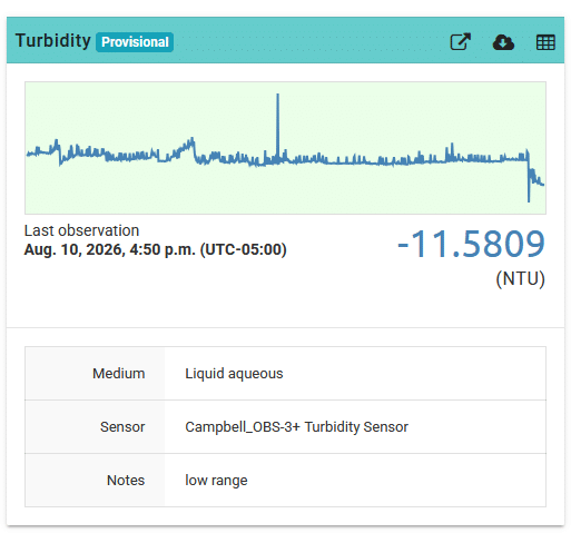
I am noticing negative turbidity readings (https://monitormywatershed.org/sites/NJJC1S/). The turbidity sensor is clean and is situated freely in the water column. I unplugged and replugged the turbidity’s grove cable. Everything in the logger box looks dry and fine. Is my sensor dead or are there other troubleshooting steps I should do? thank you.
Attachments:
-
2026-08-11 at 11:40 AM #19779
Those old Campbell OBS3+ turbidity sensors will either flatline or go negative when they fail. We started deploying dozens of that sensor model about 8 or 9 years ago and almost all of them have been removed from the field in the past few years due to failure. It looks like your station is 8 years old so you got more life out of it than most. To double-check that the sensor really is bad, you can put the Mayfly logger into continuous testing mode by pressing the D21 button, so that the sensors stay powered continuously for a few minutes. Use a voltmeter to check the 5v output supply voltage of the Mayfly board, using the Vcc and Gnd pins of the screw terminal board that the turbidity sensor is connected to. You should see around 5v when the sensor is being powered. If not, your Mayfly board isn’t generating the 5v signal to power the sensor, or the sensor is drawing too much power (usually due to flooding of the sensor housing) so it is shorting out and causing a voltage sag on the supply. You can also check the signal output voltage of the sensor by looking at the two sensor signal wires on the screw terminal board (test them individually, so measure across S1 and Gnd, then S2 and Gnd.) Because I built and installed that particular station you’re referring to, I still have the voltage-to-NTU conversion calibration sheet from the manufacturer so I can send you the equations the logger uses to convert the raw analog voltage readings to NTU. If you manually calculate the turbidity different than what the Mayfly is calculating, then it could possibly be the analog-to-digital converted on your logger board has gone bad, but this is rare. It’s more likely that the sensor has simply died, but since Campbell doesn’t repair these anymore, you only option would be to replace it with something like the newer ClariVue turbidity sensor.
-
2026-08-14 at 5:48 PM #19783
Thank you for the information. I will try the voltmeter for confirmation.
Can a 7-year-old OBS3+ turb sensor go bad if it has been sitting in a climate-controlled room? It was probably used only a couple of times for testing indoors but has been powered off for at least 6 years. I get a positive reading when exposed in the open air, but when I cover it with a towel, I get a negative reading. I’m getting similar results with two different mayfly logger boards, so I think I can rule out a bad analog-to-digital converter.
Do you have a recommendation for connecting a OBS3+ turb sensor to the current Multipurpose 6-pin Screw Terminal Grove Adapter?
I have the white cable (high range signal) going to S2, blue (low range) to S1, red (power) to V+. Since there are only 2 grounds on the current grove adapter, how should I plug in the green, black, and clear wires? Should the black (power ground) go into the V+ slot?
And just to confirm the OBS3+ jumper is set at 5V in the Auxiliary ADC Grove connector while the ClariVue10 jumper is set at 12V in the Digital pin Grove connector.
-
2026-08-17 at 1:16 PM #19784
The shield wire of the OBS3 sensor cable doesn’t actually connect to anything on the sensor, so it’s okay to leave that floating, especially if you’re just testing the sensor. The green and black wires both definitely need to be connected to GND or the sensor won’t work properly. Both the high range and low range should read around 0 NTU when the sensor is in air (assuming the sensor is clean and not pointing at any objects). You should also not test it near sunlight (out of the water) because the light from the sun will interfere with the sensor’s IR input and you’ll get extremely inaccurate results. Placing a dark object like a towel or a boot or a glove over the sensor will give inconsistent results since the IR reflectivity of different color objects will give different readings. We found that using a piece of white paper or a bare hand about an inch away from the sensor is a good way to see if you get full-scale readings from the two sensor outputs. Using a voltmeter, you should see around 2.5v for both sensor output wires when you do this. With nothing near the sensor, you should see very close to 0v on both channels. (Be sure to check that you’re getting 5v from the Mayfly on the V+ line of the screw terminal too).
-
-
AuthorPosts

- You must be logged in to reply to this topic.