
Details and Specifications of the EnviroDIY Mayfly Data Logger v1.0 & v1.1
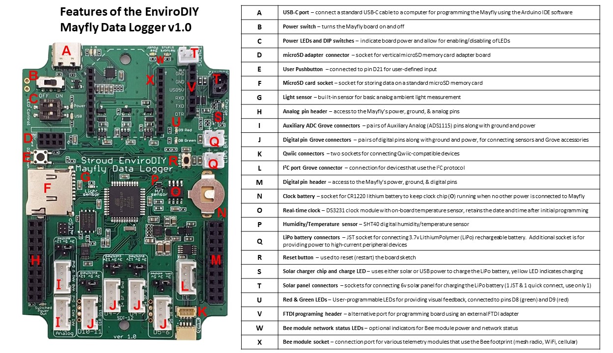
A – USB-C port: for connecting a standard USB-C cable between the Mayfly board and a computer for programming. Can also be used to power the board with any 5v power source (like a cellphone charger)
B- Power switch: simple on-off slide switch for controlling the board power state. Located next to the power switch are 2 unpopulated header holes for connecting a remote power switch if you want to toggle the board power another external switch.
C- Power LEDs and DIP switches: LEDs indicate board power (green) and USB power (orange). Useful for easily seeing if the board is on and if USB power is connected. Green LED will be lit anytime the board has power and the power switch is in the ON position. Orange LED will be lit anytime power is being supplied through the USB or FTDI connectors. If Mayfly board is deployed in a sleeping logger station, it is recommended to set both DIP switches to the OFF position in order to save battery power. Use a small pointed object to gently slide the small white squares of the DIP switch either to the ON or OFF positions.
D – microSD adapter connector: a small 2×4 header for connecting the EnviroDIY vertical microSD memory card adapter board, which makes accessing the card easier when the Mayfly is mounted in certain enclosures.
E – User pushbutton: small momentary pushbutton that is connected to digital pin 21, allowing the user to monitor the pin change for input. Default state is LOW. Pressing the button sends a HIGH signal to pin D21 whenever it is depressed.
F – microSD card socket: onboard microSD memory card socket for storing data on removable card. Has exact same pinouts as the vertical card adapter board when connected, therefore only one microSD card can be used at a time. Do not attempt to use two microSD memory cards at the same time.
G – Light sensor: ALS light sensor, for basic analog ambient light measurement, connected to analog pin A4.
H – Analog pin header: access to power, ground, and all available analog pins, including the ADS1115 aux analog ADC.
I – Auxiliary ADC Grove connectors: pairs of analog pins from the ADS1115 aux ADC and power and ground, in Grove sockets. Jumpers next to this row allow for changing of power provided to the V pin of both Aux Analog Grove jacks.
J – Digital pin Grove connectors: pairs of digital pins, power, and ground in Grove sockets. Note the arrangement and pairing of pin has changed from previous Mayfly board versions. Also note that there are two identical Grove jacks in the center of the board (labeled “D4-7 SDI-12”). These two jacks are exactly the same and can be used for connecting SDI-12-compatible devices that each have unique addresses and therefore use the same data pins (usually pin 7 in our examples). Jumpers next to each Grove jack allow for changing of power provided to the V pin of each jack. Note that the jumper pins have a slightly different layout between the v1.0 and v1.1 boards.
K – Qwiic onnectors: two small connectors (one vertical, one horizontal) for connecting Qwiic-compatible devices (these connectors are constantly powered at 3.3v).
L – I2C port Grove connector: Grove socket for connecting any I2C compatible devices (the V pin of this socket is constantly powered at 3.3v)
M – Digital pin header: access to power, ground, and all available free digital I/O pins, including the PCA9536 pin expander. Note that the printed labels for X1-X4 on v1.0 boards have been changed to X0-X4 on the v1.1 boards to better match the code needed to control the PCA9536 pins.
N – RTC clock battery holder: socket for holding a CR1220 lithium 3v coin cell battery, which is needed for keeping the DS3231 Real Time Clock (RTC) synchronized (once it is set) if external power is removed. Battery lifetime should be at least 2-3 years, depending on use and other factors. Insert battery with the + side of the battery facing up.
O – DS3231 Real Time Clock: clock chip that retains time/date once synchronized, also has temperature sensor that keeps the time stable and can be accessed through commands in a sketch
P – Digital Humidity/Temperature sensor: SHT40 humidity and temperature sensor
Q – LiPo battery connectors: JST-PH-2.0 connectors for attaching a 3.7v Lithium ion battery. Only connect one battery to the Mayfly board. The second jack is only there for providing a secondary connection to the raw LiPo battery voltage for certain devices like external cellular board adapters. Only connect 3.7v (nominal) LiPo batteries to this connector. Do not use LiFePO4, NiMH, Ni-Cad, alkaline, or any other type of battery chemistry. Note the polarity markings next to the JST battery connectors. Many battery packs have a reverse polarity and will damage the Mayfly or battery if you connect them. Ensure that you are using a battery recommended by EnviroDIY or that you have double-checked the polarity before connecting (red = plus; black = negative). Improper connection of batteries can damage board and is not covered under any warranty. Read more about battery options here.
R – Reset button: momentary pushbutton to restart the sketch (board program)
S – Solar charging chip and charge indicator LED: small chip that regulates the power for charging the LiPo battery anytime power is supplied either through the USB cable or a solar panel. Charging rate can be changed using the solder jumpers on the back of the board (see Jumper Settings page). A yellow LED (labeled CHARGE) will light anytime the battery is being charged. Once a battery is fully charged, the yellow LED will go out, indicating that charging is done.
T – Solar panel connectors: two separate jacks for connecting an external solar panel. Use only 6v solar panels. One jack is the standard JST socket (same polarity as the battery sockets). The other jack is for a quick-connect plug which makes it much easier for connecting panel cables with bare wires.
U – Red & Green LEDs: user programmable LEDs connected to pin D8 (green) and D9 (red) that can be used to provide visual feedback
V – FTDI programming header: standard 6-pin header for connecting an external FTDI programming device, as an alternative to the onboard CP2102 device
W – Bee module power and network status LEDs: indicators for showing Bee socket power (white) and Bee network status (blue)
X – Bee module header: socket for connecting most Bee-compatible devices. Be sure to check Mayfly schematic to ensure proper pin assignments and voltage levels. Various solder jumpers on the back of the Mayfly are provided to configuring several pin options on the Bee headers. See the Jumper Settings page for more information. Default Bee header power on/off is controlled by D18. Change jumper SJ18 if you want to power the Bee socket continuously.
Changes from v1.1 (rev A) to v1.1 (rev B)
- The ICSP jack was a 2×3, 0.5″ pitch male pin header on Mayfly v1.1 revA and the ICSP jack now uses Tag-Connect pads for use with Pogo pins for ICSP programming for the Mayfly v1.1 revB.
- Solder jumper SJ26 was removed from the board layout on v1.1 revB. That jumper was present (under conformal coating) on v1.1 revA but not actually used.
Changes from v1.0 (rev A3) to v1.1 (rev A)
- Redesigned the switched 12v boost circuit to improve power output, can now source up to 100mA, although the nominal output voltage is ~11.3v
- Switched 5v boost circuit can supply 300mA (same as v1.0 revA)
- Switched 3.3v output can supply 1000mA (same as v1.0 revA)
- Added solder jumper SJ27 on back of board for option of more accurate Lipo battery voltage measurement during solar panel charging
- Changed labeling of PCA9536 pins on the board next to the digital 2×10 header from X1-X4 to X0-X3 to better match the code examples that work with the PCA9536
Changes from v0.5b to v1.0 rev A3
- Board shape changed to allow extra component mounting space near corners
- USB jack changed from microUSB to USB-C
- Onboard FTDI adapter changed from FT232RL to CP2102
- ICSP header changed from 0.1” pitch to 0.05” pitch
- 3.3v Voltage regulators changed from SPX3819 (500mA) to XC6220 (1 Amp)
- 5v boost regulator changed from SC4503 to MAX17227
- The “Switched 3.3v” output is now powered by a separate 1-amp regulator
- Bee header powered by a separate 1-amp 3.3v regulator (controlled by D18)
- Replaced MCP73831 charger (500mA max charge rate) with BQ24074 (1 Amp max charge rate)
- Replaced D21 pushbutton with smaller switch
- Replaced Reset pushbutton with a smaller switch
- All solder jumpers on back are now no-cut jumpers, only a soldering iron is needed to make changes
- Grove power select jumpers are all now 3-way
Grove port locations rearranged:
- Grove port pin pair assignments changed: D4-5 jack is now D5-6
- Grove port pin pair assignments changed: middle two jacks are now D4-7 (and labeled for SDI-12)
Grove jack power options:
- I2C jack is constantly powered by 3.3v
- D5-6 jack is 3.3vSwitched/3.3vConstant/5v
- The rest of the Grove jacks are all switched power, with jumper to select 3v, 5v, or 12v
Mayfly board power supply changes:
- Removed Ext 4-12v input header for external powering option.
- Removed External/Lipo slide switch since it’s no longer needed
- Maximum board input voltage is 5v via USB jack or 3.7v (nominal) LiPo battery
- Added second solar panel jack (black) with easy push-to-connect wire terminals
Pin assignment changes:
Removed the Card Detect line from microSD card socket to free up D18
Removed D20 line from the microSD/SPI 2×4 vertical header to free up D20
Removed the RTC 32kHz output to D18 option (and related SJ6 solder jumper)
A5 now connected to SJ20 for Bee_Reset (default) or BeeRTS
Bee_Reset (pin 5) pulled high with SJ21 by default
Bee_RI (pin 20) now can be connected to A3 with SJ7 (open by default)
Bee_Assoc (pin 15) now can be connected to blue LED (open by default)
D19 connected to Bee_CTS (pin 12) with SJ19 allowing change to pin 13
Removed A5 from left-side 2×10 header, moved location of A7 to where A5 was
Added 12vSwitched to left-side 2×10 header
Right-side 2×10 header: Removed D18, D19, D20, D21, D12, D23 (see additions below)
Additions
Red & Green LEDs for CP2102 Tx and Rx
Dedicated LEDs for board power status and external USB power
DIP switches for enabling/disabling power status LEDs
White LED for Bee power
Blue LED for Bee network status
12v boost regulator (switchable to 9v) (Note: may not work with all 12v sensors equipped with motorized wiper)
3.3v regulator for switched 3.3v/5v output (1 Amp)
3.3v regulator for Bee header (1 Amp)
Right-side 2×10 header: added X1, X2, X3, X4, 12V_SW, V_BATT (Lipo)
Left-side 2×10 header: added 12V_SW
SHT40 humidity/temperature sensor
Analog light sensor on analog pin A4
Two Qwiic ports
64Mbit (8Mbyte) Flash memory (using CS via line D20)
PCA9536 IO Expander for 4 additional IO pins on right-hand 2×10 header (X1 through X4)
Second solar panel jack (black) – mates with Phoenix Contact part 1778832