
Home › Forums › Other Data Loggers › Seeeduino Stalker v3.0 discussion
- This topic has 14 replies, 6 voices, and was last updated 2020-08-12 at 7:48 AM by
Josh.
-
AuthorPosts
-
-
2015-01-29 at 11:18 AM #1120
Hi all,
I am new to the wireless sensor world, and I had a question regarding the Seeeduino Stalker. I noticed while reading the blog posts that Ms Hicks was staying away from the most recent iteration, v3.0, of the Stalker, and favored the previous version, v2.3, instead.
As someone with a desk full of jumbled v3 stalker boards, sensor bits, and wifi chips, I’m curious if it will be worth my time to continue attempting to build sensors on this platform, or if they will be rendered un-usable in the near future.
I remember reading a comment on seeeduino’s site mentioning that the v3 stalker uses more power in sleep mode than the v2.3, but I was wondering how much that would really impact sensor and wireless network performance. Thanks in advance for sharing thoughts and/or experiences. -
2015-01-31 at 1:40 PM #1127
The Seeeduino Stalker boards are handy because they are one of the few options on the market that have everything you need for a standalone, radio-reporting, solar-powered datalogger. I have been using them for about 4 years now, starting with a dozen of the v2.0 boards in 2011. They were okay, but there were issues with the supercapacitors used to keep the RTC alive, so I had to remove the caps and replace them with small lithium batteries. They also used an obscure RTC chip that didn’t have much library support or documentation. But one of the best features of the board was that the microSD memory card socket was mounted on the edge of the board, making it very easy to access the card, even when a shield was used on top of the Stalker. I still have some of these boards that are still deployed and working fine. Then Seeed released v2.1 and 2.2 the following year to fix a few of the problems, however there were various problems with both of those versions, but they finally got most of it right with v2.3 in early 2012.
One of the best features of the v2.3 boards is that they used the DS3231 RTC chip, which you might recognize is the same part used in the semi-famous Chronodot. That’s one of the best options for datalogger timekeeping because it is temperature-compensated. Standard RTC chips like the DS1307 (used on the Adafruit datalogger board) and DS1337 will gain or lose time if the temperature varies much. In the case of the 1307, I’ve had outdoor loggers with the Adafruit board get up to 30 minutes behind during the winter. They also lose time in the summer if the logger heats up. So overall, the DS3231 is a big improvement over the DS1307 and 1337 chips, and I think it’s essential that you have accurate timekeeping in an outdoor logger. Unfortunately, the Stalker V3.0 is using the DS1337 chips (it’s like the 1307, it just has some alarms), so anyone using the v3.0 boards outside is going to have problems keeping the correct time on the logger.
Another criticism of the board from multiple users, that Seeed said last year they would fix but apparently did not, is that the microSD card holder on the Stalkers is very hard to use. They occasionally break off, sometimes the cards don’t get seated properly in the socket, and if you’re using a shield, you have to remove it to access the card. Supposedly they switched to this design a few years ago because it was hard to access the cards when used in their weather-proof enclosures (the ones that the stalker shape was designed to fit inside), but now they’ve changed the shape of the Stalker so it won’t fit in those enclosures, and the card is still hard to access. And apparently no one has found a good enclosure for the new 3.0 boards.
And then there are some other little annoyances, like their supplied libraries don’t work right, there are a few errors in the board that are complicated to work around, the documentation is spotty and sometimes incorrect. There are at least a dozen things I could think of that should have been addressed with the new version, but either weren’t addressed or were made worse. And some users are reporting that the new boards use 5 times more power in sleep mode than the previous boards, which would be a major problem for the standalone, sleeping loggers I deploy. And as I’m programming more and more options and functionality into my loggers, I’m running out of flash and RAM, so the limited capacity of the processor is another headache.
So in general, I think the Seeeduino Stalker v3.0 changed or removed several of the features I liked about the old model, they introduced some new problems, and they failed to address a few of the outstanding user requests. There aren’t many other options out there for similar boards, but it really depends on your requirements. Do you need solar power battery charging? Do you need an Xbee socket? Do you need an SD card? How important is accurate time keeping? You can buy all these things separately, (Chronodot, SD card breakout, Xbee adapter), and connect them to something like a Sparkfun ArduinoPro (Uno’s use too much power, even when sleeping and should never be used for a logger). But if you have the time and patience to work through the kinks of the new Stalker v3.0 board, then it may turn out to be okay for you.
-
2015-09-26 at 6:39 AM #1268
I was inspired by this site to build 27 distance sensors based on Stalker v3 kit.
The bad things I noticed are:the kit contains cylindrical encolsure – no way to attach connectors etc.;
included solar panel is much weaker than v2.3, it starts charging the lipo battery only under direct sunlight. V2.3 starts to charge much earlier.
The temperature readings show some strange values even if you copypaste the code from the Seeeduino wiki tutorial. For example, i got readings of -127 degrees. Same code produces correct results with v2.3. Does anyone has suggestion for fix in code? The problem is probably lined to changed RTC chip.
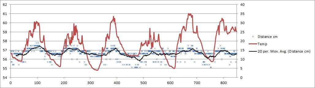
I need those temp readings to correct distance readings, daily fluctuations during fixed testing were within 2 cm. The correlation with temperature was linear enough and corrections therefore easy to implement if I have the temperature readings.
In the good side it seems to consume littebit less power than v2.3.
Attachments:
-
2016-02-27 at 6:09 PM #1384
If you are referring to internal temperature from the rtc chip, there is none on the v3; value of -127 means there is effectively no sensor.
-
2016-06-27 at 10:21 PM #1611
Hi guys. I was really impressed with your early Seeduino Stalker ultrasonic water level sensor and I have tried to build one of my own.
I was not fast enough to get hold of your Mayfly so have used a Seeduino Stalker V3 and I have been struggling to get my code to work.
I have used a maxbotix 7360 sensor and want to try to record the Serial output as I am trying to achieve 1 mm accuracy.
Any chance you could share the code you used with your Stalker versions of your project?
I’m Happy to share what I have so far but as I am not really sure whats wrong with it I don’t really know how to fix it.
It will only print one sample to the Serial output and to the SD card then goes into a coma.
Also do you think there will be another run of the mayfly anytime soon?
Any help you could give would be really appreciated. -
2016-06-28 at 12:44 PM #1614
I’m not sure why your code didn’t post correctly. Maybe because you attached it as a .ino file. Try just pasting it into the “code snippet” box when you’re typing a reply. Just hit the “Add Code Snippet” button in the row of buttons right above the text box, past your code into the window that pops up and choose “Arduino” from the Language drop-down menu so it formats the code properly.
Here’s some code that I used a long time ago when using the Maxbotix sensors with a Seeeduino Stalker. In the example, I connected the data line of the sensor to pin D7, then just connect the sensor to ground and its power to 3v3. Communicating with the Maxbotix sensor only uses pin 5, 6, and 7 on the sensor. The sensor outputs a digital string every second when it’s powered continuously. If you only want to take readings periodically, you can power the sensor momentarily with any of the free digital pins on the Stalker since the sensor only uses a few milliamps so the Arduino digital pins can source that. In the following example, it’s powered all the time.
Arduino1234567891011121314151617181920212223242526272829303132333435363738394041424344454647484950515253545556575859606162636465666768697071/* test function to Parse data from MaxSonar serial data and return integer */#include <SoftwareSerial.h>SoftwareSerial sonarSerial(7, -1); //define serial port for recieving databoolean stringComplete = false;void setup(){Serial.begin(9600); //start serial port for displaysonarSerial.begin(9600); //start serial port for maxSonardelay(100);}void loop(){int range = EZread();if(stringComplete){stringComplete = false; //reset sringComplete ready for next readingSerial.print("Range: ");Serial.println(range);Serial.println(" mm");delay(1000); //delay 1 second}}int EZread(){int result;char inData[6]; //char array to read data intoint index = 0;sonarSerial.flush(); // Clear cache ready for next readingwhile (stringComplete == false) {//Serial.print("reading "); //debug lineif (sonarSerial.available()){char rByte = sonarSerial.read(); //read serial input for "R" to mark start of dataif(rByte == 'R'){//Serial.println("rByte set");while (index < 5) //read next three character for range from sensor{if (sonarSerial.available()){inData[index] = sonarSerial.read();//Serial.println(inData[index]); //Debug lineindex++; // Increment where to write next}}inData[index] = 0x00; //add a padding byte at end for atoi() function}rByte = 0; //reset the rByte ready for next readingindex = 0; // Reset index ready for next readingstringComplete = true; // Set completion of read to trueresult = atoi(inData); // Changes string data into an integer for use}}return result;} -
2016-06-28 at 6:27 PM #1617
Hi
Thanks for the help, I really appreciate the well commented code as I really have no idea whats going on without it.
I tried your code and perhaps I was having data issues because Of something I did or because of a different sensor but I was getting quite a few out of sync readings that would throw a spanner in the works for using the data later.
I have had really good data coming from the code attached here, hopefully between the two options someone may get some benefit out of these options.Maxbotix7360 software serial mmArduino12345678910111213141516171819202122232425262728293031323334// RX, TX, true sets the invertervoid setup(){// Open serial communications and wait for port to open:Serial.begin(9600);// set the data rate for the SoftwareSerial portmySerial.begin(9600);delay(50);}void loop() {int index = 0;boolean startreading = false;char mm[6];mySerial.flush();while(index < 4){if(mySerial.available()){byte incoming = mySerial.read();if(incoming == 'R') {startreading = true;} else if(startreading) {mm[index++] = incoming;}}}Serial.print("mm: ");Serial.print(mm);Serial.print(" ");Serial.println();//delay(500);} -
2016-06-28 at 6:52 PM #1619
Ok so I have the sensor reading well with the code above and I have a sample of the seeduino datalogger that also seems to work but I cant seem to embed one code to the other and have it keep working. it just seems to put the poor little arduino into a coma after taking and writing one sample to the SD card.
Ill attach the datalogger code and hopefully some clever person out there can help.
this code works well on its own.Seeduino Stalker V3 DataloggerArduino123456789101112131415161718192021222324252627282930313233343536373839404142434445464748495051525354555657585960616263646566676869707172737475767778798081828384858687888990919293949596979899100101102103104105106107108109110111112113114115116117118119120121122123124125126127128129130131132133134135136137138139140141142143144145146147148149150151152153154155156157158159160161162163164165//Data logger Demonstration using Seeeduino Stalker v3.0. Logs Battery Voltage every 10 seconds to DATALOG.CSV file//Use this demo code to implement your Datalogger functionality, add additional sensors.//1.Solder P3 and P2 PCB jumper pads//2.Compile and upload the sketch//3.See if everything works fine using Serial Monitor.//4.Remove all Serial port code, recompile the sketch and upload.// This reduces power consumption during battery mode.#include <avr/sleep.h>#include <avr/power.h>#include <avr/power.h>#include <Wire.h>#include <DS1337.h>#include <SPI.h>#include <SD.h>//The following code is taken from sleep.h as Arduino Software v22 (avrgcc) in w32 does not have the latest sleep.h file#define sleep_bod_disable() \{ \uint8_t tempreg; \__asm__ __volatile__(“in %[tempreg], %[mcucr]” “\n\t” \“ori %[tempreg], %[bods_bodse]” “\n\t” \“out %[mcucr], %[tempreg]” “\n\t” \“andi %[tempreg], %[not_bodse]” “\n\t” \“out %[mcucr], %[tempreg]” \: [tempreg] “=&d” (tempreg) \: [mcucr] “I” _SFR_IO_ADDR(MCUCR), \[bods_bodse] “i” (_BV(BODS) | _BV(BODSE)), \[not_bodse] “i” (~_BV(BODSE))); \}DS1337 RTC; //Create RTC object for DS1337 RTCstatic uint8_t prevSecond=0;static DateTime interruptTime;static uint16_t interruptInterval = 10; //Seconds. Change this to suitable value.void setup (){/*Initialize INT0 pin for accepting interrupts */PORTD |= 0x04;DDRD &=~ 0x04;Wire.begin();Serial.begin(57600);analogReference(INTERNAL);RTC.begin();pinMode(4,OUTPUT);//SD Card power control pin. LOW = On, HIGH = OffdigitalWrite(4,LOW); //Power On SD Card.Serial.print(“Load SD card…”);// Check if SD card can be intialized.if (!SD.begin(10)) //Chipselect is on pin 10{Serial.println(“SD Card could not be intialized, or not found”);return;}Serial.println(“SD Card found and initialized.”);attachInterrupt(0, INT0_ISR, LOW); //Only LOW level interrupt can wake up from PWR_DOWNset_sleep_mode(SLEEP_MODE_PWR_DOWN);//Enable Interrupt//RTC.enableInterrupts(EveryMinute); //interrupt at EverySecond, EveryMinute, EveryHour// or thisDateTime start = RTC.now();interruptTime = DateTime(start.get() + interruptInterval); //Add interruptInterval in seconds to start time}void loop (){////////////////////// START : Application or data logging code//////////////////////////////////float voltage;int BatteryValue;BatteryValue = analogRead(A7);voltage = BatteryValue * (1.1 / 1024)* (10+2)/2; //Voltage dividerDateTime now = RTC.now(); //get the current date-timeif((now.second()) != prevSecond ){//print only when there is a changeSerial.print(now.year(), DEC);Serial.print(‘/’);Serial.print(now.month(), DEC);Serial.print(‘/’);Serial.print(now.date(), DEC);Serial.print(‘ ‘);Serial.print(now.hour(), DEC);Serial.print(‘:’);Serial.print(now.minute(), DEC);Serial.print(‘:’);Serial.print(now.second(), DEC);Serial.print(” “);Serial.print(voltage);Serial.print(” V”);Serial.println();}prevSecond = now.second();//|||||||||||||||||||Write to Disk||||||||||||||||||||||||||||||||||File logFile = SD.open(“DATALOG.CSV”, FILE_WRITE);if(logFile) {logFile.print(now.year(), DEC);logFile.print(‘/’);logFile.print(now.month(), DEC);logFile.print(‘/’);logFile.print(now.date(), DEC);logFile.print(‘,’);logFile.print(now.hour(), DEC);logFile.print(‘:’);logFile.print(now.minute(), DEC);logFile.print(‘:’);logFile.print(now.second(), DEC);logFile.print(‘,’);logFile.println(voltage);logFile.close();}//|||||||||||||||||||Write to Disk||||||||||||||||||||||||||||||||||RTC.clearINTStatus(); //This function call is a must to bring /INT pin HIGH after an interrupt.RTC.enableInterrupts(interruptTime.hour(),interruptTime.minute(),interruptTime.second()); // set the interrupt at (h,m,s)attachInterrupt(0, INT0_ISR, LOW); //Enable INT0 interrupt (as ISR disables interrupt). This strategy is required to handle LEVEL triggered interrupt////////////////////////END : Application code //////////////////////////////////\/\/\/\/\/\/\/\/\/\/\/\/Sleep Mode and Power Down routines\/\/\/\/\/\/\/\/\/\/\/\/\/\/\/\//Power Down routinescli();sleep_enable(); // Set sleep enable bitsleep_bod_disable(); // Disable brown out detection during sleep. Saves more powersei();digitalWrite(4,HIGH); //Power Off SD Card.Serial.println(“\nSleeping”);delay(10); //This delay is required to allow print to complete//Shut down all peripherals like ADC before sleep. Refer Atmega328 manualpower_all_disable(); //This shuts down ADC, TWI, SPI, Timers and USARTsleep_cpu(); // Sleep the CPU as per the mode set earlier(power down)sleep_disable(); // Wakes up sleep and clears enable bit. Before this ISR would have executedpower_all_enable(); //This shuts enables ADC, TWI, SPI, Timers and USARTdelay(10); //This delay is required to allow CPU to stabilizeSerial.println(“Awake from sleep”);digitalWrite(4,LOW); //Power On SD Card.//\/\/\/\/\/\/\/\/\/\/\/\/Sleep Mode and Power Saver routines\/\/\/\/\/\/\/\/\/\/\/\/\/\/\/\}//Interrupt service routine for external interrupt on INT0 pin conntected to DS1337 /INTvoid INT0_ISR(){//Keep this as short as possible. Possibly avoid using function callsdetachInterrupt(0);interruptTime = DateTime(interruptTime.get() + interruptInterval); //decide the time for next interrupt, configure next interrupt}-
2016-06-29 at 5:30 PM #1624
Did you put a solder blob across the pads of P3 on the back of the board? You’re using INT0 in the code, so you need to close the pads that connect the RTC interrupt signal to pin D2, and according to the Stalker 3.0 wiki, that is accomplished by shorting out P3. I have not used a Stalker 3.0, but I know on the Stalker 2.3, the board would go to sleep after one reading and never wake up again if I forgot to short that RTC INT0-D2 solder jumper.
-
-
2016-06-29 at 7:54 PM #1626
Hi
I have just double checked the jumpers I soldered across P2 and P3 as you say to make sure it was not some sort of dry joint problem and all seems well.
The problem I am having it seems is that the software serial is not playing ball after the first sleep, wake up cycle. I have just tried the re allocating sonar onto pin 8 instead of pin 11 and got totally different behavior so will try some more things and give an update. All of the info I can find pointed to pin 11 being free as was pin 8 so I wonder if I am Missing something. -
2016-06-29 at 8:14 PM #1627
Pins 10, 11, 12, and 13 on the Stalker are used by the SPIbus, so if you’re want to use the microSD card socket, you can’t use those digital pins for anything else. It’s been awhile since I looked at the specs of the Stalker, but I think there are very few free pins. That’s one of the reasons we stopped using it and created the Mayfly. And the Mayfly’s secondary hardware serial port makes it easier since you can sometime avoid using the SoftwareSerial functions if you just have one serial device to interface with.
The Mayfly boards should be available again on Amazon by this weekend.
-
2016-06-29 at 8:32 PM #1628
Awesome, I will be one of the first to buy one once they are back in stock.
The 10 11 pin issue is what seems to have made things screwy all along, Now to go find some free pins, using pin 8 seems to make it cycle through the sleep awake about 4 times before getting another sample. It may still be broken but at least it’s different broken 😉 -
2020-08-05 at 10:19 AM #14449
Hello,
I’m sorry to dig up this old post but it seems the right place to post. Tell me if it’s better to create a new post.
So here’s my problem :I plugged the MB7363 Sonar sensor from Maxbotix to the Seeeduino Stalker v3.1 . I used the analog pin of the sonar (pin 3) and I connected it to the analog A1 input of the Seeeduino Stalker, Vpin to the 3,3v and GndPin to the GND pin, as you can see in the following picture :
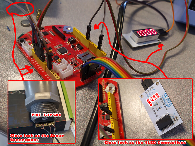
I also added a 4LED display to show the value of the sonar from the analog input, again, as shown on the picture.
Everything work fine this way, but when I want to remove the LED display, the value of the analog input coming from the sonar drops to 0. If I reconnect the LED display, correct value from the sonar start being read again. Thing is that I use the LED display as debug and I need to remove it at the end to put this setting (Seeeduino Stalker connected to a battery) in a closed box. Leaving the LED display will use too much power.
So, is there anyone here that have any idea about what is going on here and how can I make it work without the LED display ?
Why is my readings on 0 when I have only my Maxbotix Sonar connected ? I tested the same code with the same setup on Arduino Mega and it works fine (with or without the 4LED display)..Here’s the code I used :
Arduino12345678910111213141516171819202122232425262728293031323334353637// include 4LED library /////////////#include <TM1637Display.h>// Variables 4LED //////////////////////////////////////////////const int CLK = 3; //Set the CLK pin connection to the displayconst int DIO = 9; //Set the DIO pin connection to the displayTM1637Display display(CLK, DIO); //set up the 4-Digit Display.//////////////////////////////////////////////////////////////////Set the Maxbotix pin to receive the signal.const int anPin = 1;long pulse;void setup(){/// 4LED Setup //////////////////////////////////////////////////////display.setBrightness(0x0a); //set the diplay to maximum brightness//Open up a serial connectionSerial.begin(9600);}//Main loop where the action takes placevoid loop(){pulse = analogRead(anPin);Serial.print("The value is: ");Serial.print(pulse);display.showNumberDec(pulse);Serial.println();delay(500);//////////////////////////////////////////////////////////////////////} -
2020-08-07 at 11:31 AM #14461
Not sure why it’s not working based on what’s visible in the sketch you posted. But I’m guessing there’s something happening in the TM1637Display library that is looking for return data or confirmation from the display in order for the sketch to continue, so without the display plugged into your Stalker, the sketch hangs and stops, rather than ignoring the lost display and moving on.
I’d recommend something like this display: https://shop.switchdoc.com/products/grove-128×64-i2c-oled-board-for-arduino-and-raspberry-pi
It uses much lower power, you can remove it at any time from the board while the sketch is running and it won’t interrupt things. It has a Grove jack on it, so you can just connect it to one of the Grove ports on your Stalker (or our Mayfly) with a basic Grove cable (they come in various lengths).
-
2020-08-12 at 7:48 AM #14467
Thanks for taking the time to answer me.
I did some others tests, and this became much weirder. So, I removed all the code about the LED display, and still not working (value stay on 0). So I tried connecting the LED display to see how it react, despite the fact there was no code about it. When I plugged the power and ground wire on their respective pin on the Stalker, and one of the two (CLK or DIO, doesn’t matter which) on DIGITAL PIN 9, sonar reads corrects values again… The 4LED does not show any value (of course, no code was written about, and wires are not all connected), but the sonar works..
So I tried something else. I removed the 4LED module, and wired the 5vcc Stalker pin directly to the DIGITALPIN 9. Sonar works and read correct value. Thing is, I don’t know why it works that way. I tried on other digital pins, and it doesn’t work. It’s only on digital pin 9. Is it possible that some trash code is left somewhere on the Stalker and it somehow wait to get signal on DPin 9, or do I have a Stalker that is messed up ?
-
-
AuthorPosts

- You must be logged in to reply to this topic.