
Home › Forums › Environmental Sensors › Connecting apogee pyrgeometer and two apogee pyranometers to the Mayfly
Tagged: ADC, apogee, excitation, power supply, SL-510-SS, SP-510-SS, SP-610-SS, wiring
- This topic has 0 replies, 1 voice, and was last updated 2023-05-10 at 1:16 PM by
 Braedon.
-
AuthorPosts
-
-
2023-05-10 at 1:16 PM #17805
I am looking to connect an apogee SL-510-SS pyrgeometer to the Mayfly board. Eventually, I hope to have two apogee pyranometers on the same board as well, the SP-510-SS and the SP-610-SS. Because there are only four ADC pins (as far as I understand how the board works) it looks like I have to take single-ended measurements instead of differential measurements from the sensors to free up pins. Apogee has a small article discussing taking single-ended measurements from differential sensors by connecting your low wire to ground instead of another analog pin:
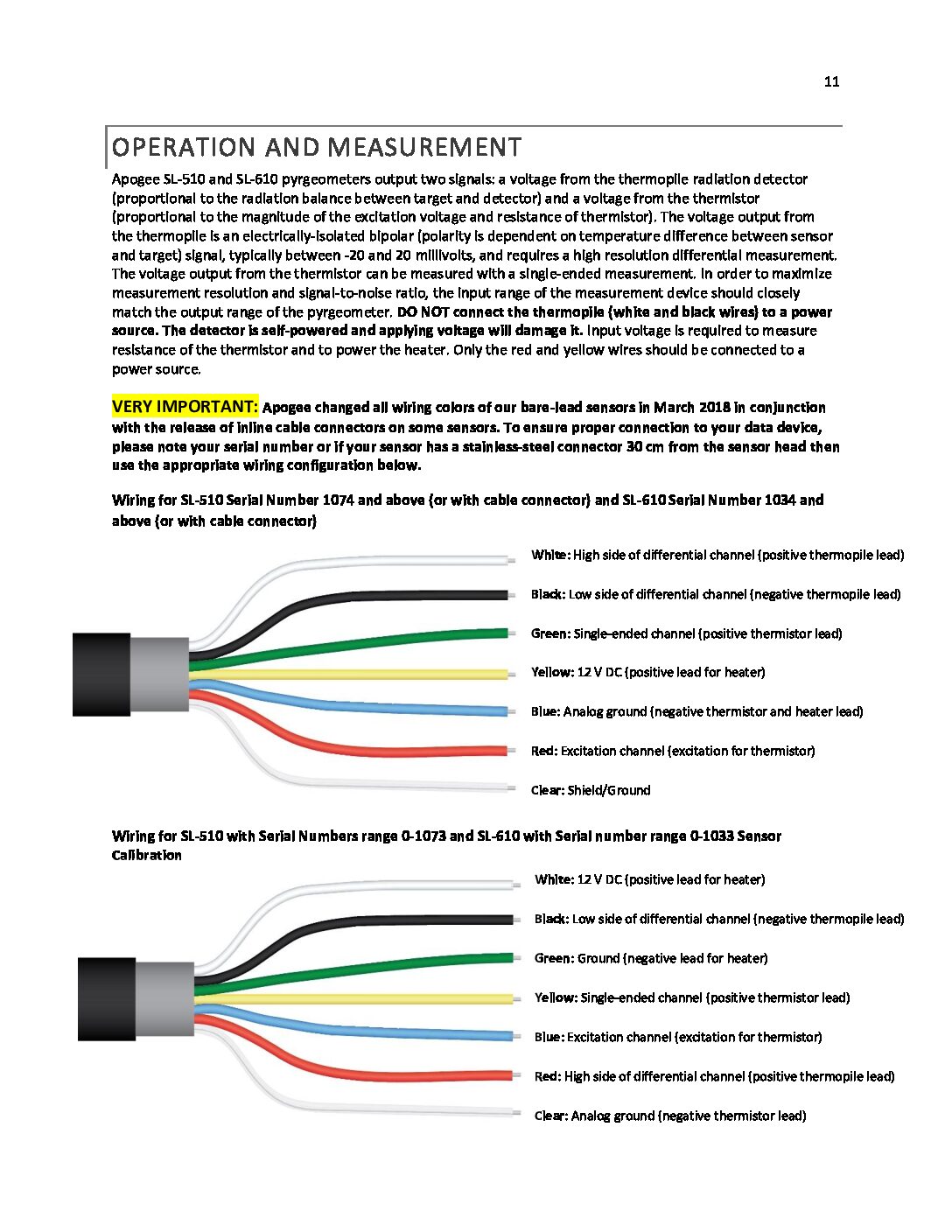
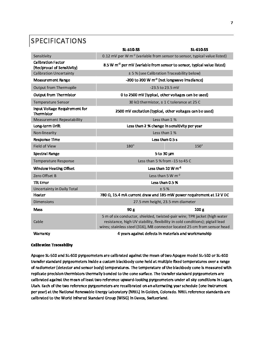
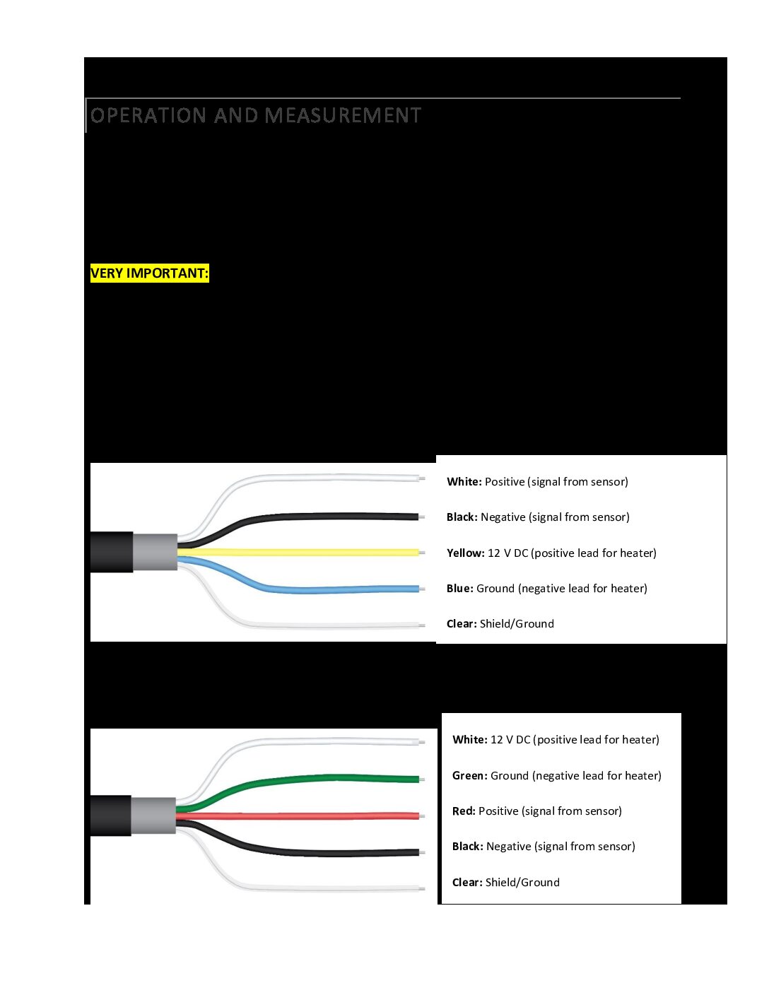
The two pyranometers together would take up two pins and the pyrgeometer would take up two pins, with one pin giving the thermopile output voltage and one pin giving the thermistor output voltage (both are needed for calculating the longwave radiation). My hope is that I can get these three sensors working on the same board. I am not sure how to wire this, and I have a couple of questions that maybe when they’re answered will tell me how feasible this is. I have attached the specifications sheets and the wiring labels from the product manuals for both sensors in this post.
- Can multiple sensors be connected to the same power pin and ground pin? For example, could I plug in two pyranometers into the AA2 and AA3 pins and have them share that same grove terminal’s voltage supply and ground? The two pyranometers require 12 VDC to power the internal heater. Would I also run into problems with grounding the low wire for the analog reading and grounding the internal heater?
- What is an excitation voltage, which is needed for the thermistor in the pyrgeometer, and how do you supply that separately from the 12 volts of direct current needed for the internal heater of the pyrgeometer? The specifications sheet says that the thermistor needs 2500 mV of excitation, but that other voltages can be used. Do I need to connect my thermistor and internal heater to a different power supply, or can they be connected to the same source, like in my first question? If they need to be attached to different power supplies, where would be the best place to attach the thermistor power supply wire since I will have the jumper on the 12 volt switched power?
Hopefully these questions make sense. Let me know if I need to clear up anything. Any help is appreciated. Thanks!
-
-
AuthorPosts

- You must be logged in to reply to this topic.