
We are excited to announce the release of the newest version of the EnviroDIY Mayfly Data Logger and several new accessories:
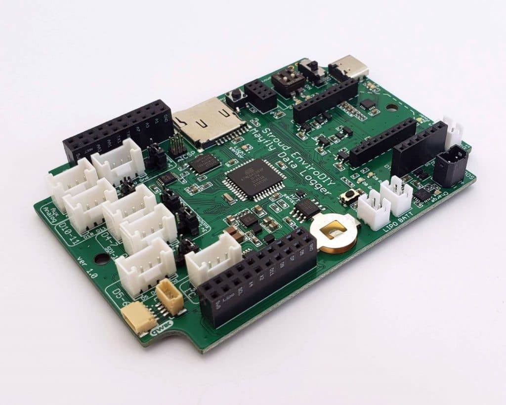
The new logger board is called Mayfly version 1.0, because it’s the first major revision to the design since the beta version 0.5 that was first released in 2016. There are also several changes to the board that make it not backwards-compatible with older hardware. The exciting thing is that several new features have been added, and the many of the existing features were improved. Some of the highlights are:
- USB-C port, faster battery charging, upgraded solar charger
- Separate voltage regulators for bee socket and switched power output (1-amp each)
- New 12-volt switched power output (or changeable to 9v)
- LEDs to show board power and USB power status
- LEDs to show bee power and network status (for supported modules)
- LEDs to show USB upload/download status during programming
- Onboard sensors: analog light sensor and digital humidity/temperature sensor
- Two Qwiic ports
- Built-in auxiliary 8MB flash memory
More details about the new Mayfly v1.0 board can be found on the Mayfly Hardware page.
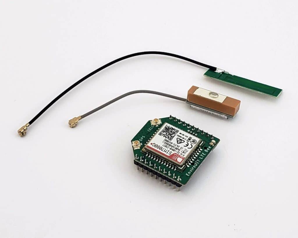
We also have a new custom EnviroDIY LTE Bee module, which utilizes the SIM7080 chip for LTE cellular with any carrier, and also has GNSS/GPS for location tracking. We’ve been testing them for several months and have had great success with them. They use much less power than any other cellular board we’ve tried, plus they plug directly in to the Mayfly board (any version) without the need for an adapter like we previously used with the Digi Xbee LTE boards. We’ll release more information about the new LTE board next week, along with sample sketches.
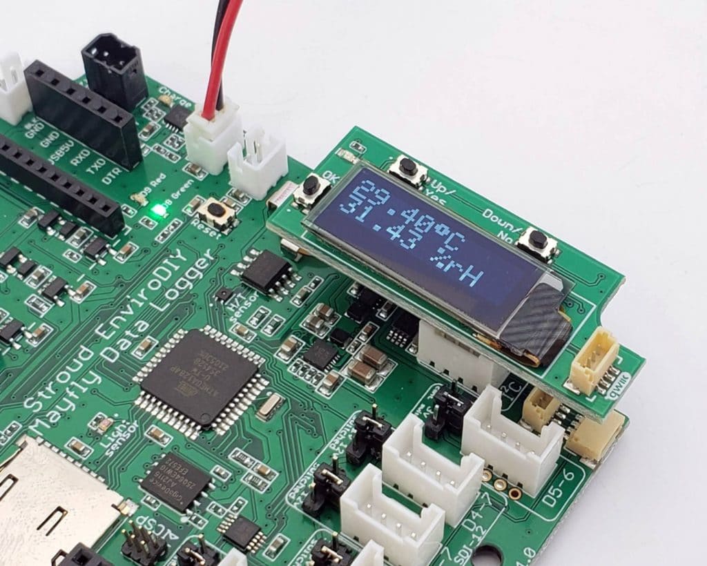
There’s also a new OLED display half-shield that you can use for displaying things like sensor readings or battery status, or use the 3 small push-buttons to interact with your Mayfly board. The display can even be put into sleep mode when the logger is asleep, so it will use no additional power. More information and sample sketches will be available soon. (note: this board only works with the new Mayfly v1.0 board and not with previous Mayfly versions)
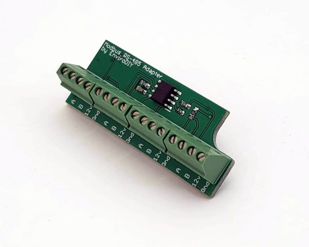
We also have a new sensor interface board: the Modbus RS-485 Adapter half-shield. It can be used with up to 4 sensors that need 12-volt power and utilize RS-485 protocol for communications. It has been successfully tested with various sensors including ones with motorized wipers. More information and sample sketches will be published very soon. (note: this board only works with the new Mayfly v1.0 board and not with previous Mayfly versions)
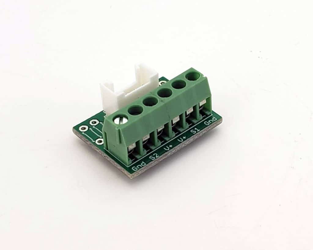
And there’s a new version of our 6-pin screw terminal board, now with easier-to-use larger size screws. We also changed the pin layout and added some extra features like holes for mounting resistors (for creating an analog voltage resistor-divider), and solder jumpers on the bottom for selecting those resistors, or for combining the two separate signal wires into one single pin on the Grove jack. Instructions on that will be posted next week. So because this board can do 3 different types of operation, we’re calling it the Multipurpose 6-pin Screw Terminal Grove Adapter. It is compatible with any Mayfly version.
All of these new products are in-stock and are being prepped for sale in our EnviroDIY Shop and on Amazon, and this page will be updated when they are available at each location, as well as an update post on the forum. There’s so much to say about each of these products and the development that went into each one that I could write a blog post about each one in the coming weeks, along with all of the regular documentation on this site and on GitHub.
neilh20
Wow fantastic to see!!. Thankyou thankyou for putting the schematic out to be able to dig into it. Great to have the LTE directly mountable on the main board and the power switchable!. Really nice to see the redesigned power system – so vital to a reliable board and real world interfaces ~ +12V boost, and also solar input with an unique socket so can’t be plugged into the wrong one, and faster hardier bq24074 LiIon charger.
I wonder what is being thought of for the new flash disk. 🙂
Hopefully will also get characterization data, my wish list is for the a) +12V booster power spec, nice to see its short circuit protected and b) the range Vbat measurement is linear over. (LiIon are rated from 4.2to 3.0V)
Can’t wait to get one 🙂
mbullard
Great work! Cannot wait to get some of the wipered turbidity sensors in the field.
Shannon Hicks
Just a little FYI, but the wiper on the Yosemitech Y511A sometimes causes issues if you’re powering the sensor directly from the Mayfly 1.0 revA3 (current release) onboard 12v boost regulator. I’ve come up with a workaround, but will have to apply it to the next manufacturing run of boards, and also make a couple minor changes to the Modbus adapter half-shield design
mbullard
OK. There was something on another thread about adding a capacitor to handle the inrush on the motor. Would this be the workaround?
Shannon Hicks
Nope, it’s a different issue related to the current-limiting circuitry in another part of the board, so a cap won’t help.
neilh20
@shicks – I wonder could you provide a technical list of target/designed functional specs and what is tested and what hasn’t. Its pretty standard to be transparent for a new product, and to list the issues (sometimes a bug?) against the revision.
What’s really hard is not knowing if something is supposed to be working, and testing it only to then find its “known broken”.
Looking at your comment, as an EE, there is “current-limiting circuitry in another part of the board” doesn’t make a lot of sense to me. Its either generating +12V with an available power rating, or its not generating any 12V. My method of testing – if its generating any 12V, is to put a large power resistor on the 12V with a series amp meter, and scope, and wind down the resistance looking for when the 12V droops and or oscillations start up. The chip also says its short circuit protected. So either Mayfly 1.0 A3 supports this to a given power OR you need to indicate that its broken for A3.
neilh20
Just wondering, will you be putting out the BOM with parts number?, in a location like https://github.com/EnviroDIY/EnviroDIY_Mayfly_Logger/tree/master/hardware. While I appreciate the overview on the new Mayfly, there is only so much that one person can respond to when it comes to detail.
For instance would be nice to know what the voltage rating are on C33, C2, D1 and D2.? bq24074 OVP is rated up to 28V.
Shannon Hicks
We’ll eventually publish the BOM when I get a chance. I’ve been doing sensor station maintenance and installation most of my time for the past couple weeks, along with getting all the products to Amazon and ready for the shop inventory (where they are now available). In the meantime I can email your the specs on the parts.
neilh20
thanks – neilh01@wllw.net. Great to see them on Amazon. Congrats a big milestone I’m sure.
I was discussing it with a Sonoma State Uni project, and they searched amazon found them and ordered the new boards. They have a timeline for a prototype and then a project for the Sonoma Center for Environmental Enquiry Fairfield Osborne Preserve.
neilh20
A colleague (EE) at Sonoma State Ca just announced they received their new Mayfly 1.0 downloaded the Arduinio IDE – from scratch and got it reporting temperature!!!! Excellent for out the box ease!!
neilh20
Hey @ Shannon, thanks for posting the Eagle files, and I was able to convert them to Ki-CAD to be able to follow the circuits/pcb . Really appreciate there is a lot of effort gone into Mayfly rev1a3, and some risk with new circuits. Really challenging with such small components.
I’ve received three rev1A3’s so looking forward to trying them out, but I would like to know where the current states goes from “cutting edge” to “bleeding edge”.
You’ve hinted that the +12V isn’t meeting design spec, but it is possible to simply measure and specify this. I created a tracking item with my cct analysis ..https://github.com/EnviroDIY/EnviroDIY_Mayfly_Logger/issues/33
When I’ve asked technical questions in the past, I haven’t got an acknowledgement that there may be something tricky, so I’m humbly checking in and trying to be helpful.
From a paper analysis I’m concerned with is the powering of the Xbee socket. For the Mayfly 0.5 it required a separate LTE board to provide sufficient power to have it run, and very obvious that it needed specific LTE powering.
I’m wondering how much testing has been performed with an LTE device (eg Digi LTE Xbee3 CAT-M1) .. and that maybe none at this stage due to software support/complexities.
I’ve put up a Norton Current analysis of the LTE powering on https://github.com/EnviroDIY/EnviroDIY_Mayfly_Logger/issues/31
For me engineering is about being reliable – a vehicle that some times doesn’t start when the temperature drops below 10C, doesn’t give me much confidence. If I’m in a cold climate I need to how cold it can get and the vehicle will be guaranteed to start – eg -10C.
Since you are talking about a new revision, one of these reliability areas is on measuring LiIon battery power from a discharged battery that is charging. It could do with some discussion how to solve it, and maybe there is a simple solution. Not sure where the discussion could be, so created issue https://github.com/EnviroDIY/EnviroDIY_Mayfly_Logger/issues/32