
A few weeks ago we released the latest hardware version of the Mayfly board, version v0.5. Here are the all of the new features that were added to the board for this release:
The board now accepts an external voltage of 4 to 12 volts. The previous board versions couldn’t accept anything higher than 6v on the external power input without causing some overheating on a regulator and some power draw issues during sleeping. There is a small switch next to the external power input pins that lets the user choose whether the board is powered via the regular method (USB or Lipo battery), or through the external input pins. You’ll probably want to install a handy polarized header jack like the one shown in the photo below for connecting the Mayfly to your external source.
Note: To prevent over-voltage damage, the USB port is disconnected from the Mayfly when the switch is set to “Ext”. If you are using the Mayfly with an external battery and then want to reprogram the Mayfly, you’ll need to slide the switch to “USB/Lipo” in order to program the board. Then slide it back to “Ext” to power the board via your external source. If you have a Lipo battery connected to the “Lipo Batt” JST headers, be sure to keep the slide switch in the “USB/Lipo” position or the board will not be powered.
The switched 3.3v and 5v power rails that are accessed through the Grove terminals or the Sw3 or Sw5 pins are now powered by their own independent regulator, which has a maximum current of 500ma. On previous versions, the switched power came from the same regulator that powered the rest of the board, including the processor, so sometimes switching a noisy or heavy load caused glitches which made the processor reboot. This new method gives the user the ability power heavier loads (up to 500ma) without interfering with the power on the rest of the board.
The 5v boost regulator was replaced with a new and better one. The old boost regulator (NCP1402) had a maximum source current of 200ma, but the new one (SC4503) will source up to 500ma because it’s powered by the separate regulator as mentioned above.
An onboard 1M-ohm resistor has been added to the board for pulling up digital pin D10 to 3.3v for applications where you want to use D10 as a hardware interrupt (D10 is one of the 3 hardware interrupt pins on the Mayfly, in addition to D2 and D3, which are usually used for the Xbee coms). The default position is OFF. Add a solder bridge to SJ12 if you want to connect D10 to the onboard pullup resistor. DO NOT use this jumper if you have modified SJ1 to use D10 as the RTC interrupt. Also, DO NOT use this jumper if you are using D10 for any other type of input besides something that needs the pullup. For more information about the solder jumpers, be sure to read this page: https://envirodiy.org/mayfly/hardware/jumper-settings/
And the printed labels next to the Grove I2C port are now correct. The SCL and SDA labels were printed backwards on the previous board version. The wiring of the board was correct on the earlier boards, only the white printed labels were swapped.
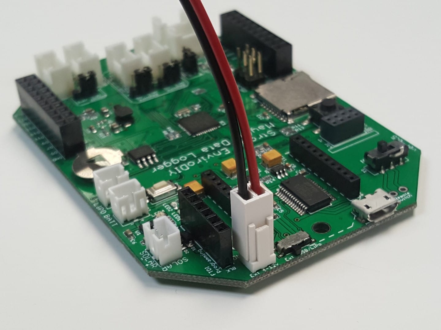
Example of how to connect external 4-12v to the Mayfly