
This post was written by @ehost11 and @crpelissero as part of their senior capstone project at University of St. Thomas in St. Paul, Minnesota. The capstone course was co-taught by @tahicksonstthomas-edu and @fisherba.
Monitoring groundwater can be expensive and time consuming, so our goal was to supply Comfort Lake Forest Lake Watershed District (CLFLWD) in Forest Lake, Minnesota with an easy to use, low cost, and low power system that continuously monitors groundwater levels with minimal visits to the site, a restored wetland, called Bixby Park, outlined in red in the image below. The CLFLWD will be able to better understand the relationships between the groundwater level in the wetland and precipitation events that serves as the main recharge source for the wetland with the conclusion of this project. Here we provide future users with the following step-by-step guide for building, programming, and troubleshooting the low cost continuous groundwater level system and software.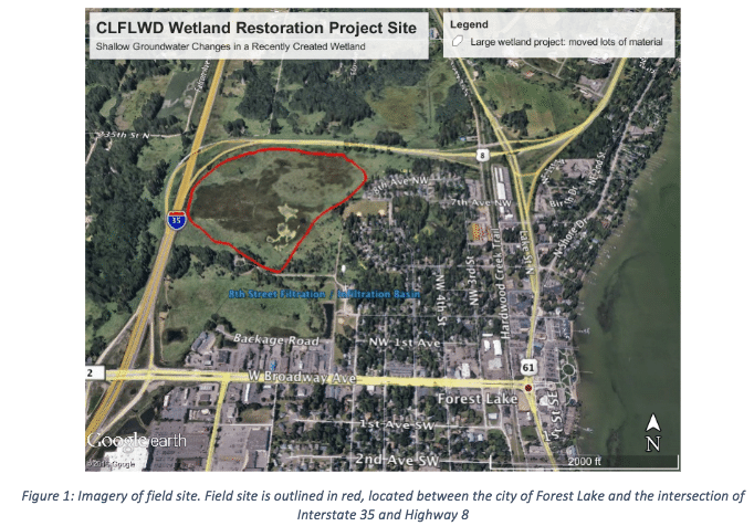
Data logger and sensor assembly
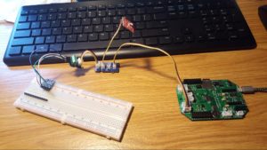
We developed a monitoring system using off-the-shelf components, and this tutorial will demonstrate how we soldered the electronic components for communication with an Arduino-based data logger, enclosed electronics in epoxy for waterproofing, devised a protective enclosure for the sensors, and encased all of the electronics in a waterproof box for continuous use outdoors. For a cost comparison, our complete monitoring system costs about $370, whereas most commercial dataloggers range from $500-$2000.
We used an Arduino-based EnviroDIY Mayfly data logger board (all parts are linked in Table 1, at end of post). 
We used the following sensors:
- MS5803-14BA pressure sensor breakout board, used for water pressure,
- BME280 atmospheric sensor breakout board used to correct for the influence of barometric pressure on the water pressure, and
- DS18B20 waterproof digital temperature sensor (we have a tabulated parts list with links at the end of this blog post, Table 1).
The BME280 and MS5803 sensors use the I2C communication protocol, and the Mayfly has a built in Grove port for I2C. We used a generic digital ports for the DS18B20 temperature sensor. The pin header rails on the sides of the Mayfly allow for other connection approaches to the same pins.
We calculated the water level by determining the hydraulic head, which involves measuring the water pressure and subtracting the air pressure. The EnviroDIY ecosystem has a Modular Sensors sketch (or program) for the air pressure correction and logging, which you can now find in two tutorials. The Learn EnviroDIY programming tutorial uses a code editor to manage your Arduino libraries, or the EnviroDIY Monitoring Station Manual directs you to use Arduino IDE with Modular Sensors sketches (you will need to more manually manage libraries).
Below are the steps we followed to assemble the sensors and electronics.
Steps to build the sensor and deployment package
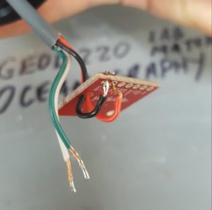
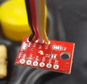
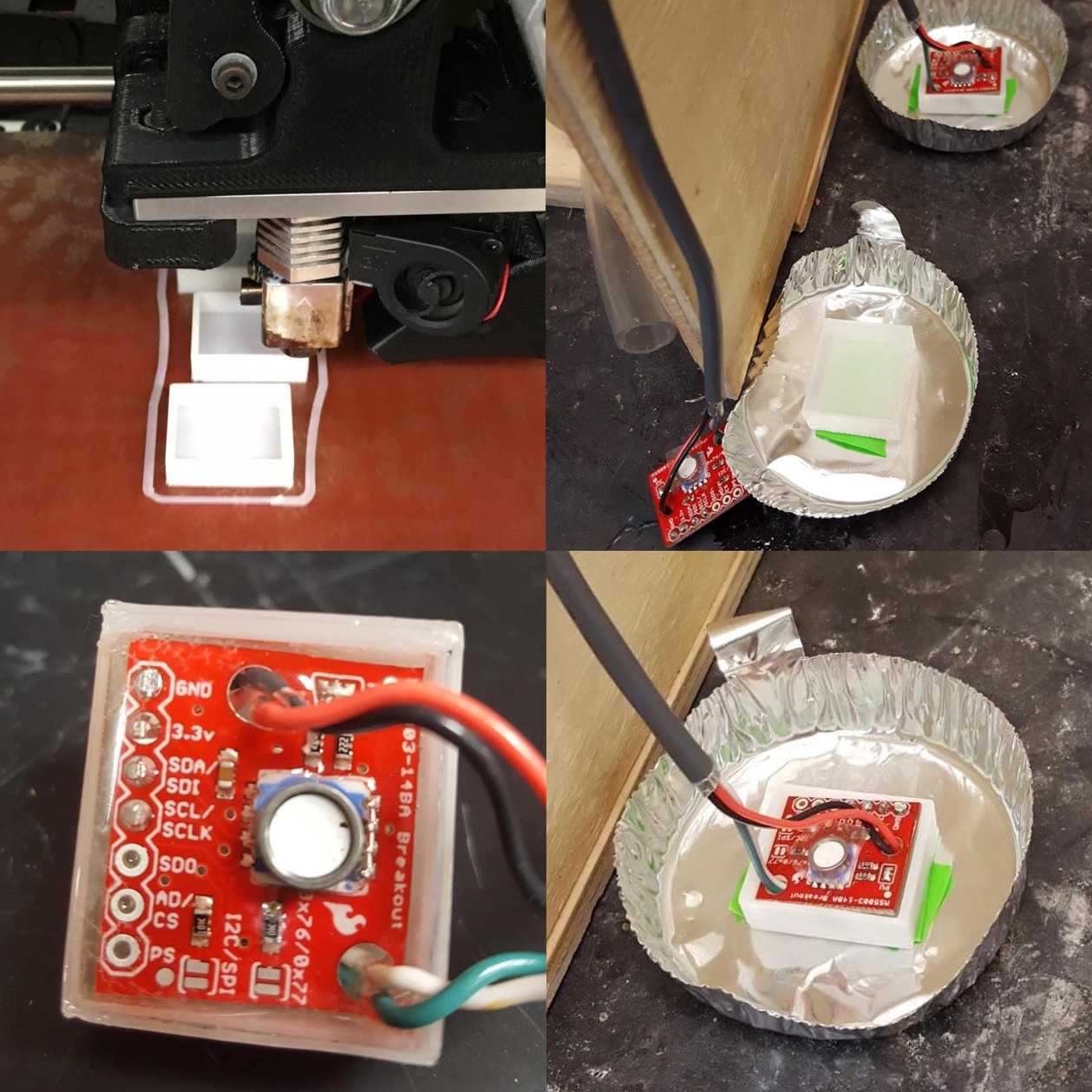
- In order for the water pressure sensor to be submerged under water, we needed the electronics to be protected from water but allow the sensor itself to be exposed to the water that it is measuring. We passed the wires through holes present in the top of the board and soldered them directly to the terminals at the bottom of the board to keep the top of the board low-profile for epoxy application. NOTE: The example below was a prototype of the soldering and wiring method and an example of how your final product should not look! Instead, the plastic coating around the wires should be pushed close to the board and excess wire should be trimmed off (like the photo below for the BME280).
- We used a 3D printer to print dish-shaped molds to encase the sensors in the epoxy. We placed epoxy into the mold to cover the bottom, then we placed the sensor in, and applied more epoxy to the top of the board. It is extremely important to make sure that epoxy covers all of the electronics very well; even a small amount of contact with water would render the sensor useless.

- We placed a small piece of tape over the gel membrane to protect the sensor diaphragm from drips of epoxy during application. We used Buehler EpoThin 2 Resin and Hardener, (which is intended for applications like embedding sediments for microscopic analyses, so it’s probably not a first choice for epoxy, but it’s what we had in the lab. We know others who use Scotch-Weld EC2216). We taped the plastic molds and catch trays to the table to keep the molds stationary while the epoxy was setting.
BIG NOTE: Water-sealing this sensor was the most finicky part of the process, and we lost several sensors because something went wrong in the process, and often we had trouble detecting what went wrong. Here are some speculations about what might have gone wrong:- Often resins bond poorly (they are meant to fully surround the object, not stick to it), and the metal rind on the pressure sensor is make of surgical steel, so made to not have stuff stick to it and be super smooth.
- EpoThin a really specialized resin intended to optimize optically clarity to encapsulate stuff for microscopic analysis, and sometimes with this specialization there are sacrifices and such products should be approached with scrutiny.
- For our next batch of pressure transducers we purchased pre-sealed and tested sensors from our open-source friends at Northern Widget. Their products are not as “easy” to purchase as the things from Amazon (you have to email them), but they are super kind folks who are responsive and make some great sensors and loggers. http://www.northernwidget.com/sensors/2018/06/13/tp-downhole.html
- Because water pressure is influenced by atmospheric pressure, we need to subtract air pressure from the water pressure to calculate water level. We used the BME280 atmospheric sensor breakout board from SparkFun, which measures barometric pressure, temperature, and humidity, and we connected it to the I2C hub. We housed it inside the Pelican case (which is vented) so we did not need to weather proof it. This means that temperature and humidity measurements from this sensor tell us more about these properties inside the Pelican case, but we believe the vent allows us to get reasonable atmospheric pressure.
- We planned to use the DS18B20 waterproof digital temperature sensor from Adafruit to correct for the influence of temperature on the pressure of the water, but calculated that it does not have a large influence in groundwater. The 4.7K ohm pull-up resistor was soldered onto the back of a screw terminal to keep the wires waterproof and the connection more secure. This sensor communicates through 1-Wire communication protocol, so we connected it to the D4-D5 digital grove port.
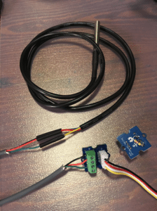
- We soldered the sensor to a 3 meter cable based on the depths of our piezometers. Note: the I2C communication protocol is limited to cable lengths of around 10 meters. We would need a different communication protocol if we wanted to deploy our sensors in deeper wells.
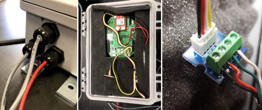
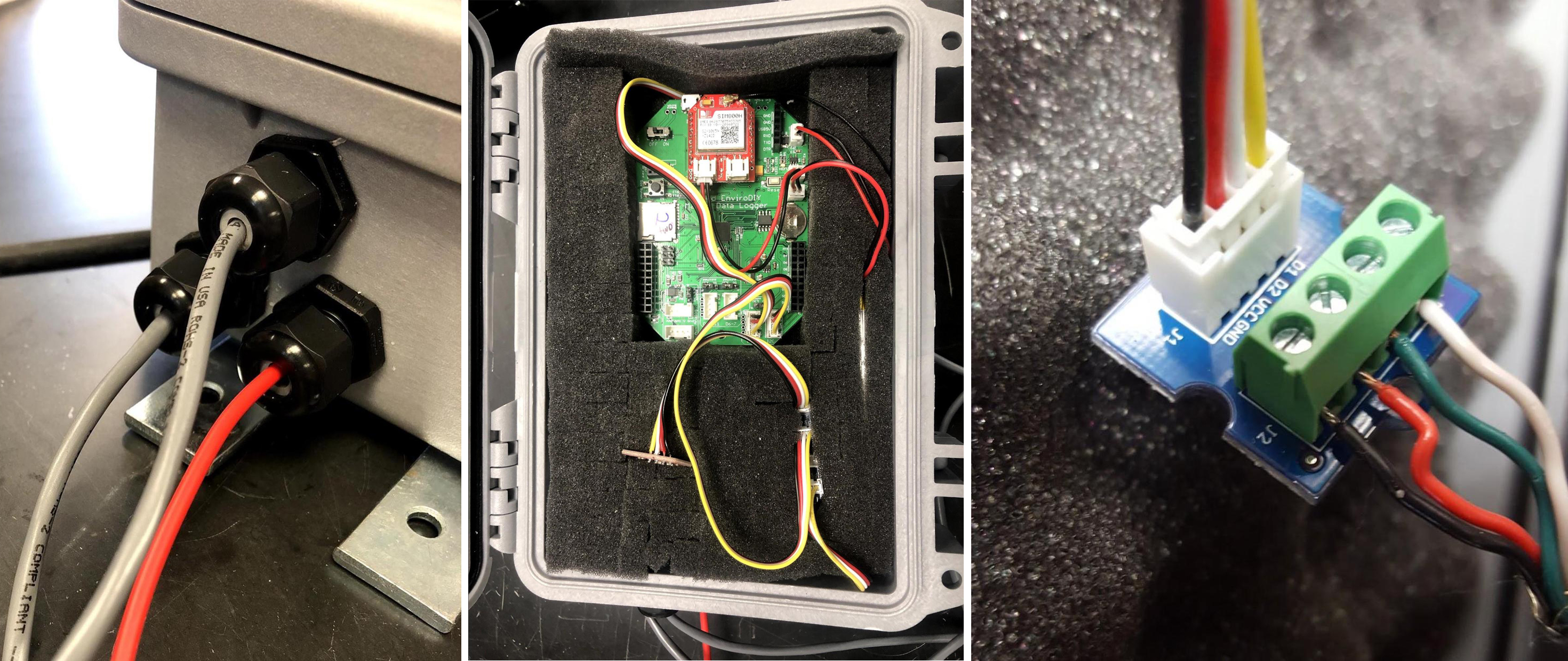
- We fed the cables into a Pelican case through a watertight cord grip (instructions below). In order to have a watertight enclosure, you will need to leave the non-sensor end of your cable with bare wires. We recommend that you “tin” the bare wires by adding a thin coat of solder, to prevent fraying and to allow them to securely connect to your logger board via a screw terminal.
- To utilize the Grove ports on the Mayfly, we connected our bare wire sensors to screw terminals and used and I2C hub to connect multiple sensors into one port. (We did not use a breadboard inside for our final deployment!)
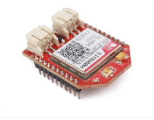
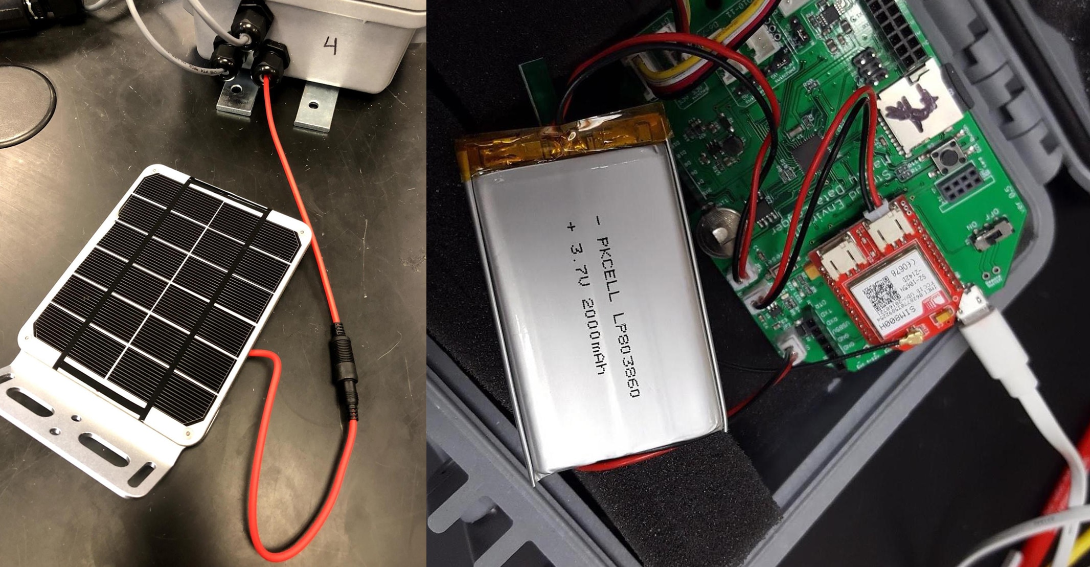
- Logging: The Mayfly datalogger has the capability to log to an onboard MicroSD card. We also logged to the internet over the cellular network using a GPRSbee rev.7 (2G) and a Hologram SIM and logged to data.EnviroDIY.org.
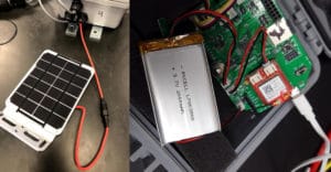
- To power the data logger, we used a 6V 2W solar panel (Voltaic) and a rechargeable Lithium ion 3.7v 2000mAh battery (Table 1). Make sure your battery solar panels are sized appropriately for the power draw for your sensor setup.
- The sketch we used was adapted from the EnviroDIY Modular Sensor library, available on GitHub (https://github.com/EnviroDIY/ModularSensors). Our project lead to the development of the example sketch called baro_rho_correction.ino, which was the first sketch in the Modular library to allows for a calculated variable using values from two different sensors. The sketch includes the standard correction for barometric pressure (“baro”) and the option to correct for water density (“rho”). A tutorial post detailing how to use the Modular Sensor library can will be posted soon.


Monitoring station assembly
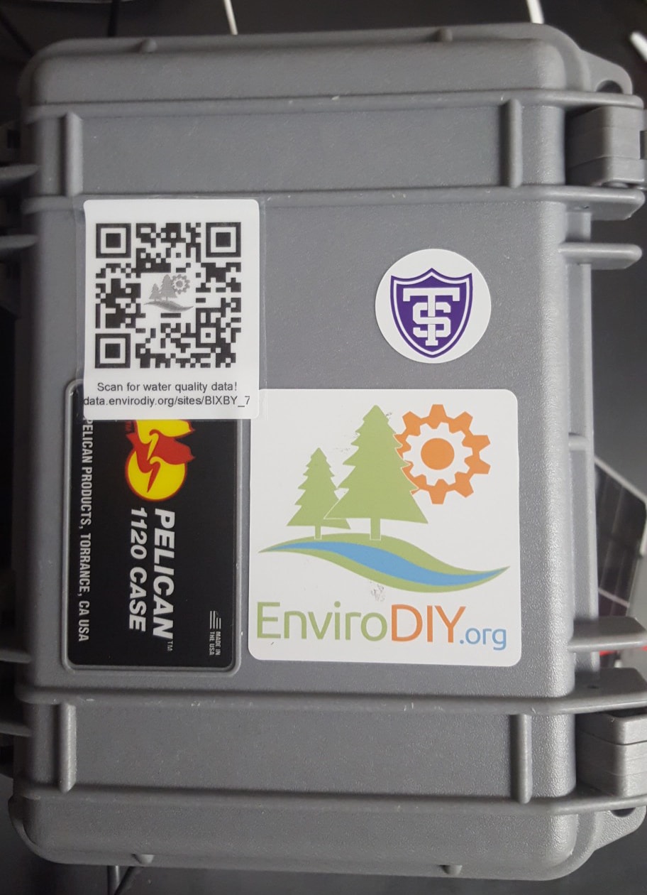
To allow the data logger to be installed outside, the electronics needed to be placed into a waterproof case; we used the Pelican 1120 case. Below are the steps we followed to construct the monitoring station.
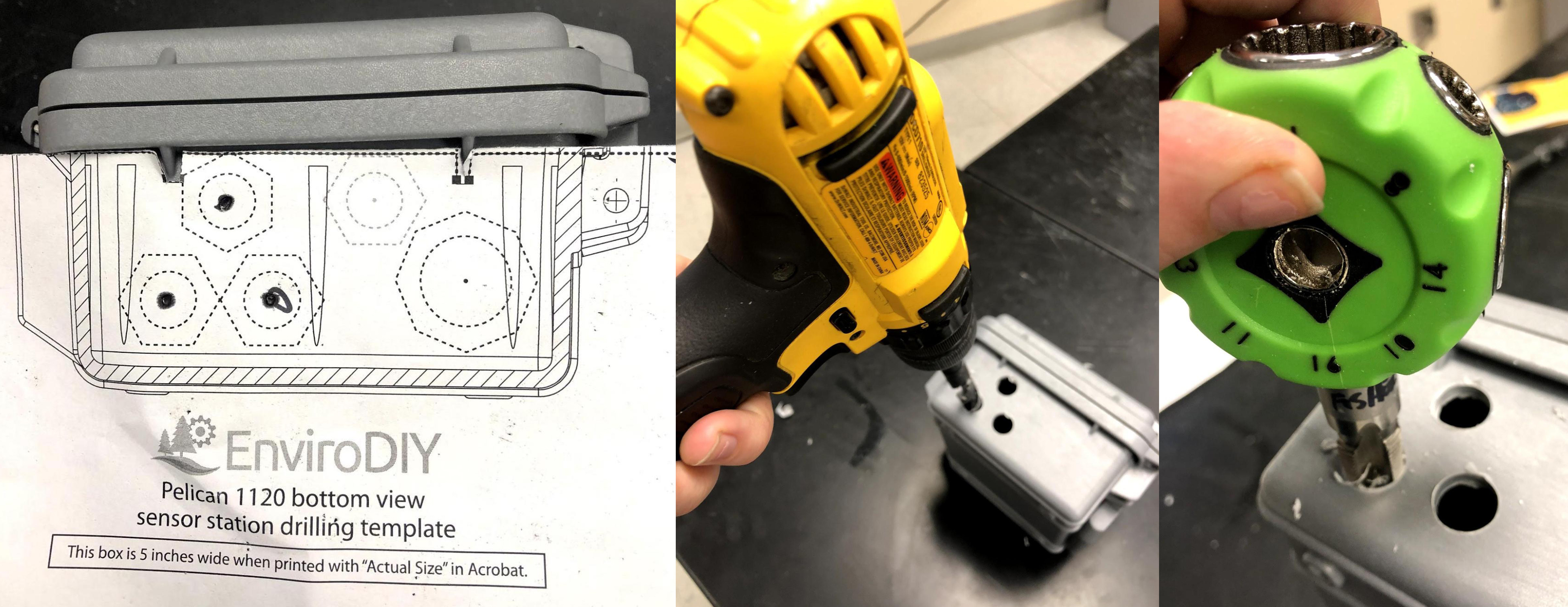
- We drilled holes into the side of the Pelican case using the box template, where the EnviroDIY community has optimized the number of cord grips you can fit onto the Pelican 1120 case. The corresponding drill and tap sizes for each cord grip size are indicated on the drilling template.
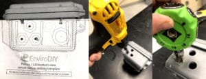
- We drilled three ⅜” holes and tapped them with a ⅜” screw tap, as defined by the submersible cord grips we selected.
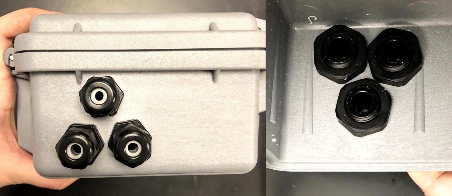
- We installed ⅜” “Compact Plastic Submersible Cordgrips” into the holes. Note: these come in several sizes to accommodate the diameter of your cords.

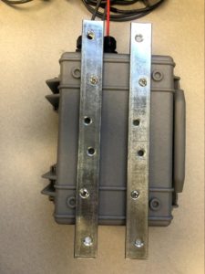
- To mount the monitoring station in the field, we added two mending plates to the back of the case. We drilled holes in the back of the box using a 5/32” drill bit. We used #8 flat head screws, lock nuts, and bonded sealing washers to secure the mending plates (See Table 1 for specifics on parts). We chose to mount the Pelican case using these external brackets instead of strapping a U-bolt or similar through the case because this approach does not require us to take out the box contents for installation.
- We placed the pressure transducer and temperature sensor in a housing which allowed them to be exposed to the water via the breather vent, while being weighed down and protected from solids.
- We put the two sensors into the breather vent, making sure that nothing was touching the pressure sensor.
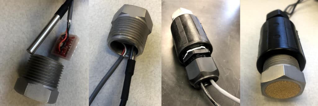
NOTE: After our initial deployment of the sensors, we realized that the metal in these breather vents was not as inert as advertised. We observed some oxidation that destroyed one of our sensors, so we switch them with PVC end caps with holes drilled in the bottom. The lighter weight of the PVC end caps made the sensor a little harder to submerge upon installation, but once they are filled with water they seem to perform just fine. - We used a PVC reducer to connect the breather vent to the ¾” multi-cord grip. The cables were passed through the cord grip to reach the box. (Not pictured, but we recommend that you drill a few holes around the PVC reducer to increase water flow through the housing.)
- We put the two sensors into the breather vent, making sure that nothing was touching the pressure sensor.
- The solar panel cable, temperature sensor cable, and pressure transducer cable were put through the ⅜” cord grips and attached to screw terminals on the inside of the case. We used Grove connectors to connect the screw terminals to the Mayfly logger.
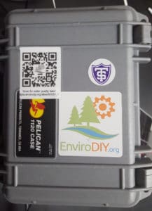
- Lastly, we added stickers to represent our affiliations and a QR code so people can look at the data from each station.


Deploying data loggers
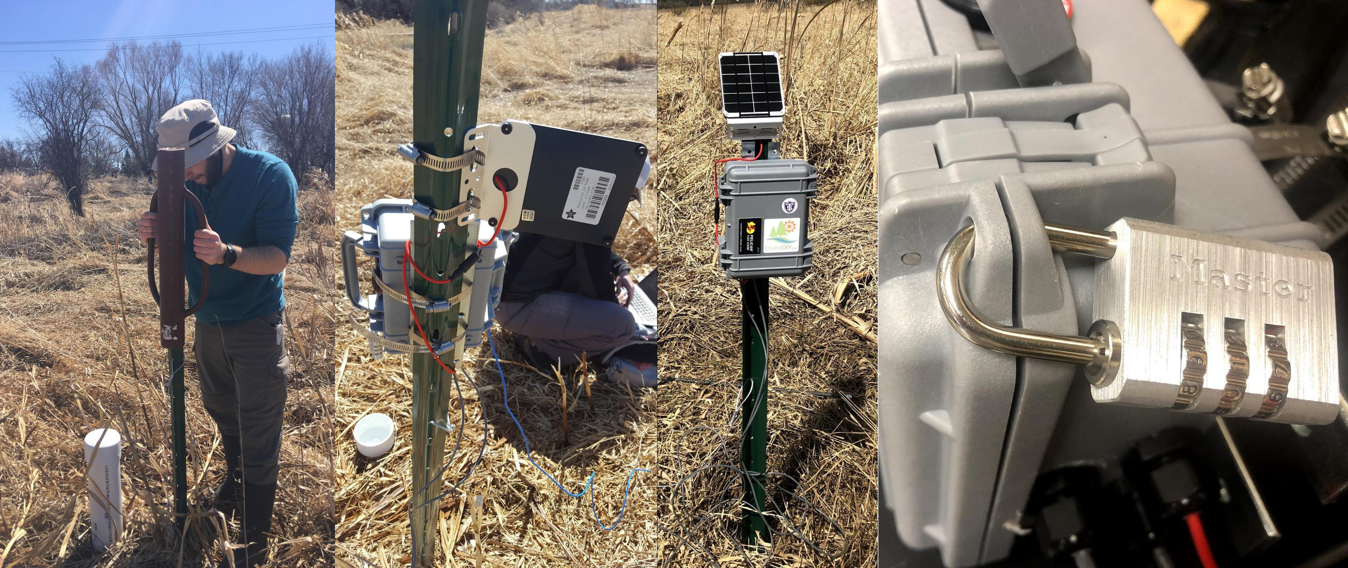
We deployed the data loggers at existing piezometers in mid-May when conditions were favorable (unfrozen water). We tested the monitoring stations and protective encasings with the modular code and data sharing portal before deployment to ensure the data loggers were working properly and the monitoring equipment was secure.
- We drove 6 ft. U-posts into the ground near each piezometer.
- We attached the pelican case to the U-post using hose clamps. Also, we mounted the solar panel above the pelican cases using hose clamps.
- To secure the monitoring station, we used a padlock and cable.
Data Results
Our data is being transmitted using a cellular network to data.enviroDIY.org. We selected which variables to send to the website and for simplicity, which ones to only log to the SD card. Once the data is on the website, we can track it in realtime and download the data. Our stations can be found under “University of St. Thomas”. Here are links to some of our stations:
Well 2. http://data.envirodiy.org/sites/BIXBY_2/
Well 7. http://data.envirodiy.org/sites/BIXBY_7/
Table 1. Sources of materials and software used, and sensor accuracy
| Materials and Software | Source and accuracy |
| Mayfly 1284p data logger microcontroller | EnviroDIY https://www.amazon.com/EnviroDIY-Mayfly-Logger-Arduino-Compatible/dp/B01F9B4WCG/ |
| Arduino programming software | Arduino https://www.arduino.cc/en/Main/Software |
| GitHub EnviroDIY Modular Sensors repository | GitHub https://github.com/ehost11/EnviroDIY_Mayfly_Logger |
| BME280 pressure sensor breakout | SparkFun https://www.sparkfun.com/products/13676 error = +/-100 Pa or +/- 0.015 psi |
| MS5803-14BA Pressure Sensor Breakout Board | SparkFun https://www.sparkfun.com/products/12909 error = +/- 0.2 mbar or +/- 2 mm change in water level |
| DS18B20 waterproof digital temperature sensor | Adafruit
https://www.adafruit.com/product/381 +/- 0.5°C |
| GPRSbee rev.6 cell wireless module | SODAQ |
| SIM Card | Hologram |
| Medium 6V 2W Solar panel – 2.0 Watt | Adafruit https://www.adafruit.com/product/200 |
| Lithium Ion Battery – 3.7v 2000mAh w/ pre-attached 2-pin JST-PH connector | Adafruit https://www.adafruit.com/products/2011 |
| Pelican 1120 case | Amazon
https://www.amazon.com/Pelican-1120-Case-Camera-Desert/dp/B0015RTXW8?th=1 |
| Cord Grips (⅜ NPT) | McMaster-Carr |
| Cord Grips (¾ NPT) | McMaster-Carr |
| Epoxy | Buehler EpoThin but Scotch-Weld EC2216 may be a better option. |
| Breather Vent (1 NPT) | McMaster-Carr |
| Pipe Fitting (reducer) | McMaster-Carr https://www.mcmaster.com/#46885k221/=1bwd0tu |
| Piezometer | Multiple sources |
| Mending Plates | https://www.homedepot.com/p/Everbilt-10-in-Zinc-Plated-Mending-Plate-15390/202034036 |
| Flat head screws | https://www.homedepot.com/p/Everbilt-8-32-x-3-4-in-Phillips-Flat-Head-Machine-Screws-5-Pack-33461/202706457 |
| Lock nuts | https://www.homedepot.com/p/Everbilt-8-32-Coarse-Stainless-Steel-Nylon-Lock-Nut-4-per-Pack-800101/204274164 |
| Bonded sealing washers | https://www.homedepot.com/p/Everbilt-8-Galvanized-Bonded-Sealing-Washer-4-Piece-806708/204276435 |
| 6ft U-pole | Home Depot |
| Hose Clamps | Home Depot |
neilh20
Gosh a great discussion and fantastic to see the detail and how to deploy a rugged Mayfly.
I made a depth sensor some years ago – so appreciate the detail described.
The first time I did it, I solved the sensor problem with a costly arrangement – a raw MSI sensor with an O-ring, and then a custom designed brass housing – it did work well as a rugged sensor for surface water streams. But cost was high for the custom brass housing.
So very impressed with your successes, and the conclusion of the value in sensors, and buy them if available 🙂 (and have the budget).
I have since tried some other sensor configurations, looking for a low cost way of translating physical water depth measurement with a specific accuracy to a traceable number – and its definitely a very specific challenge – water depth to physical units over say an SDI line.
One of the issues with sensors, always there, is the accuracy of the measurement and what is it dependent on, and what other events (like lightening) may cause a problem.
The accuracy – which is really % inaccuracy – is not only how the raw sensors physical readings map to specific units, but how repeatable they are, and for the real world over what temperature range. Ground water is typically a constant temperature and so shouldn’t introduce much variation there. However absolute pressure measurements need an atmospheric compensator measurement, that is then dependent on a wide range of atmospheric measurements. A colleague using a Hobo Onset Absolute pressure device, buried the temperature compensated barometeric measurement device at the foot of the main logging unit to keep the temperature as constant as possible.
For any sensor, you really want to be clear about what accuracy you want in the measurement system, and over what range of measurements. One option I’ve thinking about maybe a variable accuracy.
That is, is the absolute depth from base of the sensor only needs a loose requirement, but the accuracy at the low end of the scale needs to have a greater accuracy for changes over 1week. So I’m looking for a confidence in measuring daily variations, as well as peak measurements (its for a surface water stream)
One thought I’ve had is using a couple of low cost sensors together that measure the physical parameters slightly differently – one could be low cost air pressure sensor with a simple port (MP3V5010) and the other a capacitance wire.
The wire is easier to seal but way problematic to manage a calibrated reading – but indicates changes in water depth independent of temperature. The wire sensor only works over a limited range possible 1m and needs to be vertical
The air pressure sensor with a plastic tube port, and a plastic tube that has a high molecular weight inert silica gel (an idea from a tech support person at a sensor company) to transmit the water pressure and isolate the water from the electronics.
Then the issue becomes sealing the electronics in a water tight container.
What experience has taught me, is figure out how to do layered sealing – a mechanical layer, and then 2 layers of water sealing. If it can be lowenough cost then epoxy all the electronics.
Low water permeability epoxy (EpoxiesEtc) are expensive and there needs to be a simple way of mixing it and using it.
https://www.epoxies.com/_resources/common/userfiles/file/Epoxies_WP_AdhesiveMixingErrors_v8.pdf
So one idea for sealing/epoxying and using very little, is for all the electronics to fit in a 1″ sch 40 tube, then encase the electronics in a 1″ heatshrink. Fold the heatshrink at each end and apply the mixed epoxy in the fold, so using a double seal – the fold (with a small plastic tube running through) and then epoxy each side of the fold. Then activate the heatshrink with a heatgun to shrink it round the electronics. Then fill in the low volume center with epoxy and finally fold at top with wires/plastic pipe transiting the protective fold. So apologies, a bit difficult to describe and lots of small issues to get right.
So I did make one prototype, and had to put it aside when something else came up, and hope to get back to it …. but I share it in case anybody else is thinking about it. It doesn’t look much ….
http://www.envirodiy.org/wp-content/uploads/ProbeScFront.jpg – Water Depth probe using gas sensor
http://www.envirodiy.org/wp-content/uploads/ProbeScTop.jpg – Top of water depth sensor – prototype using TeensyLC – final device would be enclosed
And the processor with RTC, 16bit ADC & accurate ADC Ref, MKL27Z256VL https://www.digikey.com/products/en?keywords=MKL27Z256VL
I based the prototype electronics on a TeensyLC – with a target of using the Cortex MO MKL27X256 and SDI interface.
I can share more details if anybody is interested.
back to the post – thanks for sharing, and all the magic sources of the little stuff to get it deployed. Yeah!!!