
Home › Forums › Mayfly Data Logger › Battery Measurement accuracy
- This topic has 3 replies, 1 voice, and was last updated 2020-10-15 at 6:04 PM by
 neilh20.
-
AuthorPosts
-
-
2020-06-03 at 12:07 PM #14181
@shicks, I’m just wondering if you have the range of measurement accuracy for measuring batteryV, when running off the battery.
I’m using Mayfly 0.5b, but getting some strange results with Q1/FDN340P not turning on, just the FDN340 diode conducting and U2/SPX3819 actually 3.18V.
thanks
-
2020-06-03 at 8:56 PM #14182
So just checking, the Vbat voltage range. I’ve an application that doesn’t have a solar panel. I’m trying to figure out 1) can a LiSOCl2 3.6V 19Ahr be used 2) 3*D Mn 18Ahr 3) generically characterize the LiPo measured Voltage,
So I’m finding for some reason there is a need for 0.55V overhead from the processors 3.3V. Seems this the LDO and the MOSFET.
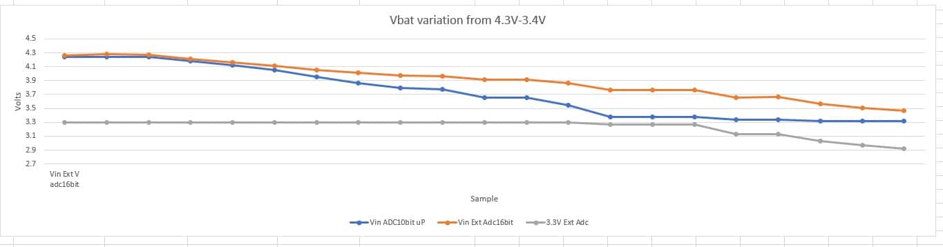
I’ve generated some data, graph below. This is a miniumium load, of the Mayfly taking a measurement every two minutes, and sleeping inbetween. Its measuring the Vbatt through uP A6 (blue line), then ADS1115 through a divider 1M/1M measuring the Vbat (orange line) and also the processors 3.3V (grey line)
I also added a low ESR 680uF cap to V_batt (Digikey 732-9079-1-ND ) to buffer any current pulls. Though under V_batt=3.45V the processor starts to reset.
My method is for an FTDI 3.3 cable to J2. I’ve disconnected J2-4/Vusb and J2-1/DTR. No USB cable. Variable power supply connected to JP1. Then vary the power supply Vbatt, measure externally with a Meterman 37XR volt meter to set the voltage, wait for a measurement to show on the TTY. Then drop the voltage and repeat.
The orangle line is accurate, the blue starts to droop under a real 4.1V, and flattens underneath a real 3.8V, as the 3.3V then starts to droop.
So I’m wonder if you have seen the same and any thoughts on the 0.55V overhead. That kinda eliminates the compact LiSOCl2 battery for me.
Attachments:
-
2020-06-04 at 5:42 PM #14184
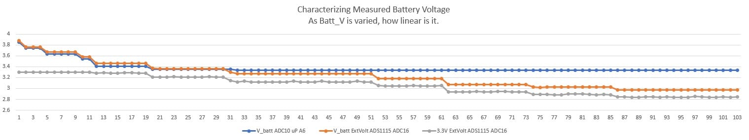
Here is some new data. I had the FTDI cable connected, and seems like it was influencing things somehow. I cut the RX (always high ~ 3.5V) and that changed the way Q1 is turned on. Still not sure why. I removed the FTDI altogether and repeated the readings.
The Mayfly will now continue operating to V_batt = 3.00V, Proc resets when I drop to 2.95V (motioning with a reasonably professional Meterman 37XR voltmeter).
The overhead/buffer difference V_batt &rail3.3V is now about 0.15V, probably mostly the SPX3819.
However it does show that the mega1284 A6 measurement is only linear to about 3.5V.
The 2nd graph shows the difference between V_Batt and 3.3V rail
I’ve added the .xls with the readings.
-
2020-10-15 at 6:04 PM #14667
So just to add some more characterization measurements.
I’m using a Mayfly Sn 20395, and attempting to characterize what range the readings from the Mayfly ADC Vbat are linear when it is only powered from Vbat. I’ve put a resistor network on the extV to the LiIon batter, to halve the voltage to keep it within the Vcc range for the ADS1115. Initially I used 100K//100K – and verified the output is linear.
I’ve connected an external powersupply to the Vbat, an external Meter (Materman 37XR) and then making measurements
Power supply to Mayfly JP1 Vbat (instead of LiIon)
Adjust power supply voltage to desired V measured on Meter.My conclusion is that the Mayfly Vbat becomes nonlinear under 4.0V.
TimeStamp Meter extVbat adcVbat 12:28:00 4.225 4.208 4.291 12:30:00 4.103 4.090 4.139 12:32:00 4.106 4.092 4.139 12:34:00 4.00 3.989 3.957 12:36:00 3.90 3.889 3.760 12:38:00 3.80 3.793 3.563 (break) 13:22:00 3.79 3.794 3.578 13:24:00 3.70 3.691 3.517
-
-
AuthorPosts


- You must be logged in to reply to this topic.