
Home › Forums › Mayfly Data Logger › Testing power consumption
- This topic has 13 replies, 4 voices, and was last updated 2021-04-07 at 11:29 AM by
 Sara Damiano.
-
AuthorPosts
-
-
2021-03-12 at 1:57 PM #15247
Hi all,
I’ve been doing some testing to measure the amount of power consumed by my Mayfly during various modes, and thought I’d share my results here. I’m interested in any and all feedback from the community.
I’m using the SparkFun coulomb counter that I’ve plugged into a spare Mayfly, which reports via USB to my laptop. Its set up to sample the current flow between a LiPo and my subject Mayfly with LTE modem and a sensor attached. These are the numbers I’ve come up with so far:Turner Turbidity Plus sensor – due to the demands of its wiper, this was my motivation for pursuing power measurements. I wanted to know how often I could run the wiper without draining the battery too quickly. Each wiper cycle takes about 8 seconds, during which it averages 109 mA.
During sleep, the Mayfly is consuming 6.7mA.
During LTE modem usage, I’m seeing 35 mA average during each modem-on, transmit data, modem-off cycle, which takes about 50 seconds per sampling interval.
Putting all of these together, and with a hypothetical 15-minute sampling interval, I’ve calculated that my circuit should consume 224 milliamp-hours per day. I need to do a bit more integration testing to try to confirm this number.
-Matt
-
2021-03-12 at 3:49 PM #15248
It sounds like your Mayfly is not actually going to sleep. An idle Mayfly will use around 6.5mA, and a sleeping Mayfly will use between 0.25mA and 0.5mA, depending on whether you’ve got a microSD card in the slot and the type of card. Here’s the power consumption results from Mayfly current tests:
Mayfly current when board is powered and idle: 6.5 mA
Mayfly current when MCU put to sleep and no microSD card in socket: 0.27 mA (or 270 uA)
Mayfly current when asleep with microSD card in the socket: 0.43 mA (or 430 uA) -
2021-03-12 at 9:30 PM #15252
Gosh @shicks that is great to hear. I wonder would you share how you made the sleep measurements with the microSD present. Any sketches for putting the mega1284 to sleep. Getting to 0.5mA would be fantastic!
Matt Interesting real data with a coulomb counter. Great stuff.
My current measurements on 0.28.01 for sleep are 2.5mA . I haven’t got a test setup for other modes at this point, but probably will have in the next couple of weeks.
For my current measurements I run it only from the battery and put a Adafruit INA219 in series, with a simple driver polling once a second, running on a separate Mayfly and then visually monitor current.
I’ve put together a spreadsheet for how power is used. I tend to calculate in mAseconds and then of course 3600mAseconds = 1mAhr.
Since I’m also wanting to tweak production code, I need debugging. I modified the FTDI cable so that only the processor Tx and the Gnd are connected, and debug output will advertise what state the processor is in. For an FTDI connector – male to male pins and just snip all pins except critical ones.
So from the spread sheet, for sampling period 900sec, using Readings 6.5mA@10secs, LTE 35mA@50secs,
Then for 24 hrs, 96*15minutes
sleep at 6mAs the calculation is 182mAHrs close to yours
sleep at 2.5mA then 104mAhrs
sleep at 0.5mA 59.6mAhrs ~ (I want it!)
Attachments:
-
2021-03-15 at 8:10 PM #15259
@shicks Thanks for those details. I wonder whether it could be the turbidity sensor, rather than the Mayfly, that’s actually drawing power, but I wouldn’t have thought it could do that while (or if) the Mayfly is sleeping. A bit more about my circuit:
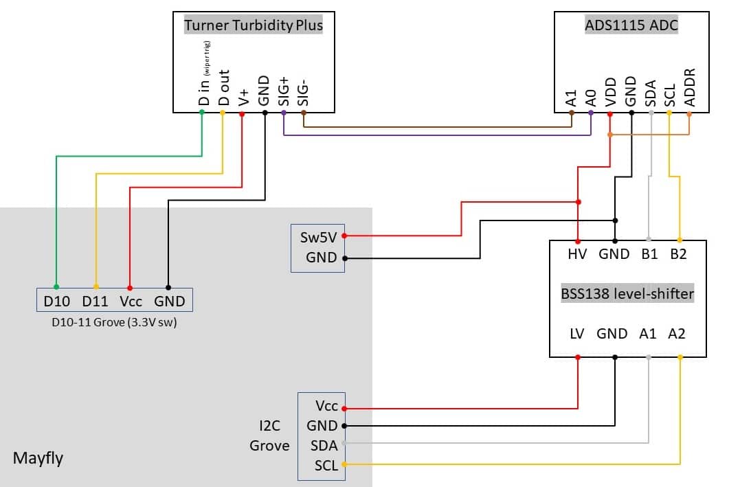
I’m powering the Turner from Mayfly’s switched 3V3. The Turner’s analog output is 0-5V, which I’ve connected to an external ADS1115 ADC. The Mayfly’s communicates to the ADC over I2C via a logic level shifter. The Turner also has a digital input to trigger its wiper, and a digital output that signals when the wiper is in its home position.
I’ve attached a wiring schematic. Does anything jump out that could be leaking current during sleep?
@neilh20 Thanks for the feedback, and I’ve got a very similar spreadsheet! I’ve also just received the parts for a FTDI cable to get serial output without supplying power – thanks for your work with this!Matt
Trout Unlimited
Attachments:
-
2021-03-15 at 9:20 PM #15261
If the “Switched 3v3” or “Switched 5v” is turned off, then nothing connected to those pins will be drawing power. But if your Mayfly board is not actually going into deep sleep, then it’s sitting in idle mode instead of actually sleeping, and that’s why it’s drawing 6ma. Wasn’t there some recent threads about how the I2C device was keeping the board from sleeping properly?
What’s the reason for having a separate ADC board? Are you just worried about reading a voltage greater than 3.3v with your Mayfly onboard ADC? Because if that’s the only reason, then it would be easier to just put a resistor divider on the sensor output and connect the center of it to your Mayfly ‘sADS1115. If you pick 2 perfectly matched resistors (like 10k) then you simply double the ADS reading to give you the actual sensor voltage.
-
2021-03-16 at 11:25 AM #15264
@mbarney an observation, the power is being turned off on the off board ADS1115, but not for the Turner. The ADS1115 Analog inputs are only specified for Vdd+0.3V. If either of the Turners outputs are above this, then it will feed through to the ADS1115 Vdd Sw5V. Probably won’t account for what your are seeing.
I found a I needed to know when in sleep v current consumption, so used the Ttty to know when its in sleep mode, and to measure the current at that time. (I have Adafruits INA219)
-
2021-03-16 at 5:46 PM #15268
@shicks The previous thread about I2C power that I’m aware of was when I learned that the jumper on the I2C grove port needs to remain in the constantly-powered position, otherwise the Wire library crashes, at least with certain sensors, including the Turner.
I *think* my Mayfly is sleeping: All LEDs switch off, if that means anything. If I connect to USB for serial output (all other testing has been lipo-powered, with no USB connection) and turn on debugging in LoggerBase.h, the traces indicate that it sleeps at the end of sampling:
12345678910111213141516171819202122232425262728293031323334353614:22:00.408 > ... zzzZZ Processor is now awake! <--LoggerBase14:22:00.408 > Current Unix Timestamp: 1615900920 -> 2021-03-16T13:22:00-07:00 <--LoggerBase14:22:00.408 > Logging interval in seconds: 120 <--LoggerBase14:22:00.408 > Mod of Logging Interval: 0 <--LoggerBase14:22:00.408 > Time marked at (unix): 1615900920 <--LoggerBase14:22:00.408 > Time to log! <--LoggerBase14:22:00.408 > ------------------------------------------14:22:00.408 > Running a complete sensor update... <--LoggerBase14:22:11.536 > Successfully connected to SD Card with card/slave select on pin 12 <--LoggerBase14:22:11.564 > Opened existing file: TU_Boise_turbidity_2021-03-16.csv <--LoggerBase14:22:11.586 >14:22:11.587 > \/---- Line Saved to SD Card ----\/14:22:11.587 > 2021-03-16 13:22:00,9.40396,0.0328,4.882,22.75,-57,9014:22:11.587 >14:22:11.587 >14:22:11.618 > Waking up Digi XBee3 Cellular LTE-M ... <--LoggerBase14:22:12.834 > Connecting to the Internet... <--LoggerBase14:22:19.356 > Sending out remote data. <--LoggerBase14:22:19.357 >14:22:19.357 > Sending data to [ 0 ] data.envirodiy.org14:22:20.380 > POST /api/data-stream/ HTTP/1.114:22:20.440 > Host: data.envirodiy.org14:22:20.440 > TOKEN: cd004b10-01a5-4e77-83cb-6ebefdf3e37914:22:20.440 > Content-Length: 36714:22:20.440 > Content-Type: application/json14:22:20.440 >14:22:20.440 > {"sampling_feature":"5f73afcf-22e8-496a-a4dd-4ebf70bb81af","timestamp":"2021-03-16T13:22:00-07:00","2669cd98-28d1-4b26-8c19-90acf32dedcf":9.40396,"b5720e79-47c6-435a-a88d-d11b650c570d":0.0328,"6e63a9f8-b8e6-44c8-a1ed-63d074a0c7da":4.882,"c635d2db-1509-4e9d-a248-ca66f3aeb11a":22.75,"293fdffc-558d-450c-9c79-4021e56bf7cc":-57,"dd123f56-6009-42a0-b90b-a1b5f2862208":90}14:22:20.440 >14:22:22.973 > -- Response Code --14:22:22.974 > 20114:22:22.974 > Updating modem metadata... <--LoggerBase14:22:34.663 > Disconnecting from the Internet... <--LoggerBase14:22:35.349 > ------------------------------------------14:22:35.350 >14:22:35.350 > Setting alarm on DS3231 RTC for every minute. <--LoggerBase14:22:35.350 > Putting processor to sleep. ZZzzz... <--LoggerBaseOn the external ADC: Yes, I used it to accommodate the 5v max from the Turner. I was thinking that this would be more accurate than using a 2/3 voltage divider to drop 5V to ~3.3V. But it sounds like you’re suggesting a 1/1 divider that would simply halve the output voltage, which you would then double in code. FYI, I’m using differential signaling to sense the Turner’s output, to hopefully make it less susceptible to noise.
@neilh10 Note that the Turner is powered by switched 3V3 from the D10-11 Grove connector, so it should be getting powered off during sleep. Also, since the ADC is powered by 5V, the Turner’s 0-5V outputs will be within Vdd+0.3V.
-Matt
-
2021-03-16 at 8:52 PM #15269
@mbarney the trace looks good for the waking portion. What I see on my system is that it wakes every minute and then sleeps inbetween. So if you have it on a 15minute setting it will do above, then sleep/wake 14times. The current can be read when it goes to sleep.
For the differential case I would think you would have two sets of dividers. BTW total error is additive. So you can probably match the R, but whatever the error is eg 0.1% then the final error that gets introduced is 0.4% . It may not matter if you are looking for dynamic changes rather than absolute numbers.?
-
2021-03-19 at 12:58 PM #15294
Trying to track down and eliminate my my Mayfly’s excessive power draw during sleep, I rebuilt my circuit to use the Mayfly’s onboard ADS1115 via voltage dividers, but got the same results; my sleep current is still around 6 mA. However, I discovered that if I disconnect the Turner’s wiper trigger wire from D10, sleep current drops to around 0.5mA.
To initiate the Turner’s wiper cycle, you pulse its trigger line low for 50 milliseconds. My TurnerTurbidityPlus class (code below) derives from Sensor, and its setup() method sets the D10 pin high; then when it’s time for a measurement, its wake() function sets D10 low, delays 50 milliseconds, and sets it back to high. Is this code causing the current drain, and how can I eliminate it?
-Matt
123456789101112131415161718192021222324252627282930313233343536373839404142434445464748495051525354555657585960616263646566676869707172737475767778798081828384858687888990919293949596979899100101102103104105106107108109110111112113114115116117118119120121122123124125126127128129130131132133134135136137138139140141142143144145146147148149/*** @file TurnerTurbidityPlus.cpp* @copyright 2020 Stroud Water Research Center* Part of the EnviroDIY ModularSensors library for Arduino* @author Sara Geleskie Damiano <sdamiano@stroudcenter.org>* Adapted from TurnerCyclops by Matt Barney <mbarney@tu.org>* @brief Implements the TurnerTurbidityPlus class.*/#include "TurnerTurbidityPlus.h"#include <Adafruit_ADS1015.h>// The constructor - need the power pin, the data pin, and the calibration infoTurnerTurbidityPlus::TurnerTurbidityPlus(int8_t powerPin, int8_t wiperTriggerPin, adsDiffMux_t adsDiffMux,float conc_std, float volt_std, float volt_blank,uint8_t i2cAddress, adsGain_t PGA_gain,uint8_t measurementsToAverage, float voltageDividerFactor): Sensor("TurnerTurbidityPlus", TURBIDITY_PLUS_NUM_VARIABLES, TURBIDITY_PLUS_WARM_UP_TIME_MS,TURBIDITY_PLUS_STABILIZATION_TIME_MS, TURBIDITY_PLUS_MEASUREMENT_TIME_MS,powerPin, -1, measurementsToAverage) {_wiperTriggerPin = wiperTriggerPin;_adsDiffMux = adsDiffMux;_conc_std = conc_std;_volt_std = volt_std;_volt_blank = volt_blank;_i2cAddress = i2cAddress;_PGA_gain = PGA_gain;_voltageDividerFactor = voltageDividerFactor;}// DestructorTurnerTurbidityPlus::~TurnerTurbidityPlus() {}String TurnerTurbidityPlus::getSensorLocation(void) {#ifndef MS_USE_ADS1015String sensorLocation = F("ADS1115_0x");#elseString sensorLocation = F("ADS1015_0x");#endifsensorLocation += String(_i2cAddress, HEX);sensorLocation += F("_adsDiffMux");sensorLocation += String(_adsDiffMux);return sensorLocation;}void TurnerTurbidityPlus::runWiper() {// Turner Tubidity Plus wiper requires a 50ms LOW signal pulse to trigger one wiper rotation.// Also note: I was unable to trigger multiple rotations without pausing for ~540ms between them.MS_DBG(F("Initate TurbidityPlus wiper on"), getSensorLocation());digitalWrite(_wiperTriggerPin, LOW);delay(50);digitalWrite(_wiperTriggerPin, HIGH);// It takes ~7.5 sec for a rotation to complete. Wait for that to finish before continuing,// otherwise the sensor will get powered off before wipe completes, and any reading taken// during wiper cycle is invalid.delay(8000);MS_DBG(F("TurbidityPlus wiper cycle should be finished"));}bool TurnerTurbidityPlus::setup(void) {// Set up the wiper trigger pin, which is active-LOW.pinMode(_wiperTriggerPin, OUTPUT);digitalWrite(_wiperTriggerPin, HIGH);return Sensor::setup();}bool TurnerTurbidityPlus::wake(void) {// Run the wiper before taking a readingrunWiper();return Sensor::wake();}bool TurnerTurbidityPlus::addSingleMeasurementResult(void) {// Variables to store the results infloat adcVoltage = -9999;float calibResult = -9999;// Check a measurement was *successfully* started (status bit 6 set)// Only go on to get a result if it wasif (bitRead(_sensorStatus, 6)) {MS_DBG(getSensorNameAndLocation(), F("is reporting:"));// Create an Auxillary ADD object// We create and set up the ADC object here so that each sensor using// the ADC may set the gain appropriately without effecting others.#ifndef MS_USE_ADS1015Adafruit_ADS1115 ads(_i2cAddress); // Use this for the 16-bit version#elseAdafruit_ADS1015 ads(_i2cAddress); // Use this for the 12-bit version#endif// ADS Library default settings:// - TI1115 (16 bit)// - single-shot mode (powers down between conversions)// - 128 samples per second (8ms conversion time)// - 2/3 gain +/- 6.144V range (limited to VDD +0.3V max)// - TI1015 (12 bit)// - single-shot mode (powers down between conversions)// - 1600 samples per second (625µs conversion time)// - 2/3 gain +/- 6.144V range (limited to VDD +0.3V max)ads.setGain(_PGA_gain);// Begin ADCads.begin();// Print out the calibration curveMS_DBG(F(" Input calibration Curve:"), _volt_std, F("V at"), _conc_std,F(". "), _volt_blank, F("V blank."));// Read Analog to Digital Converter (ADC)// Taking this reading includes the 8ms conversion delay.// We're using the ADS1115 library's voltsPerBit() to do the bit-to-volts conversion// for usadcVoltage =ads.readADC_Differential(_adsDiffMux) * ads.voltsPerBit() * _voltageDividerFactor; // Getting the readingMS_DBG(F(" ads.readADC_Differential("), _adsDiffMux, F("):"),String(adcVoltage, 3));// The ADS1X15 outputs a max value corresponding to Vcc + 0.3Vif (adcVoltage < 5.3 && adcVoltage > -0.3) {// Skip results out of range// Apply the unique calibration curve for the given sensorcalibResult = (_conc_std / (_volt_std - _volt_blank)) *(adcVoltage - _volt_blank);MS_DBG(F(" calibResult:"), String(calibResult, 3));} else { // set invalid voltages back to -9999adcVoltage = -9999;}} else {MS_DBG(getSensorNameAndLocation(), F("is not currently measuring!"));}verifyAndAddMeasurementResult(TURBIDITY_PLUS_VAR_NUM, calibResult);verifyAndAddMeasurementResult(TURBIDITY_PLUS_VOLTAGE_VAR_NUM, adcVoltage);// Unset the time stamp for the beginning of this measurement_millisMeasurementRequested = 0;// Unset the status bits for a measurement request (bits 5 & 6)_sensorStatus &= 0b10011111;if (adcVoltage < 5.3 && adcVoltage > -0.3) {return true;} else {return false;}} -
2021-03-19 at 4:23 PM #15300
@mbarney its a common problem with low power, sleep circuits.
Just to be clear/restate what the issue is. When in “sleep” mode and powered off, all instrument pins (and actually all other processor pins) need to be set to output low, or input with preferably pull down.
On power-up, the pins are activated output and set high within 50mS so as to not trigger the wipe.
On power-down, its a race condition which to do first, and the global control of the power, but with a min 50mS pulse I would think you are safe to make the wiper pin low and hope that the power is turned off within 50mS.
KellerParent.cpp has ::powerUp() and ::powerDown() which is where I change the pins.
You are using ::setup() for setting the port direction, which is I think is run only once, so I would think you move the wiper setup to ::powerUp
Sounds like its coming along, and I’m fascinated that you are getting 0.5mA.
BTW with my FTDI cable setup, I just found the hardway that the Ftdi Rx pin (tx pin from processor) hadn’t been clipped off and on my stability test station; the 4.4Ah battery mysteriously suddenly drained down in about 3days and then recharged from he solar. It turns out my monitoring PC Win10 did some form of automatic update and then powered down. The FTDI cable also powered down, including this unclipped Rx pin, that then drained off the battery current. I only noticed after I had restarted the PC, and the monitoring, and then two days later was checking the results and saw the battery had mysteriously drained down and come back. So the purpose of stability monitoring is check for anomalous behaviour in a secure setting, so I needed to find out what had happened.
-
2021-03-19 at 4:48 PM #15303
I would do as Neil suggested and make sure the trigger pin for the Turner is set low before sleep.
We’ve had the same problem with RS485 adapters that pull power through the Tx/Rx lines. Because the stop bit is high those lines will stay high if you don’t force them low at the end. It’s kind-of a PITA with the Tx/Rx bits; you have to actually write it setting those low into your loop because ModularSensors doesn’t know anything about the Tx and Rx pins, only the serial stream.
It could also be that the wiper is causing a whole lot of noise on the line which is keeping the Mayfly awake (acting as a pin-change interrupt). But I think if that were the case you’d see the going to sleep/waking up lines continuously, not just once a minute. The once a minute thing is because the alarm on the DS3231 doesn’t allow for every x minutes, just at one exact time or every second, every minute, every hour, etc. To get it to wake only in 5 minutes (or 15 or whatever your logging interval is) you’d get the current time and then calculate and reset the alarm for 5 minutes in the future each time. Since the board should only wake for a few ms every minute, it seemed safer to use the every minute alarm than to reset it to a new time each time.
-
2021-03-19 at 7:51 PM #15304
Thanks to both of you for your responses! I think I had just figured out the cause of my problem right about the time you were posting them, but needed to continue refining and testing my code before replying.
What’s working now is:
- In the sensor’s setup() function, set trigger pin to an output
- at powerUp(), set pin HIGH
- at wake(), run the wiper (set pin LOW, wait 50ms, set pin HIGH)
- at powerDown(), set pin LOW
The wiper cycles as expected and sleep current is <0.7mA. The only exception seems to be that when the Mayfly wakes up at the first measurement cycle (not at startup), the wiper doesn’t run as expected. At all subsequent measurement cycles that I’ve watched, the wiper cycles properly.
@srgdamiano Sara, which of the following functions would you recommend as a best practice for where to change the pin value described above, at powerUp and powerDown, or at wake and sleep?
@neilh20 That’s funny on the FTDI cable (well, funny in hindsight) – ouch! 🙂Best,
Matt -
2021-03-31 at 11:07 AM #15345
@srgdamiano
Hi Sara, any advice on the question above, about powerUp/powerDown vs. wake/sleep?Matt
-
2021-04-07 at 11:29 AM #15354
I’d put it in the power up, since it’s supposed to happen right away and setting the pin is nearly instant and won’t slow down other things powering up.
-
-
AuthorPosts
- You must be logged in to reply to this topic.