
Loss of lives and property during river floods around the world could be reduced with more timely warnings of when and where water levels will rise.
River flood monitoring systems provide data for these warnings, and that data can also inform broader investigations in river science and management. Despite the extensive network of federal, state, and private sector river monitoring stations currently in use, most streams and rivers in the U.S. are unmonitored.
Filling these monitoring gaps requires monitoring systems with low size, weight, power consumption, and cost (SWaP-C). Moreover, flood monitoring systems must be capable of transmitting data from remote locations to the web. Many types of SWaP-C systems are available from commercial vendors, but there are few open source options that are accessible for iteration and enhancement by the public.
Stroud Water Research Center developed an open-source SWaP-C flood monitoring system that can be rapidly deployed from bridges or other near-channel structures.
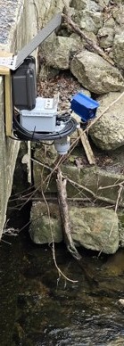
This post details the principal components, their operation, and assembly of the Open-source River Camera and Altimetry (ORCA). The key features of the ORCA (photo 1) are:
- Radar-based water level measurement.
- Photographs of the channel.
- Radio transmission of measurements and images to remote data portals.
- Solar power for continuous operation.
- Compact design.
- Relatively low cost.
Design Philosophy
Our goal was to build a low-cost, open-source station that could be transported easily and set up quickly. We evaluated a number of different camera systems and settled on the Geolux HydroCam because of its high-quality images (including infrared illuminated night photos), easy serial interface, and availability from their European supplier. The VegaPuls C21 radar sensor is a rugged, accurate distance sensor with SDI-12 output and fast sampling, making it easy to interface with our existing Arduino-based EnviroDIY Mayfly Data Logger.
The processing of the camera images required more resources than the Mayfly Data Logger could handle, so a new board called the Stonefly Data Logger was designed and fabricated, using a SAMD51 processor, and adding additional features to add extra capability beyond what the Mayfly boards offer (schematics, board files, and parts list on Github).
Like the Mayfly, the Stonefly features a Bee-compatible socket for adding telemetry modules, such as the Wi-Fi and cellular boards we have successfully used in the past. We also wrote new code enabling the use of MultiTech LoRa modules that couple with a LoRa base station to transmit data from the station without incurring cellular data fees.
The entire station setup operates on a rechargeable battery and a solar panel, enabling continuous remote operation.
List of Components
The approximate cost of all the equipment (minus the camera and radar sensor) was $550 USD in mid-2025.
| Part description | Notes |
|---|---|
| EnviroDIY Stonefly Data Logger | |
| EnviroDIY RS232 and Relay FeatherWing | |
| EnviroDIY 6-port multi-purpose screw terminal Grove adapter board | |
| EnviroDIY sim7080 LTEbee cellular board (optional) | |
| MultiTech LoRa module and antenna (optional) | MTDOT-915-X1P-SMA-1 and ANT-916-CW-RCS |
| 8 x 10 x 4 Polycarbonate Electrical Enclosure | Hammond MFG Model PCJ1084LF |
| Nylon submersible cord grips | 2 pieces 0.16″-0.31″, 1 piece 0.08″-0.24″ |
| 1/4″-20 stainless steel screws, nuts, and washers (five sets) | Talentcell PB120B1 |
| DC Barrel plug to screw terminal adapter | 2.1 mm x 5.5 mm |
| USB-A to bare wires cable | |
| Universal 1/4″ swivel mini ball head screw tripod mount | |
| 1/4″ female to M6 male threaded screw adapter | |
| 9W, 18V ETFE solar panel | Voltaic Systems model P108 |
| Large solar panel bracket and panel screw/washer set | Voltaic Systems BK103 and K-MT-BK-ETFE |
| Female 3.5 x 1.1 mm solar extension cable with leads | Voltaic Systems part W045 |
| 1/4″-20 stainless steel screws, nuts, and washers (five sets) | |
| Vegapuls C21 radar sensor (configured with SDI-12 output) | (with AC-222-2XV mounting bracket) |
| Geolux HydroCam Camera |
Assembly
Tools required for assembling the ORCA:
- Small-tip flat blade screwdriver.
- Medium Phillips screwdriver.
- Adjustable (or 7/16″) wrench.
- Wire snips.
Step 1: Enclosure Assembly
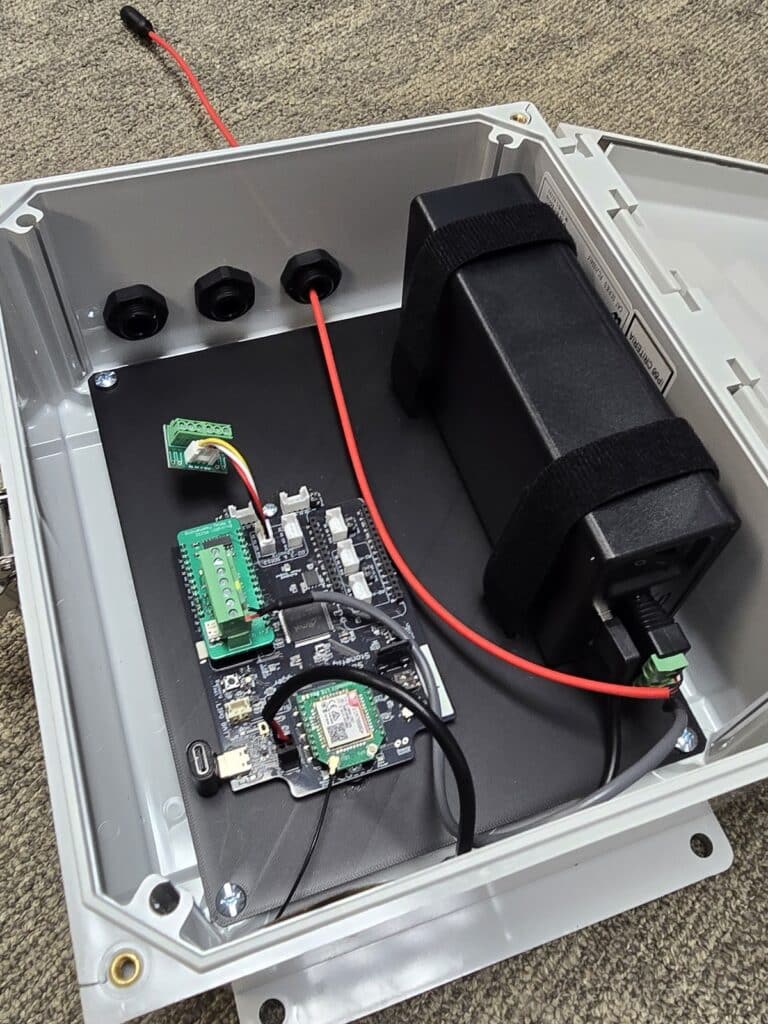
The EnviroDIY Stonefly board is mounted to a custom black PETG panel using two short M3 screws. Black velcro straps are used to hold the large Lipo battery pack in place. The enclosure (photo 2) is a weatherproof polycarbonate case with a lockable latch.
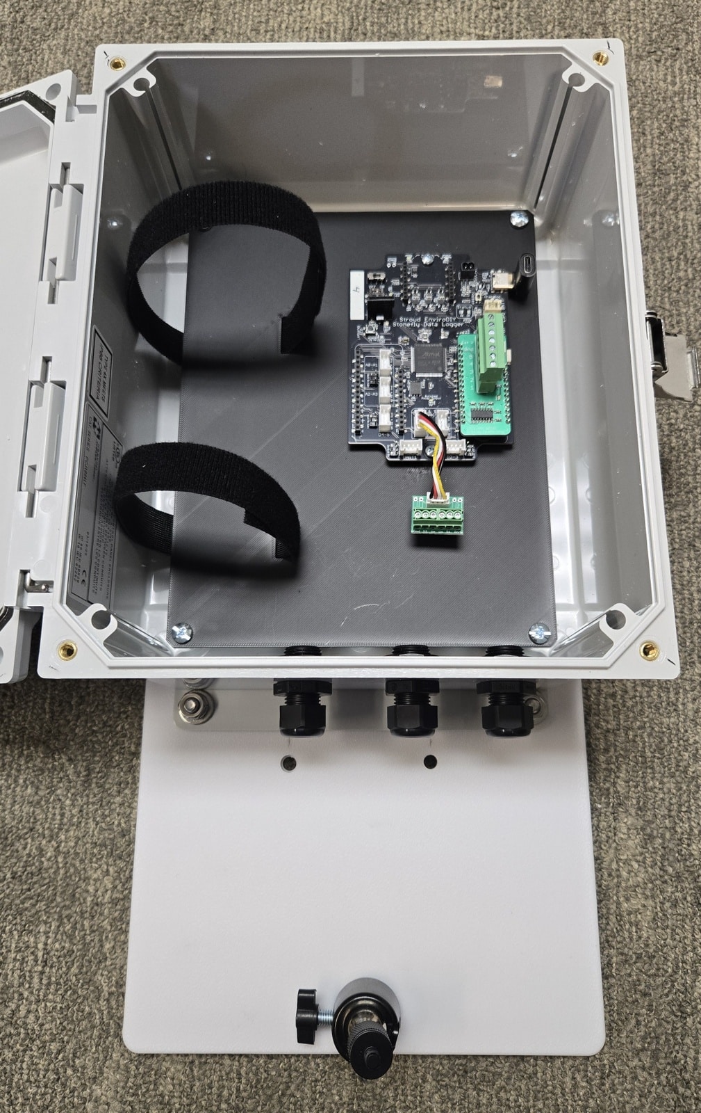
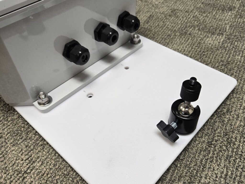
Three cable glands are attached to one end of the enclosure (photo 3). The smallest gland is for the solar panel cable, and the other two are for the camera and radar sensor cables. A white 8-inch panel is bolted to the mounting flange. There are two 1/4″ holes near the case for mounting the radar sensor (on the bottom) and one hole on the far edge for the camera swivel mount on top.
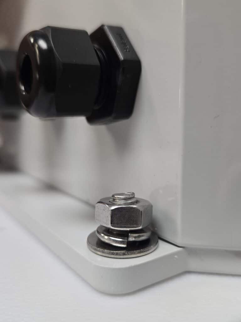
The sensor/camera panel gets bolted to the mounting flange of the enclosure using two stainless steel 1/4″-20 screws, a flat washer, a lock washer, and a nut. Be sure to assemble the washers in the order shown in photo 4:
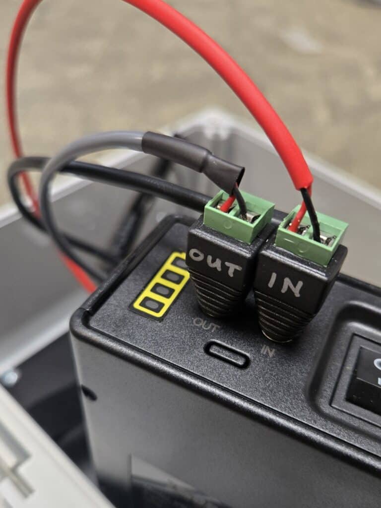
Step 2: Connecting Cables to the Battery
Inside the enclosure, the large LiPo battery pack is connected to various cables (photo 5). The red solar panel cable connects to a barrel plug marked “IN” and is connected to the jack on the battery pack labeled “IN.” This is the charging input to the battery pack, which, when deployed with the 18V solar panel, will keep the pack charged. Note that the pack only charges when the pack’s power switch is turned to the ON position. You can also charge the pack with the wall transformer provided by the manufacturer. Keep the battery pack’s power switch turned OFF until after assembly is done and the station is ready to be powered up.
The short gray cable goes to the “OUT” barrel plug and connects to the battery’s “OUT” jack. This provides a 12V DC output from the battery pack. This cable is what will provide the 12V power source for the camera.
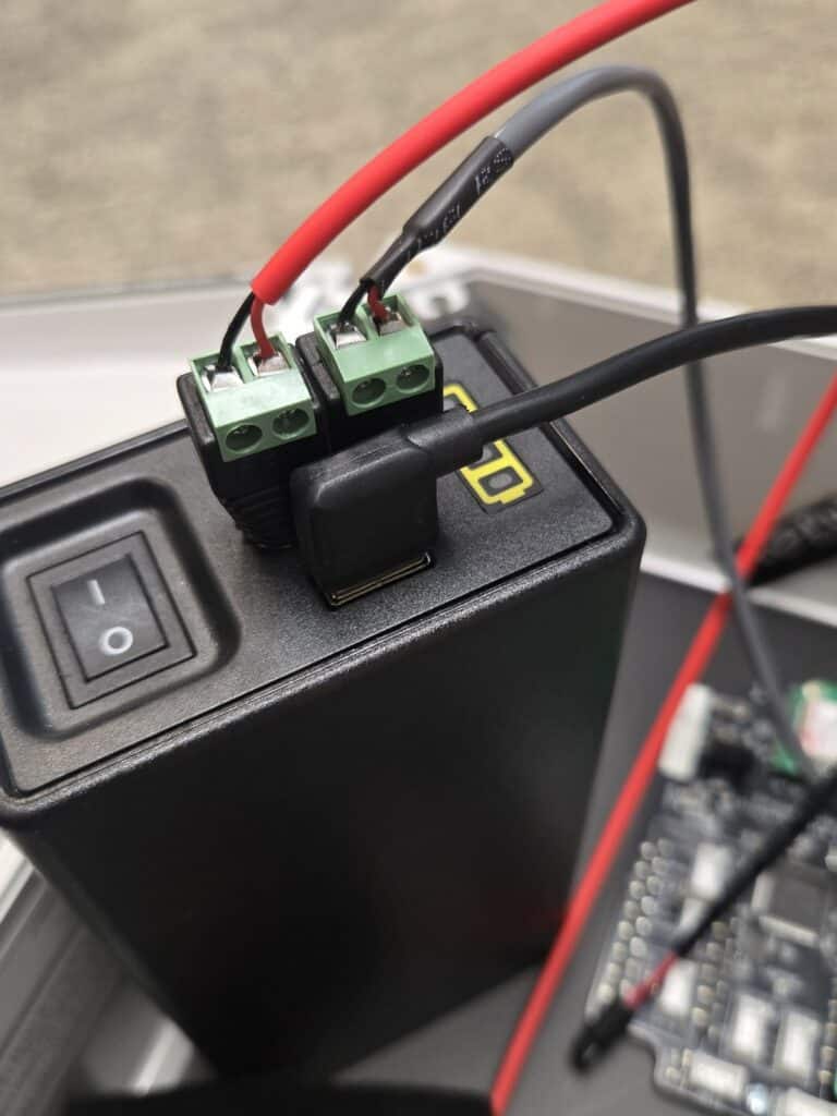
A right-angle USB cable gets connected to the battery pack to provide 5V DC power to the Stonefly board (photo 6).
Place the battery pack in the enclosure as shown in Photo 7 below, and adjust the straps so that they look like the ones shown.
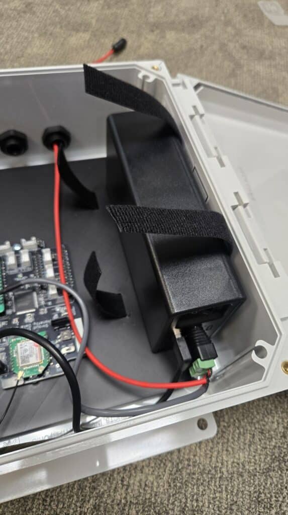
Using one hand to hold down the shorter piece of the strap on the side of the battery, use the other hand to tightly pull the other end of the strap over the top of the battery and down the side, securing it on top of the bottom piece of velcro. Adjust as necessary to get a nice, tight fit (photo 8) that will prevent the battery from shifting sideways or falling over.
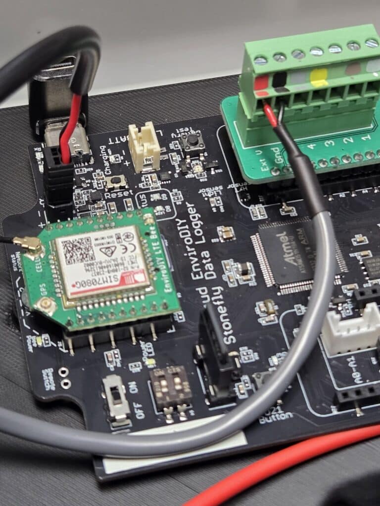
Step 3: Connecting cables to the Stonefly Data Logger
Plug the black battery cable (the one with the USB plug) into the Stonefly, as shown in Photo 9 below. The black plug is polarized, so it will only go into the socket one way. The black polarized socket is labeled “SOLAR,” which is where a 6V solar panel can be connected to the Stonefly if it is being used with a standard 3.7V LiPo battery connected to the JST socket labeled “LIPO BATT.” However, since the Stonefly board in this system is being powered by the external 12V LiPo pack via its 5V USB output, it is best to connect power to it using the black SOLAR jack. This prevents the external battery from accidentally being sent a charging voltage when you connect your computer to the Stonefly’s USB-C jack during programming.
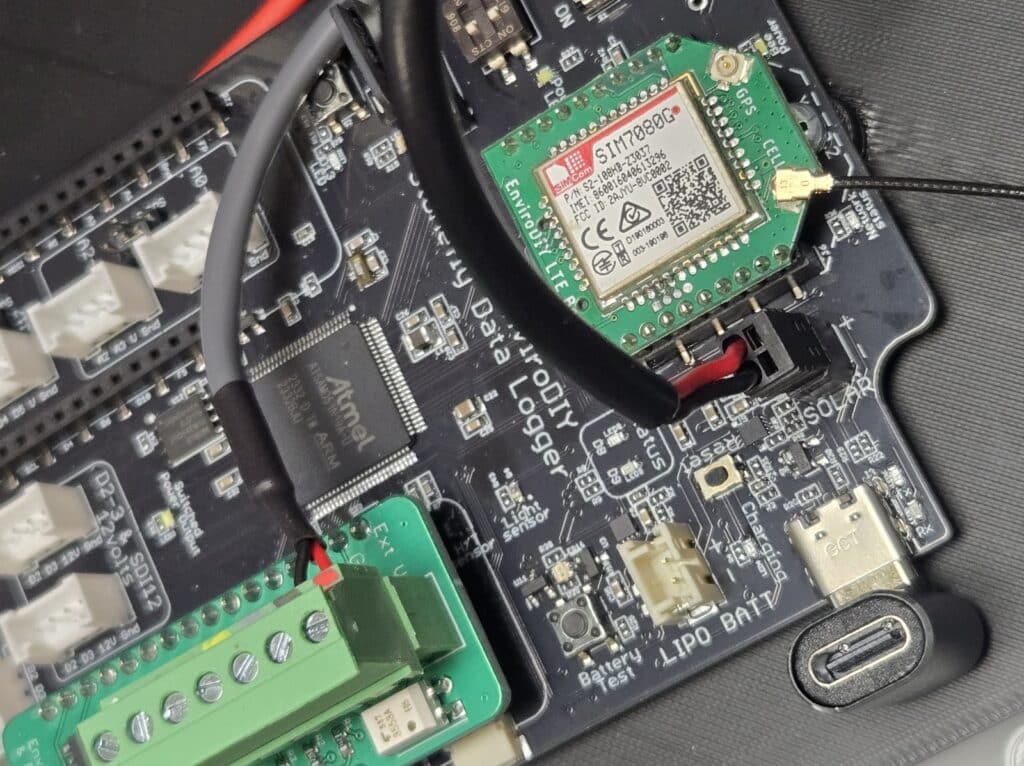
The gray cable from the battery pack OUT jack provides 12V power to the camera and needs to be connected to the green FeatherWing RS232/relay board that’s plugged into the Stonefly board. There are color-coded marks on the 7-pin screw terminal block showing which wires get connected. Insert the red and black wires into the appropriate terminals (labeled “Ext V” and “Gnd” as shown in Photo 10) and secure them by tightening the flat-head screw.
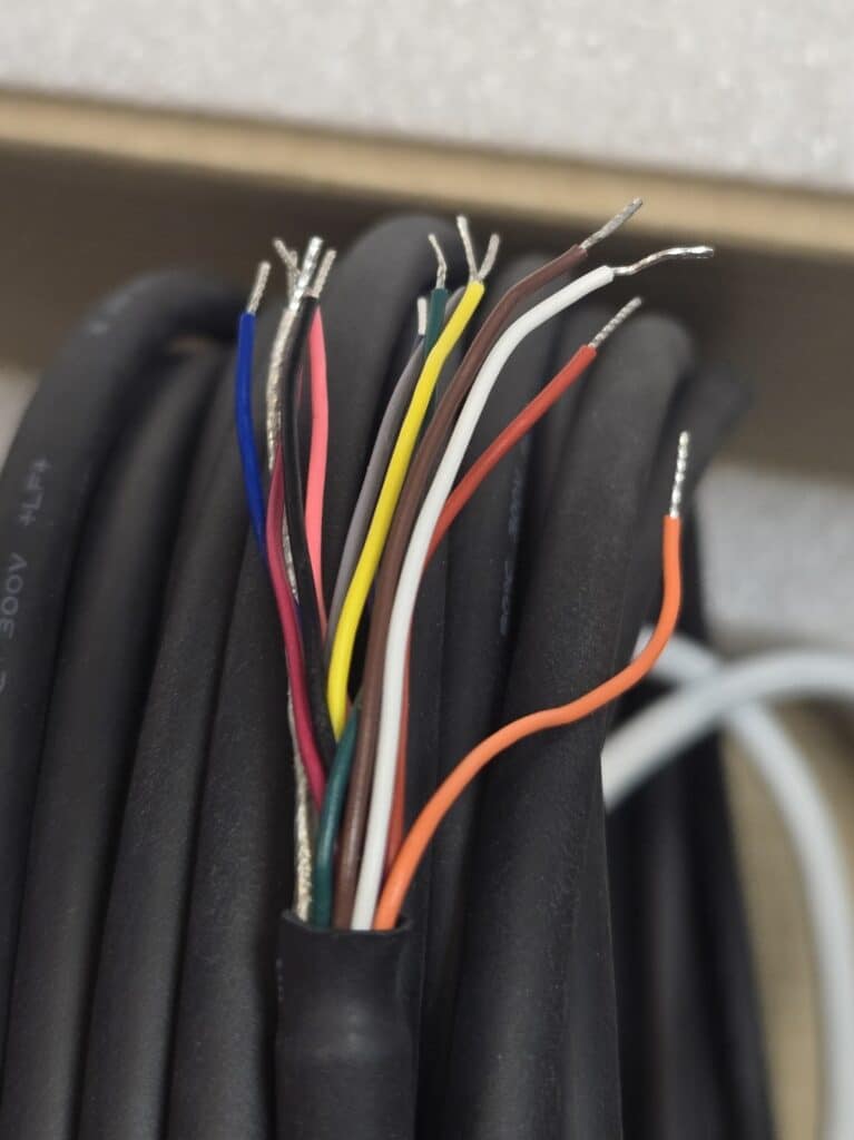
Step 4: Connecting the Camera
The HyrdoCam cable has 12 colored wires in it, as shown in Photo 11 below. Only five wires are needed for connection to the Stonefly via the FeatherWing interface board. They are white, brown, green, yellow, and gray. The other colors are not needed and should have the bare ends snipped off and protected from touching each other or anything else in the enclosure, especially the Stonefly board.
Feed the camera cable into the enclosure via either of the cable glands. Attach the five wires mentioned above to the appropriate color sockets on the screw terminal board using a small flat-blade screwdriver (Photo 12). If, for any reason, you need to easily disconnect the camera from the FeatherWing and Stonefly, the screw terminal block can be unplugged from the FeatherWing board by gently pulling up on the terminal block while holding the FeatherWing. You can also remove the FeatherWing board from the Stonefly, but note that the two long rows of pins must be placed exactly back in the socket below when reconnecting it.
Step 5: Connecting the Radar Sensor
The C21 radar sensor gets mounted to the bottom of the white panel using the adjustable mounting bracket provided by the manufacturer. Attach the bracket to the panel before inserting the sensor into the bracket. The bracket gets secured to the panel with the same 1/4″-20 screw/washer/lockwasher/nut combination as earlier. Once the bracket is secured, insert the radar sensor into the bracket’s large hole and tighten the black mounting nut by hand. The bracket has an adjustable hinge that allows you to orient the sensor vertically after mounting, and then tightening the screw on the hinge to keep it in the correct position, perpendicular to the surface being measured.
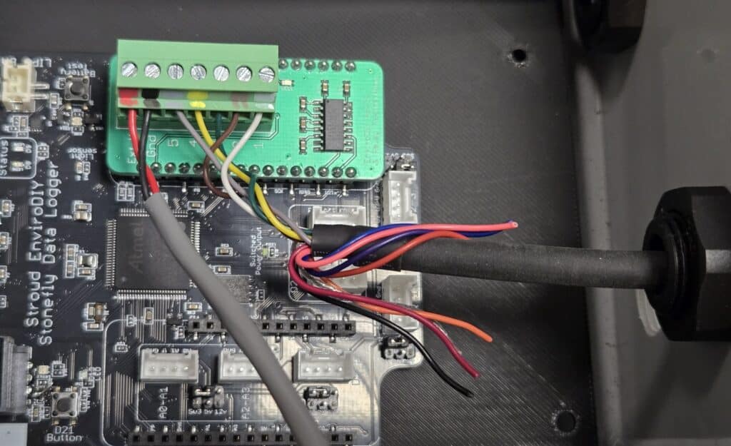
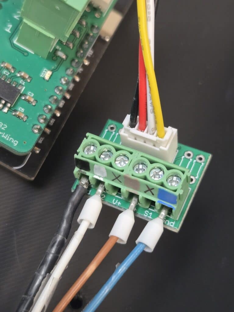
Insert the radar sensor cable into the other cable gland. The radar sensor cable has four wires: black, white, brown, and blue. There are four colored marks on the small green 6-pin screw terminal Grove adapter board, as shown in Photo 13 below. Connect the wires to the appropriate positions on the terminal board. A small 5 cm Grove cable is used to connect the terminal board to the Stonefly. It can be connected to either of the two Grove jacks in the center of the Stonefly labeled “D2-3 & SDI-12.”
Now that all the cables have been installed in the cable glands, tighten each gland by hand so that the cables are secure and will not cause damage to the Stonefly if something were to pull on the cables outside the enclosure.
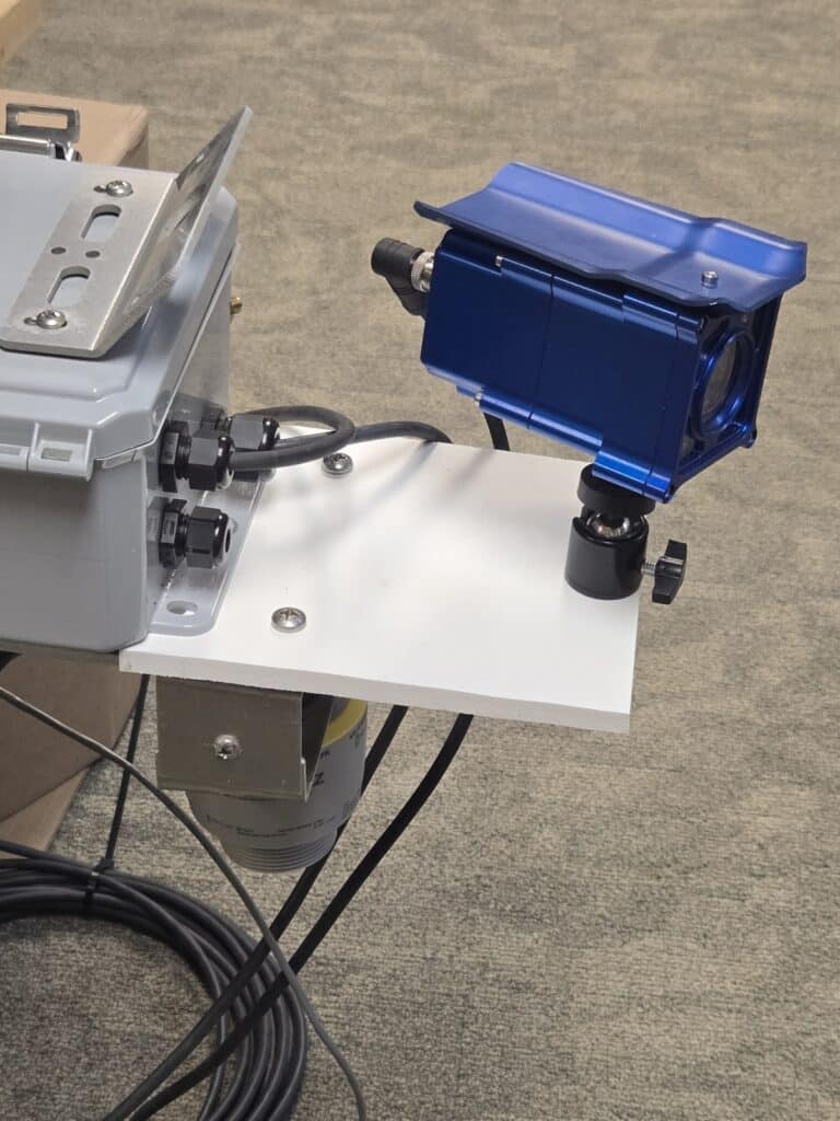
Step 6: Mounting the Camera
Screw the HydroCam camera onto the swivel mounting post (Photo 14). There are two threaded holes on the bottom of the camera. Use the one closest to the center of the camera so that it balances better on the post. Once the camera is pointed in the correct position, tighten the post’s adjustment screw gently by hand.
Connect the camera’s data cable to the back of the camera by plugging in the connector and screwing on the locking ring.
Step 7: Completion
The camera and radar sensor are now mounted and connected to the Stonefly board. The solar panel can be added by simply plugging the waterproof barrel plug from the panel’s cable into the barrel jack on the end of the red cable coming out of the enclosure.
There is a right-angle USB-C connector plugged into the Stonefly’s USB jack, allowing you to easily plug a USB-C cable into the Stonefly board for programming while it is mounted in the enclosure.
Important note: If a computer is connected to the Stonefly via the USB port, the Stonefly will be powered, as well as the radar sensor. However, the HydroCam camera will not receive any power unless the external Lipo battery pack is turned on via the power switch on the external pack.
Data Logger Programming
Refer to this GitHub code repository for instructions on running the Stonefly data logger with various telemetry methods and endpoints.
Deployment Considerations
- The ORCA was designed to be mounted on a bridge or structure above water; however, the end user is responsible for determining the best way to mount the enclosure, which will vary depending on each installation.
- The radar sensor must be mounted at least 8 inches horizontally from any vertical-oriented wall or bridge near the sensor.
- The camera angle can be adjusted with the knob on the side of the swivel mount.
- The solar panel should receive at least a few hours of direct sun each day, so mounting location and proximity to the enclosure will also vary for each site. Extension cables for the solar panel cable can be made or purchased from Voltaic Systems to allow for easy mounting of the panel in cases where more cable length is needed.
Funding
This effort was funded by the U.S. Geological Survey Next Generation Water Observing System Program through the Chesapeake Ecosystem Studies Unit of the National Park Service, Cooperative Agreement G24AC00055-01.
Questions? Please leave a comment below.
neilh20
Wow looks fascinating. While the SWaP-C mechanical looks so nice, and it’s the open-source software on opensource readable hardware that can make it so nicely extensible.
It’s great to see the Stonefly’s SAMD51 Arm Cortex M4 32-bit processor, as currently specified with an internal program flash 512Kbytes and ram of 192K. Though I have to say when it comes to real world programming, this type of program memory gets used up pretty quickly. It would be really nice to pay the extra few $ for double the memory 1,024Kbyte device. The schematic shows an external flash program memory of 8Mbyte, fantastic so maybe that’s the expansion. I ran out of the Mayfly’s 8bit AVR1284’s program memory of 128K some three years ago.
So, Wow! when is the Stonefly going to be available?
Its good to see all the other Mayfly’s specialties also on the Stonefly, and it looks like an extra “Feather” socket. Hopefully, that is the Adafruit’s feather “wing” board. It also looks like the solar input is going to be specified for higher voltage solar panels to 18V. I have often found that solar panels only get a brief period of sun at some periods of the year. Either limited solar in winter, or in summer deep in a forested canopy, a moving dappled solar patch, and need to harvest a good charge in short period of time.
I look forward to full Stonefly description.
While the title of this is “River Flood Monitoring System”, to me that implies it needs to be reliable. It suggests it’s going to be there, monitoring, and then possibly at the most challenging time – after rain has been coming down for a week, will it still be reliable, working?
While I blog a lot about the Mayfly and ModularSensors – I seem to be the only person who discusses reliability issues. I wonder if there could be more discussion about what it takes to have reliable deployments, based on the past network of deployed systems.
Look forward to exploring the Stonefly.