
Home › Forums › Environmental Sensors › Negative Voltage Reading from Single-ended ADC Using Apogee SP-212-SS Sensor
- This topic has 5 replies, 2 voices, and was last updated 2023-05-10 at 11:21 AM by
 Shannon Hicks.
-
AuthorPosts
-
-
2023-05-04 at 3:52 PM #17784
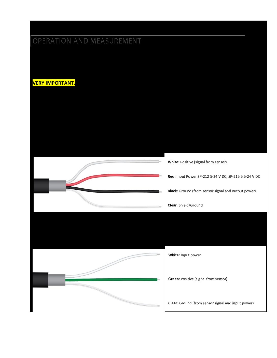
I am trying to get shortwave radiation readings from an Apogee pyranometer (SP-212-SS model). I am new to electronics and microcontrollers, so there could be a lot of places I am going wrong here. I am using a Mayfly version 1.1 as the data logger. To connect the sensor, I am using the Aux Analog grove terminals. I’ve attached a picture of my sensor wiring to show how I’ve connected the sensor to the Mayfly.
The manual for this sensor says that the input power is 5-24 V. I’ve attached the two pages from the manual that talk about the operation and measurement of the sensor. It says to take the mV output and multiply it by 0.8 to get the shortwave radiation (my serial number is above 10517). I am using the Adafruit_ADS1X15 library to read the ADC from the AA1 pin. I am not sure why, but my serial monitor is saying that the voltage is negative, and therefore I am getting a negative shortwave radiation. I took the sensor outside, and the output is adjusting if I have it in the shade or in the sun, so the sensor is responding. Again, I am very new to this, so I am likely missing something pretty simple. I think I am either using the ads.readADC_SingleEnded() function incorrectly, or I am setting up my sensor incorrectly. Any help would be great. Here is the code I’m using:
Arduino12345678910111213141516171819#include <Adafruit_ADS1X15.h>Adafruit_ADS1115 ads;void setup() {// put your setup code here, to run once:Serial.begin(9600);ads.begin();}void loop() {// put your main code here, to run repeatedly:int16_t adc1 = ads.readADC_SingleEnded(1);float voltage = adc1 * 0.1875;float ShortwaveRadiation = voltage * 0.8;Serial.print("Voltage: "); Serial.print(voltage); Serial.print(" mV; ");Serial.print("Shortwave Radiation: "); Serial.print(ShortwaveRadiation); Serial.println(" W/m2");delay(1000);}Thanks!
-
2023-05-04 at 7:51 PM #17787
First you should attach the sensor’s clear wire to the GND pin of the screw terminal board along with the black wire.
Second, the sensor needs at least 5 volts of excitation power, and the jumper setting of the Aux Analog Grove jacks in your photo is set to the default 3v position. You need to move that jumper to the 5v position. See the section on the Grove jack jumper settings in the middle of this page: https://www.envirodiy.org/mayfly/hardware/jumper-settings/
Third, the Grove jacks only receive power when the switched voltage regulators are turned on, which only happens when you set pin D22 high. You’ll need to add a line in your sketch to do that. If you want to take continuous readings, then it’s fine to leave D22 high, but it’ll use more power than if you turn if off when not in use, which is important if you want to make a sleeping logger that powers all the sensors down between readings. For constant power in your example, insert the following lines in your setup section after line 8:
digitalWrite(22, HIGH);
delay(1000);The delay line is to give the sensor a second to warm up. In general, you don’t want to start sampling as soon as a sensor receives power since various sensors need anywhere from 100ms to 45 seconds before a reading can be taken. Most sensor manuals will tell you what that number is, but for good measure, it’s good to wait at least a second for simple sensors, and adjust if you notice that it needs more or less time. There will be a little red LED in the lower left corner of the Mayfly that will be on anytime the Grove jacks are powered, indicating that the switched power is on. If you want to turn them off at any point, simply set pin 22 low.
Fourth, the ADS1115 aux analog input has 4 channels, and they start counting with 0 (zero). So your available channels are 0,1,2,and 3. In your photo, you’ve got the sensor output connected to the white wire of the uppermost Grove jack, which if you look at the labels next to the jack, is analog channel 0. So your code in lines 13-14 should be:
int16_t adc0 = ads.readADC_SingleEnded(0);
float voltage = adc0 * 0.1875;And as an aside, those sensor outputs can be pretty variable between readings on a partly-cloudy day or in a forest environment. In your example you’re sampling once every second. But if you deploy it for real-world monitoring and want to do 1- or 5-minute samples, we found it works well to do a loop of about 50 readings over 5 seconds to get a smoother representation of the actual light levels.
-
2023-05-08 at 11:48 AM #17791
Thank you for your reply! That definitely helped. I think the only thing I’m still confused on is the output channel. You mentioned that the white wire in the uppermost grove jack is connected to analog channel zero, but when I look at the board, the label next to that wire is AA1. If you could clear that up for me that would be great. Thanks for the help!
-
2023-05-08 at 11:53 AM #17792
You’re right, you correctly have your sensor’s signal white wire connected to the Grove cable white wire, which goes to the AA1 pin of the Aux Analog grove jack, so you can disregard my suggestion to change the ADS1115 code to adc0, and just leave those two lines as they were, using adc1.
-
2023-05-09 at 2:27 PM #17803
Okay sounds good. I was also wondering, Shannon, if you might be able to help me out with something. I’m looking to attach a suite of sensors to the Mayfly that have a mixture of analog outputs and digital outputs. I’m worried that I won’t be able to get all the sensors I need with this data logger. Is this something I could talk through with you? I can do a separate forum post, or I could correspond over email. Either way, I would just like your input on how to best approach the situation. The main things I’m looking at are not having enough ADC pins and using Modbus with the Mayfly. If you can help that’d be great! I’d love to use the Mayfly for the environmental sensing stations I am setting up with the Utah Water Research Laboratory.
-
2023-05-10 at 11:21 AM #17804
Questions about implementing new hardware configuration or adding new sensors are best asked here on the EnviroDIY forum in the appropriate category. While I’m the designer of the Mayfly Logger board, there are plenty of other knowledgeable people in this community who can also help answer questions.
-
-
-
AuthorPosts
- You must be logged in to reply to this topic.