
Home › Forums › Environmental Sensors › Keller CTD Sensor
- This topic has 10 replies, 4 voices, and was last updated 2022-03-18 at 4:14 PM by
 neilh20.
-
AuthorPosts
-
-
2022-01-27 at 10:10 AM #16317
I am looking for some feedback from the EnviroDIY community on a new sensor to try with the Mayfly — Keller – Series 36XiW-CTD (Conductivity, Temperature, Depth). I have attached the spec sheet from Keller.
- Would this sensor work with the Mayfly?… or maybe someone has already tried this sensor with the Mayfly? If so, could you share your sketch and your power/connection methods?
- It has two communications protocol options: SDI-12 and RS485 – is one preferred over the other?
- Would this require a voltage booster if SDI-12 is used? It needs 6-32 V supply?
- For Stroud – if this sensor is a viable option and I order one, could help be provided for a new Modular Sensor sketch to support using this sensor with the Mayfly?
There are a couple older sensors from Keller (Acculevel, Nanolevel) that have sketches already written in Modular Sensor library. So hopefully it would be little effort to generate a sketch for this CTD sensor.
The downside to this sensor is that it is about triple the cost of the Hydros21, however the construction looks to be much higher quality.
If it turns out that this sensor can be used with the Mayfly and a Modular Sensor sketch can be developed, then my office would definitely be interested in testing it out and would report back on our experience with it.
Thanks,
Dan -
2022-01-27 at 10:39 AM #16318
We haven’t used that sensor at Stroud, but after looking at the spec sheet, I don’t see why it wouldn’t work with one of our newer Mayfly models that generates 12v. You’ll need a Modbus interface if you want to use that protocol, so either building your own or using the one we’ll be releasing soon. For SDI-12, it should work directly connected to the Mayfly, though you might need to level-shift the data line. But the software-side of things is a question for @srgdamiano since she’s the one who writes the libraries and code for all the Modular Sensors stuff.
-
2022-01-27 at 3:20 PM #16321
Hi Dan
Very interesting – I like that conductivity measurement port up from the depth measurement port – out of the mud so to speak. It looks to be at least 30mm up the sensor column. And that’s a difficult mechanical feat. I wonder where you have a quote from. I’ve got Keller sensors from https://www.instrumart.com/brands/1051/keller – but they aren’t showing this model.
I would say the short answer is RS485 and a working +12V (IHMO boosted from 4.0V) ~ as Shannon was saying . Partly it depends on the distance from the measurement place to the Mayfly Enclosure. 36XiW-CTD RS485 protocol identifies 1,400m, which can go through intermediate wiring connection points. Mayfly SDI-12 is unspecified
I’ve implemented the Keller RS485 protocol ~ See KellerXxxLevel.h on https://github.com/EnviroDIY/ModularSensors/tree/master/src/sensors and used it with a +12v boosted from +4V.
I’d be interested in helping, and would need one of the instruments, but in the end its new development for ModularSensors and would have some risk until the first message had been successfully polled for.
I found the data sheet at https://keller-druck.com/en/products/level-probes/multi-parameter-probes/series-36xiw-ctd
Practically Mayfly 1.0A3 doesn’t have a working +12V, and hopefully the new version of Mayfly 1.x will have a power specification to the +12V so it can be matched to what the Instrument requires. https://github.com/EnviroDIY/EnviroDIY_Mayfly_Logger/issues/33
Hopefully Shannon’s RS485 will have some visibility soon – https://www.envirodiy.org/topic/rs485-schematic/ and if it all works, its a very nice combination.
However there are two other RS485’s board with boost to +12V, one of which I’ve implemented https://github.com/EnviroDIY/Mayfly-Modbus-Wing/tree/master/knh002-MayflyWingShield
A perspective, from working with Insitu LT500, the SDI-12 implemented on the Mayfly is a subset of the SDI-12 Specification. https://sdi-12.org/ . That’s technical speak for saying you’ll have to try it to see if it works, for an instrument range and for each instrument thereafter.
As Shannon said a level shifter is needed – from out-of-spec 3.3V to specified 5V – and there has been a lot of discussion about the “Half-duplex” level shifter elsewhere, which with the SDI-12 software is complex to get right.
The Mayfly software implementation for SDI-12 protocol doesn’t include the CRC option, and the RS485 version has that implicitly built into. I’ve been looking at this, https://github.com/neilh10/ModularSensors/issues/68 and got a version of hardware to test it against https://vegetronix.com/Products/SDI-12-Sensor-Translator/ (its lower cost than an LT500 for regular testing.)
The Mayfly SDI12 subset is not protected from voltage (lightening, ESD) as per the recommendation in the spec.
As ever, hope this isn’t too much info, The 36XiW-CTD looks very interesting . I’m happy to chat on 707.780.1569 .
Also I’ve listed it at https://github.com/neilh10/ModularSensors/issues/100
-
2022-01-31 at 1:36 PM #16332
I’ll second Neil, and say that Keller sensor are very high quality and work really well with Mayfly RS485 integrations. I’ve helped deploy many AccuLevel sensors.
There’s a small chance that Keller 36XiW-CTD uses the same Modbus map as the Acculevel, but I think it is unlikely. You’ll need to get the Modbus documentation from Keller for that. I found that Keller’s tech support staff was super helpful.
The place to define the Modbus map for this sensor andstart testing is here: https://github.com/EnviroDIY/KellerModbus. That’s the library that ModularSensors uses.
SDI-12 has the benefit that it uses universal commands, doesn’t require a special “map”, and can generally be implemented on the Mayfly without a special adapter board. The drawback of SDI-12 is that it has a much less stable communication protocol (both logical and physical), and often the sensors are more expensive to purchase that Modbus options.
-
2022-02-02 at 12:48 PM #16343
Thanks for the information everyone, I really appreciate it!
It sounds like RS485 is the way to go if I want to keep it simpler and use methods similar (hopefully) to the Acculevel 0r Nanolevel sensors. The RS485 interface only requires 3.2 V, so does this mean that no voltage booster/level shifter would be required?
The RS485 version would have 4 wires in the cable (power, ground, RS485A, RS485B)… would I be able to connect this to the Mayfly using the EnviroDIY Multipurpose 6-pin Screw Terminal Grove Adapter?
At the moment I am a bit hesitant to be the first to try this sensor with the Mayfly given that I only have a very limited understanding of the electronics and communications protocols. If I were to do this I would need a fair amount of assistance along the way, and I have no idea how simple/complicated this would be.
If there were interest from others and expertise to lend, I could be up for the challenge.
-
2022-02-09 at 2:52 PM #16419
Hi Dan, wow interesting it works to 3.2V. Yes RS485 should work well and it can go a long distance.
You do need a physical RS485 driver wing board that will fit with the UART pins. RS485 is a specific differential voltage protocol that can travel thousands of feet on two wires. The instrument requires 4 wires. See above for examples.
My observation is that enviroDIY is about a safer space to try things out, but you still have to figure out the process that works for you, and as ever the budget that can make it work.
EnviroDIY can be the place to share insights like I’m doing and Anthony is doing. As its your instrument you are the lead person, others with deeper knowledge of say the protocols can lend some insight, but implicitly you own the making it work.
Gosh it seems like you have your feet very wet already with the Mayfly. My experience is to plan the development process and manage the expectations of others of the risk. This is what we teach Engineering students.
This can be low budget, but only if you have the time and commitment to learn the Modbus protocol. Keller does publish where the extra 36XiW-CTD registers are in the Modbus map. Modbus is archaic but because it runs on RS485 it works over a long distance. For trying it out you only need one 36XiW-CTD and your commitment. For serious development we typically plan how to reduce the risk. The first part is to test that the protocol can be interfaced to. Then how to do the full integration test. That is one 36XiW-CTD for the lab bench to check the protocol with quick turns of the software. Then one for a realistic practice area otherwise known as stability testing, and one for the final stream. In the long run maybe the tests ones can be deployed to streams, but every time there is a new software release its better to have a safe place to check the new software. In the open source world, other people may offer to lend their experience, then typically you pay for their instruments.
Hope that helps. 😊
-
2022-02-09 at 3:22 PM #16420
Thanks for the advice Neil, I think you helped me figure out a path forward here. I have a stream with long-term monitoring data that I do not want to interrupt, so my inclination is to use a sensor that I know how to use (Hydros 21) and if budget/free time allows I would purchase the Keller CTD without being under any time constraints to get it deployed. From the input that you and Anthony provided I am fairly confident that the Keller CTD sensor could work with the Mayfly… I just need to figure out if I can realistically dedicate the time needed to take the lead in figuring it out. It certainly sounds interesting and I know it would be a great learning opportunity.
-
2022-03-12 at 7:20 PM #16711
@dan-wachusett I’ve just done quite a bit more work with modbus protocol, including developing an InsituModbus and though I would share here what I found out.
What its shown me is that possibly for the Keller CTD, a baby step may be to o start with https://github.com/EnviroDIY/KellerModbus and modify examples/GetValues to see if you can pull the values of CTD. If you can then, the next step would be to integrate ModularSensors class.
-
2022-03-14 at 8:57 PM #16716
A further note on developing a new interface over Modbus; is to then check that when its running the instrument is actually reporting well over that interface.
I’ve integrated an LT500 Modbus into ModularSensors – and the question now is how well does it perform. Does it actually report and work well. I’ve had this working well on the SDI-12, so I have good confidence it should
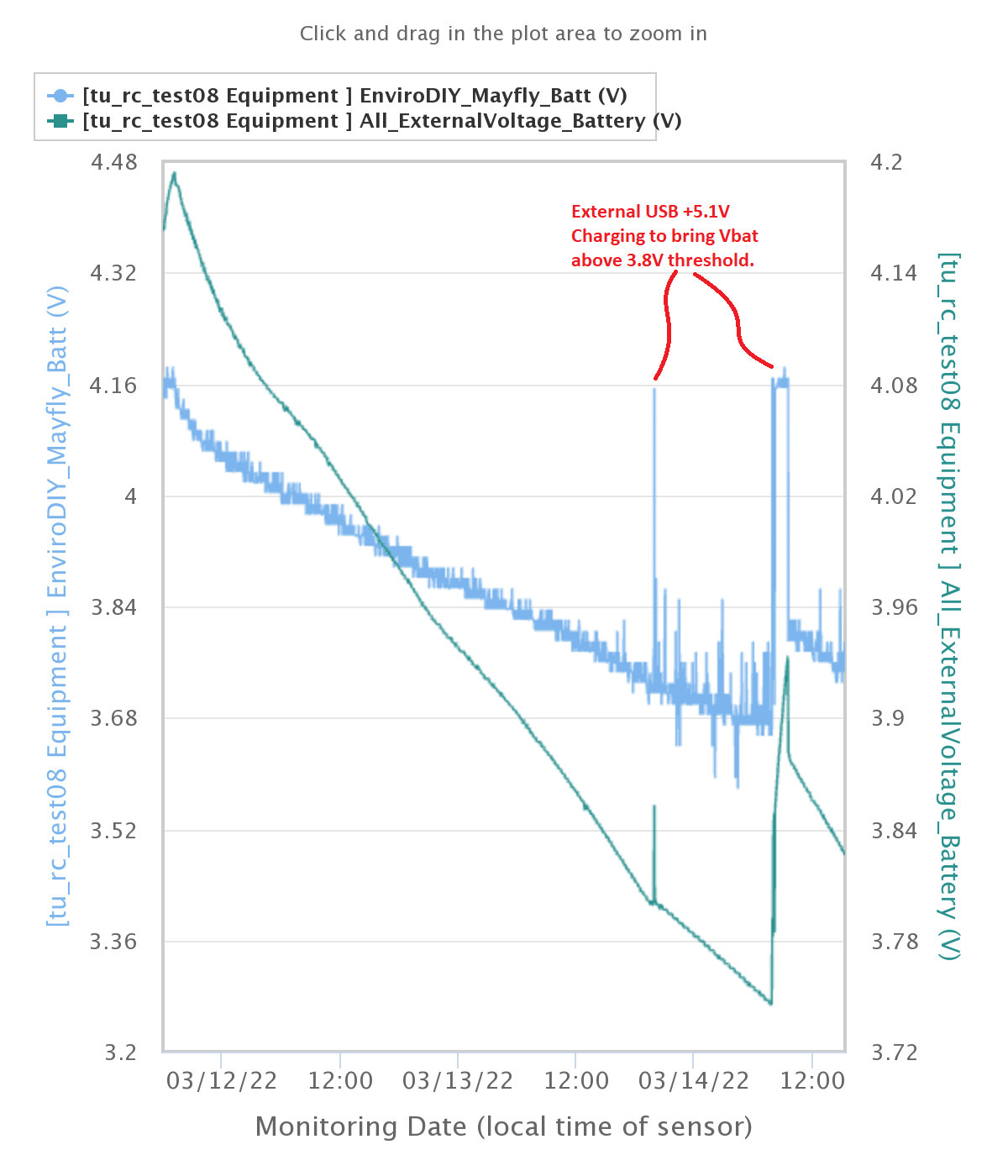
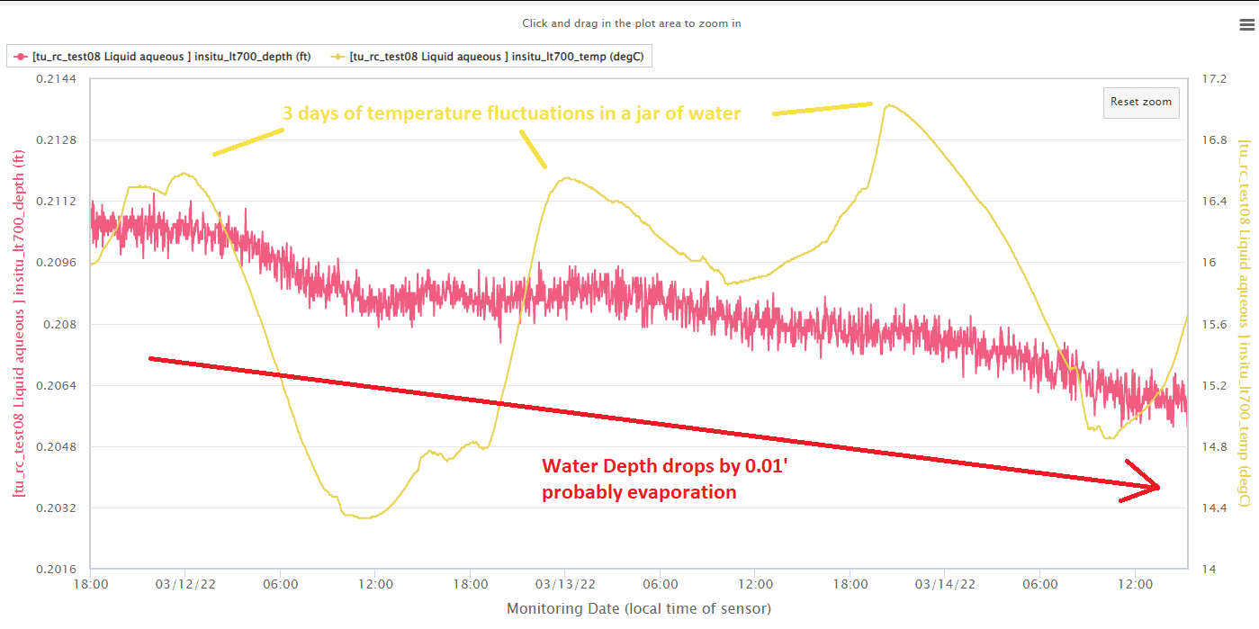
After running it over the weekend on a two minute reporting, with it sitting in a jar of water “0.21” feet deep – I have some confidence that the Modbus interface is working well. See attachment
Its also running with the new Mayfly 1.1 and using the option to SJ27 to monitor the LiPo_V – which is a new feature of the Mayfly 1.1. So while it is doing the Modbus testing, I’m taking the opportunity to regression test the battery voltage measurement issues. This is testing the Vbat to measure the LiPo V to 3.8V threshold. The BLUE line is the 10bit Mayfly 1.1 measurement voltage. The GREEN is a reliable 12bit adc source. The BLUE Vbat is still somewhat noisy jumping around. I still have an open question as to whether it can be relied on.
-
2022-03-18 at 10:08 AM #16762
Neil/Anthony,
I think we will be able to purchase one Keller CTD this year and I will work on getting it going on the Mayfly 1.1 in whatever spare time I can find in my schedule. I appreciate all the input so far and I am looking forward to digging into this in the coming months. I will keep you both posted as I get going… I’m sure there will be lots of questions. Gathering any necessary hardware will be the first step, so I will check out the RS485 driver wing board you mention above. Unfortunately, working for a government agency makes it rather impossible for me to purchase additional sensors for testing/development.
Regards,
Dan
-
2022-03-18 at 4:14 PM #16784
Great – I’ve asked https://www.instrumart.com/ if they plan on stocking it.
Something to note, a bit strange, is it comes up in SDI-12 mode, and needs an initial configuration to switch to RS485.
From getting some initial success – it may be worth starting with SDI-12 and getting some responses. Alternatively talk with a tech rep as to how they see this can be configured to RS485 before purchase.https://keller-druck.com/en/products/level-probes/multi-parameter-probes/series-36xiw-ctd
Then in the Manual https://download.keller-druck.com/api/download/yRqtkpbcVNQDHa3i7zdXDm/en/2020-04.pdf
As well as the standard RS485 interface, which provides access to
all configuration registers, the pressure level transmitter can also be
ordered with an SDI-12 interface. Only one interface will be active at
any one time. Corresponding commands are used to switch between
interfaces (default setting on delivery: SDI-12).From SDI12 manual ~ https://download.keller-druck.com/api/download/KMkeowTYmcRcUyZfadRVvZ/en/2015-11.pdf
7 Switch to RS485 (Kellerbus)
It is possible to switch from SDI-12 mode to the Kellerbus-mode (RS485 communication, Kellerbus or MODBUS RTU):
Description Command Response
Switch to RS485 (Kellerbus) aXC! aXC02Fe13! aXCD<CR><LF> (successful)
aXCE<CR><LF> (not successful)
After this command it is not possible to communicate over SDI-12 bus with the transmitter any more.
Be sure to have all hardware equipment for Kellerbus (RS485) available and the according software before switching SDI-12 off.
There is always only one communication interface active and the hardware of the other interface is switched of meanwhile and
can only be activated over a software command.
-
-
AuthorPosts

- You must be logged in to reply to this topic.