
Home › Forums › Environmental Sensors › Hydros CTD-10 Regularly Dropping Out (-9999)
- This topic has 11 replies, 5 voices, and was last updated 2022-03-09 at 2:38 PM by
 Sara Damiano.
-
AuthorPosts
-
-
2022-02-13 at 3:49 PM #16440
Hi all,
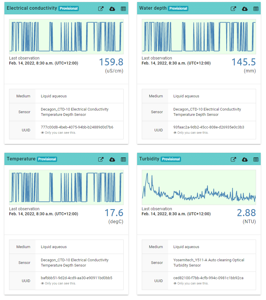
Around 50% of my sites have a problem where the CTD drops out on a regular (not predictable) basis. This results in -9999 values which may persist for a few readings before returning to normal.
I still get a data record out of this, but the resolution is lower and I would like to fix it if possible.
Has anyone experienced this before? I have tried updating the code to the complex loop (to prevent the MODBUS wing interfering with the CTD) and replacing the stereo jack adapter.
I have attached an image below, or you can see for yourself via this link:
Pongakawa Tributary at Old Coach Road (Patiki) (monitormywatershed.org)
Any help is much appreciated.
Regards,
James
Attachments:
-
2022-02-13 at 4:43 PM #16442
We’ve seen that very rarely, usually it happens when the connection between the Mayfly and the sensor is bad, and the fault is either mechanical damage to the sensor cable (rodents chewing, flood damage, etc) or corrosion on the contacts inside the Grove stereo jack due to moisture inside the logger enclosure, or bad connection of the Grove cable between the stereo board and the Mayfly. So whenever we see this sort of pattern in a CTD sensor, we replace the Grove cable and stereo jack, and 95% of the time, that solves the problem. In the rest of the cases, it’s either damage to the sensor cable or the electronics inside the sensor itself are failing (usually due to impact to the sensor body from large debris during a storm).
But if you’ve already replaced the Grove jack (and the cables?) and you’re seeing this on more than one station, then it’s likely a code or voltage issue. What version of the Mayfly board are you using (v0.5b or v1.0)? I don’t know how you’re powering the RS-485 sensors, but if they are being powered using a boost circuit that’s powered from the same voltage regulator on the Mayfly that powers everything else on the board (including the CTD sensor), then it’s possible that a voltage drop during the sampling period is causing the CTD sensor to now be fully powered, thus causing a communication issue between the Mayfly and CTD, resulting in the Mayfly reporting -9999 as the CTD sensor parameters. Have you tried just unplugging the turbidity sensor from your setup (but don’t change the logger code) and see if you’re able to get reliable communication with the CTD sensor again? If so, that would indicate the problem is related to the turbidity sensor being added. Or it could just be a software issue due to timing or other problems with the sketch. You can email me your sketch if you’d like me to take a look at it, once you’ve ruled out all the other obvious physical failures.
Other troubleshooting ideas: If you’ve got one of the ZSC bluetooth sensor interfaces from Meter Group, you could test that the sensor is operating fine independently of the Mayfly, or you could program a spare Mayfly and connect it to only the CTD sensor (first with and then without a cellular board) and have it take frequent readings (like 1 minute) and let it run for a few hours to see if it drops any readings.
-
2022-02-14 at 12:29 AM #16443
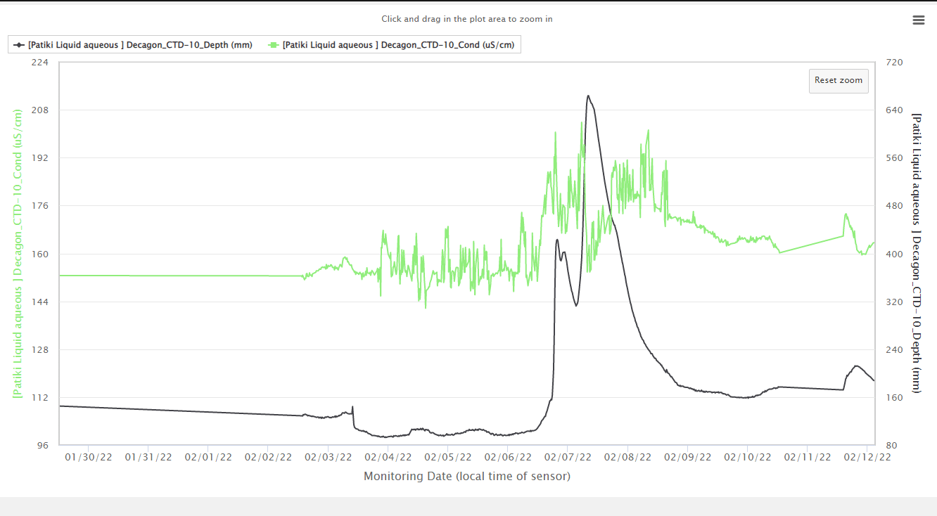
@James ouch. Looking at the data file, its just the Decagon CTD/SDI-12? readings that are responding -9999 . Typically that means the (SDI-12?) protocol has failed to communicate with the instrument.
At the same time Yosemite/Modbus? is responding well.
The CTD is only occasionally failing, or failing in groups, but still working some of the time. A hard failure where it fails all the time is easiest to debug. Intermittent failures are the hardest.
You started running the setup 2021-10-25 11:16 and
then it started failing 2021-12-09 14:45
and recovered 2021-12-14 13:00
Did you do anything to have it recover?
Since then it has intermittent failures. Ouch that is the hardest to troubleshoot.
I have one LT500 that is not working well with SDI-12, its mostly failing, but sometimes works. Similarly I purchased a device that is tested to the full SDI-12 device, and its also failing a lot. SDI-12 from the Mayfly is not a standard 0-5V, so I’m planning on moving it to the Modbus. I’m also trying to figure out a way of generating a fully specified SDI-12 0-5V
Attachments:
-
2022-02-14 at 3:19 AM #16445
I’m leaning more towards an interaction with the MODBUS wing. I had one station that produced -9999’s constantly when the Turbidity sensor was plugged in, and operated fine when I removed the MODBUS wing. This drove me nuts until Anthony pointed me towards the complex loop code where I set the Turbidity sensor to low after each reading to avoid bleeding voltage. I have subsequently uploaded the new code to all stations, which I assumed would fix the intermittent problems, but that doesn’t seem to be the case.
Other factors: there is no damage to the cables, no corrosion, and no perceivable storm damage.
Shannon, I’m using v0.5b and the sensor is powered from the grove slot (D10/D11). I changed the voltage jumper to 5v because 3.3v was resulting in -9999 values (I assume because of brownout?).
I haven’t tried unplugging the MODBUS wing, but I bet the CTD record would be perfect if I did. I can test this later this week if we don’t find another solution.
Perhaps it’s my code (see below)? Can either of you see any obvious errors?
Thanks for your help.
James
C++123456789101112131415161718192021222324252627282930313233343536373839404142434445464748495051525354555657585960616263646566676869707172737475767778798081828384858687888990919293949596979899100101102103104105106107108109110111112113114115116117118119120121122123124125126127128129130131132133134135136137138139140141142143144145146147148149150151152153154155156157158159160161162163164165166167168169170171172173174175176177178179180181182183184185186187188189190191192193194195196197198199200201202203204205206207208209210211212213214215216217218219220221222223224225226227228229230231232233234235236237238239240241242243244245246247248249250251252253254255256257258259260261262263264265266267268269270271272273274275276277278279280281282283284285286287288289290291292293294295296297298299300301302303304305306307308309310311312313314315316317318319320321322323324325326327328329330331332333334335336337338339340341342343344345346347348349350351352353354355356357358359360361362363364365366367368369370371372373374375376377378379380381382383384385386387388389390391392393394395396397398399400401402403404405406407408409410411412413414415416417418419420421422423424425426427428429430431432433434435436437438439440441442443444445446447448449450451452453454455456457458459460461462463464465466467468469470471472473474475476477478479480481482483484485486487488489490491492493494495496497498499500501502503504505506507508509510511512513514515516517518519520521522523524525526527528529530531532533534535536537538539540541542543544545546/*****************************************************************************simple_logging.inoWritten By: Sara Damiano (sdamiano@stroudcenter.org)Development Environment: PlatformIOHardware Platform: EnviroDIY Mayfly Arduino DataloggerSoftware License: BSD-3.Copyright (c) 2017, Stroud Water Research Center (SWRC)and the EnviroDIY Development TeamThis sketch is an example of logging data to an SD cardDISCLAIMER:THIS CODE IS PROVIDED "AS IS" - NO WARRANTY IS GIVEN.*****************************************************************************/// ==========================================================================// Defines for the Arduino IDE// In PlatformIO, set these build flags in your platformio.ini// ==========================================================================#ifndef TINY_GSM_RX_BUFFER#define TINY_GSM_RX_BUFFER 64#endif#ifndef TINY_GSM_YIELD_MS#define TINY_GSM_YIELD_MS 2#endif#ifndef MQTT_MAX_PACKET_SIZE#define MQTT_MAX_PACKET_SIZE 240#endif// ==========================================================================// Include the base required libraries// ==========================================================================#include <Arduino.h> // The base Arduino library#include <EnableInterrupt.h> // for external and pin change interrupts#include <LoggerBase.h> // The modular sensors library//#include <Adafruit_ADS1015.h>//Adafruit_ADS1115 ads; /* Use this for the Mayfly because of the onboard 16-bit ADS1115 *///#include <AltSoftSerial.h>//#include <YosemitechModbus.h>// ==========================================================================// Data Logger Settings// ==========================================================================// The name of this fileconst char *sketchName = "05_Patiki.ino";// Logger ID, also becomes the prefix for the name of the data file on SD cardconst char *LoggerID = "Patiki";// How frequently (in minutes) to log dataconst uint8_t loggingInterval = 15;// Your logger's timezone.const int8_t timeZone = 12; // Eastern Standard Time// NOTE: Daylight savings time will not be applied! Please use standard time!// ==========================================================================// Primary Arduino-Based Board and Processor// ==========================================================================#include <sensors/ProcessorStats.h>const long serialBaud = 115200; // Baud rate for the primary serial port for debuggingconst int8_t greenLED = 8; // MCU pin for the green LED (-1 if not applicable)const int8_t redLED = 9; // MCU pin for the red LED (-1 if not applicable)const int8_t buttonPin = 21; // MCU pin for a button to use to enter debugging mode (-1 if not applicable)const int8_t wakePin = A7; // MCU interrupt/alarm pin to wake from sleep// Set the wake pin to -1 if you do not want the main processor to sleep.// In a SAMD system where you are using the built-in rtc, set wakePin to 1const int8_t sdCardPwrPin = -1; // MCU SD card power pin (-1 if not applicable)const int8_t sdCardSSPin = 12; // MCU SD card chip select/slave select pin (must be given!)const int8_t sensorPowerPin = 22; // MCU pin controlling main sensor power (-1 if not applicable)// Create the main processor chip "sensor" - for general metadataconst char *mcuBoardVersion = "v0.5b";ProcessorStats mcuBoard(mcuBoardVersion);// ==========================================================================// Wifi/Cellular Modem Settings// ==========================================================================// Create a reference to the serial port for the modemHardwareSerial &modemSerial = Serial1; // Use hardware serial if possible// Modem Pins - Describe the physical pin connection of your modem to your boardconst int8_t modemVccPin = -1; // MCU pin controlling modem power (-1 if not applicable)//const bool useCTSforStatus = false; // Flag to use the XBee CTS pin for statusconst int8_t modemStatusPin = 19; // MCU pin used to read modem status (-1 if not applicable)const int8_t modemResetPin = 20; // MCU pin connected to modem reset pin (-1 if unconnected)const int8_t modemSleepRqPin = 23; // MCU pin used for modem sleep/wake request (-1 if not applicable)const int8_t modemLEDPin = redLED; // MCU pin connected an LED to show modem status (-1 if unconnected)// // Network connection information// Network connection informationconst char *apn = "m2m"; // The APN for the gprs connection// const char *wifiId = "Dare_Family"; // The WiFi access point, unnecessary for gprs// const char *wifiPwd = "119HarveyStreet"; // The password for connecting to WiFi, unnecessary for gprs// ==========================================================================// The modem object// Note: Don't use more than one!// ==========================================================================//#elif defined MS_BUILD_TESTING && defined MS_BUILD_TEST_XBEE_LTE_B// For the u-blox SARA R410M based Digi LTE-M XBee3// NOTE: According to the manual, this should be less stable than transparent// mode, but my experience is the complete reverse.#include <modems/DigiXBeeLTEBypass.h>//#include <modems/SodaqDigiXBeeLTEBypass.h>const long modemBaud = 9600; // All XBee's use 9600 by defaultconst bool useCTSforStatus = false; // Flag to use the XBee CTS pin for status// NOTE: If possible, use the STATUS/SLEEP_not (XBee pin 13) for status, but// the CTS pin can also be used if necessaryDigiXBeeLTEBypass modemXBLTEB(&modemSerial,modemVccPin, modemStatusPin, useCTSforStatus,modemResetPin, modemSleepRqPin,apn);// Create an extra reference to the modem by a generic name (not necessary)DigiXBeeLTEBypass modem = modemXBLTEB;// ==========================================================================// ==========================================================================// Maxim DS3231 RTC (Real Time Clock)// ==========================================================================#include <sensors/MaximDS3231.h> // Includes wrapper functions for Maxim DS3231 RTC// Create a DS3231 sensor object, using this constructor function:MaximDS3231 ds3231(1);// ==========================================================================// Meter Hydros 21 Conductivity, Temperature, and Depth Sensor// ==========================================================================/** Start [hydros21] */#include <sensors/DecagonCTD.h>const char* CTDSDI12address = "1"; // The SDI-12 Address of the CTDconst uint8_t CTDNumberReadings = 6; // The number of readings to averageconst int8_t CTDPower = sensorPowerPin; // Power pin (-1 if unconnected)const int8_t CTDData = 11; // The SDI12 data pin// Create a Decagon CTD sensor objectDecagonCTD ctd(*CTDSDI12address, CTDPower, CTDData, CTDNumberReadings);// Create conductivity, temperature, and depth variable pointers for the CTD//Variable* ctdCond = new DecagonCTD_Cond(&ctd,// "12345678-abcd-1234-ef00-1234567890ab");//Variable* ctdTemp = new DecagonCTD_Temp(&ctd,// "12345678-abcd-1234-ef00-1234567890ab");//Variable* ctdDepth =// new DecagonCTD_Depth(&ctd, "12345678-abcd-1234-ef00-1234567890ab");/** End [hydros21] */// ==========================================================================// Yosemitech Y511 Turbidity Sensor with Wiper// ==========================================================================/** Start [y511] */#include <sensors/YosemitechY511.h>#include <AltSoftSerial.h>AltSoftSerial altSoftSerial;// Create a reference to the serial port for modbus// Extra hardware and software serial ports are created in the "Settings for// Additional Serial Ports" section#if defined ARDUINO_ARCH_SAMD || defined ATMEGA2560HardwareSerial& y511modbusSerial = Serial2; // Use hardware serial if possible#elseAltSoftSerial& y511modbusSerial = altSoftSerial; // For software serial// NeoSWSerial& y511modbusSerial = neoSSerial1; // For software serial#endifbyte y511ModbusAddress = 0x01; // The modbus address of the Y511const int8_t y511AdapterPower =sensorPowerPin; // RS485 adapter power pin (-1 if unconnected)const int8_t y511SensorPower = -1; // Sensor power pinconst int8_t y511EnablePin = -1; // Adapter RE/DE pin (-1 if not applicable)const uint8_t y511NumberReadings = 5;// The manufacturer recommends averaging 10 readings, but we take 5 to minimize// power consumption// Create a Y511-A Turbidity sensor objectYosemitechY511 y511(y511ModbusAddress, y511modbusSerial, y511AdapterPower,y511SensorPower, y511EnablePin, y511NumberReadings);// Create turbidity and temperature variable pointers for the Y511//Variable* y511Turb =// new YosemitechY511_Turbidity(&y511, "12345678-abcd-1234-ef00-1234567890ab");//Variable* y511Temp =// new YosemitechY511_Temp(&y511, "12345678-abcd-1234-ef00-1234567890ab");/** End [y511] */// ==========================================================================// Creating the Variable Array[s] and Filling with Variable Objects// ==========================================================================Variable *variableList[] = {//new ProcessorStats_SampleNumber(&mcuBoard),//new ProcessorStats_FreeRam(&mcuBoard),new ProcessorStats_Battery(&mcuBoard,"03c5abcd-dfd6-4c58-b028-5cf6e2c95d57"),new MaximDS3231_Temp(&ds3231,"1cd4ab1f-507a-4072-a8dc-e2927658f59e"),new DecagonCTD_Cond(&ctd, "777c00d8-4beb-4075-94bb-b24889d0d7b6"),new DecagonCTD_Temp(&ctd, "bafbbb51-9d2d-4cd9-aa30-e90911bd0bb5"),new DecagonCTD_Depth(&ctd, "93faac2a-9db2-45cc-808e-d26935e0c3b3"),new YosemitechY511_Turbidity(&y511, "ced82100-f7bb-4cfb-994c-0981c1bb92ca"),new YosemitechY511_Temp(&y511, "833d69ef-c52f-4480-8e80-151322fb8532")// Additional sensor variables can be added here, by copying the syntax// for creating the variable pointer (FORM1) from the <code>menu_a_la_carte.ino</code> example// The example code snippets in the wiki are primarily FORM2.};// Count up the number of pointers in the arrayint variableCount = sizeof(variableList) / sizeof(variableList[0]);// Create the VariableArray objectVariableArray varArray(variableCount, variableList);// ==========================================================================// The Logger Object[s]// ==========================================================================// Create a logger instanceLogger dataLogger(LoggerID, loggingInterval, &varArray);// ==========================================================================// A Publisher to Monitor My Watershed / EnviroDIY Data Sharing Portal// ==========================================================================// Device registration and sampling feature information can be obtained after// registration at https://monitormywatershed.org or https://data.envirodiy.orgconst char *registrationToken = "9ce32f4c-faeb-4657-8fdb-31c515b66348"; // Device registration tokenconst char *samplingFeature = "65c04ec5-acd2-46fa-8c09-3a1ebd05672f"; // Sampling feature UUID// const char *UUIDs[] = // UUID array for device sensors// {// "0bc19c50-67d8-4012-9e17-fb32db82f1ca", // Temperature (Maxim_DS18B20_Temp)// "846f84dc-4455-47f3-bd38-51a21e20fa50" // Temperature (Maxim_DS3231_Temp)// };// Create a data publisher for the EnviroDIY/WikiWatershed POST endpoint#include <publishers/EnviroDIYPublisher.h>EnviroDIYPublisher EnviroDIYPOST(dataLogger, &modem.gsmClient, registrationToken, samplingFeature);// ==========================================================================// Working Functions// ==========================================================================// Flashes the LED's on the primary boardvoid greenredflash(uint8_t numFlash = 4, uint8_t rate = 75){for (uint8_t i = 0; i < numFlash; i++) {digitalWrite(greenLED, HIGH);digitalWrite(redLED, LOW);delay(rate);digitalWrite(greenLED, LOW);digitalWrite(redLED, HIGH);delay(rate);}digitalWrite(redLED, LOW);}// Read's the battery voltage// NOTE: This will actually return the battery level from the previous update!float getBatteryVoltage(){if (mcuBoard.sensorValues[0] == -9999) mcuBoard.update();return mcuBoard.sensorValues[0];}//Median Funtion// calculate a median for set of values in bufferint getMedianNum(int bArray[], int iFilterLen){ int bTab[iFilterLen];for (byte i = 0; i<iFilterLen; i++)bTab[i] = bArray[i]; // copy input array into BTab[] arrayint i, j, bTemp;for (j = 0; j < iFilterLen - 1; j++) // put array in ascending order{ for (i = 0; i < iFilterLen - j - 1; i++){ if (bTab[i] > bTab[i + 1]){ bTemp = bTab[i];bTab[i] = bTab[i + 1];bTab[i + 1] = bTemp;}}}if ((iFilterLen & 1) > 0) // check to see if iFilterlen is odd or even using & (bitwise AND) i.e if length &AND 1 is TRUE (>0)bTemp = bTab[(iFilterLen - 1) / 2]; // then then it is odd, and should take the central valueelsebTemp = (bTab[iFilterLen / 2] + bTab[iFilterLen / 2 - 1]) / 2; // if even then take aveage of two central valuesreturn bTemp;} //end getmedianNum// ==========================================================================// Main setup function// ==========================================================================void setup(){// Wait for USB connection to be established by PC// NOTE: Only use this when debugging - if not connected to a PC, this// could prevent the script from starting#if defined SERIAL_PORT_USBVIRTUALwhile (!SERIAL_PORT_USBVIRTUAL && (millis() < 10000)){}#endif// Start the primary serial connectionSerial.begin(serialBaud);// Print a start-up note to the first serial portSerial.print(F("Now running "));Serial.print(sketchName);Serial.print(F(" on Logger "));Serial.println(LoggerID);Serial.println();Serial.print(F("Using ModularSensors Library version "));Serial.println(MODULAR_SENSORS_VERSION);Serial.print(F("TinyGSM Library version "));Serial.println(TINYGSM_VERSION);Serial.println();// Allow interrupts for software serial#if defined SoftwareSerial_ExtInts_henableInterrupt(softSerialRx, SoftwareSerial_ExtInts::handle_interrupt, CHANGE);#endif#if defined NeoSWSerial_henableInterrupt(neoSSerial1Rx, neoSSerial1ISR, CHANGE);#endif// Start the serial connection with the modemmodemSerial.begin(modemBaud);// Start the stream for the modbus sensors; all currently supported modbus sensors use 9600 baudy511modbusSerial.begin(9600);// Set up pins for the LED'spinMode(greenLED, OUTPUT);digitalWrite(greenLED, LOW);pinMode(redLED, OUTPUT);digitalWrite(redLED, LOW);// Blink the LEDs to show the board is on and starting upgreenredflash();// Set the timezones for the logger/data and the RTC// Logging in the given time zoneLogger::setLoggerTimeZone(timeZone);// It is STRONGLY RECOMMENDED that you set the RTC to be in UTC (UTC+0)Logger::setRTCTimeZone(0);// Attach the modem and information pins to the loggerdataLogger.attachModem(modem);modem.setModemLED(modemLEDPin);dataLogger.setLoggerPins(wakePin, sdCardSSPin, sdCardPwrPin, buttonPin, greenLED);// Begin the loggerdataLogger.begin();// Note: Please change these battery voltages to match your battery// Set up the sensors, except at lowest battery levelif (getBatteryVoltage() > 3.4){Serial.println(F("Setting up sensors..."));varArray.setupSensors();}// Sync the clock if it isn't valid or we have battery to spareif (getBatteryVoltage() > 3.55 || !dataLogger.isRTCSane()){// Synchronize the RTC with NIST// This will also set up the modemdataLogger.syncRTC();}// Create the log file, adding the default header to it// Do this last so we have the best chance of getting the time correct and// all sensor names correct// Writing to the SD card can be power intensive, so if we're skipping// the sensor setup we'll skip this too.if (getBatteryVoltage() > 3.4){Serial.println(F("Setting up file on SD card"));dataLogger.turnOnSDcard(true); // true = wait for card to settle after power updataLogger.createLogFile(true); // true = write a new headerdataLogger.turnOffSDcard(true); // true = wait for internal housekeeping after write}// Set up some of the power pins so the board boots up with them off// NOTE: This isn't necessary at all. The logger begin() function// should leave all power pins off when it finishes.if (modemVccPin >= 0){pinMode(modemVccPin, OUTPUT);digitalWrite(modemVccPin, LOW);pinMode(modemSleepRqPin, OUTPUT); // <- AddeddigitalWrite(modemSleepRqPin, HIGH); // <- Added}// Call the processor sleepSerial.println(F("Putting processor to sleep\n"));dataLogger.systemSleep();}// ==========================================================================// Main loop function// ==========================================================================/** Start [complex_loop] */// Use this long loop when you want to do something special// Because of the way alarms work on the RTC, it will wake the processor and// start the loop every minute exactly on the minute.// The processor may also be woken up by another interrupt or level change on a// pin - from a button or some other input.// The "if" statements in the loop determine what will happen - whether the// sensors update, testing mode starts, or it goes back to sleep.void loop() {// Reset the watchdogdataLogger.watchDogTimer.resetWatchDog();// Assuming we were woken up by the clock, check if the current time is an// even interval of the logging interval// We're only doing anything at all if the battery is above 3.4Vif (dataLogger.checkInterval() && getBatteryVoltage() > 3.4) {// Flag to notify that we're in already awake and logging a pointLogger::isLoggingNow = true;dataLogger.watchDogTimer.resetWatchDog();// Print a line to show new readingSerial.println(F("------------------------------------------"));// Turn on the LED to show we're taking a readingdataLogger.alertOn();// Power up the SD Card, but skip any waits after power updataLogger.turnOnSDcard(false);dataLogger.watchDogTimer.resetWatchDog();// Turn on the modem to let it start searching for the network// Only turn the modem on if the battery at the last interval was high// enough// NOTE: if the modemPowerUp function is not run before the// completeUpdate// function is run, the modem will not be powered and will not// return a signal strength reading.if (getBatteryVoltage() > 3.6) modem.modemPowerUp();// Start the stream for the modbus sensors, if your RS485 adapter bleeds// current from data pins when powered off & you stop modbus serial// connection with digitalWrite(5, LOW), below.// https://github.com/EnviroDIY/ModularSensors/issues/140#issuecomment-389380833altSoftSerial.begin(9600);// Do a complete update on the variable array.// This this includes powering all of the sensors, getting updated// values, and turing them back off.// NOTE: The wake function for each sensor should force sensor setup// to run if the sensor was not previously set up.varArray.completeUpdate();dataLogger.watchDogTimer.resetWatchDog();// Reset modbus serial pins to LOW, if your RS485 adapter bleeds power// on sleep, because Modbus Stop bit leaves these pins HIGH.// https://github.com/EnviroDIY/ModularSensors/issues/140#issuecomment-389380833digitalWrite(5, LOW); // Reset AltSoftSerial Tx pin to LOWdigitalWrite(6, LOW); // Reset AltSoftSerial Rx pin to LOW// Create a csv data record and save it to the log filedataLogger.logToSD();dataLogger.watchDogTimer.resetWatchDog();// Connect to the network// Again, we're only doing this if the battery is doing wellif (getBatteryVoltage() > 3.55) {//Serial.println(F("Waking up modem-------"));//Serial.println(F("Waking up") + modem.getModemName() + F("..."));modem.modemWake();dataLogger.watchDogTimer.resetWatchDog();if (modem.connectInternet()) {dataLogger.watchDogTimer.resetWatchDog();// Publish data to remotesSerial.println(F("Modem connected to internet."));dataLogger.publishDataToRemotes();// Sync the clock at midnightdataLogger.watchDogTimer.resetWatchDog();if (Logger::markedEpochTime != 0 &&Logger::markedEpochTime % 86400 == 0) {Serial.println(F("Running a daily clock sync..."));dataLogger.setRTClock(modem.getNISTTime());dataLogger.watchDogTimer.resetWatchDog();modem.updateModemMetadata();dataLogger.watchDogTimer.resetWatchDog();}// Disconnect from the networkmodem.disconnectInternet();dataLogger.watchDogTimer.resetWatchDog();}// Turn the modem offmodem.modemSleepPowerDown();dataLogger.watchDogTimer.resetWatchDog();}// Cut power from the SD card - without additional housekeeping waitdataLogger.turnOffSDcard(false);dataLogger.watchDogTimer.resetWatchDog();// Turn off the LEDdataLogger.alertOff();// Print a line to show reading endedSerial.println(F("------------------------------------------\n"));// Unset flagLogger::isLoggingNow = false;}// Check if it was instead the testing interrupt that woke us upif (Logger::startTesting) {// Start the stream for the modbus sensors, if your RS485 adapter bleeds// current from data pins when powered off & you stop modbus serial// connection with digitalWrite(5, LOW), below.// https://github.com/EnviroDIY/ModularSensors/issues/140#issuecomment-389380833altSoftSerial.begin(9600);dataLogger.testingMode();}// Reset modbus serial pins to LOW, if your RS485 adapter bleeds power// on sleep, because Modbus Stop bit leaves these pins HIGH.// https://github.com/EnviroDIY/ModularSensors/issues/140#issuecomment-389380833digitalWrite(5, LOW); // Reset AltSoftSerial Tx pin to LOWdigitalWrite(6, LOW); // Reset AltSoftSerial Rx pin to LOW// Call the processor sleepdataLogger.systemSleep();} -
2022-02-15 at 10:05 PM #16482
-
2022-02-15 at 10:07 PM #16483
I’m not familiar with the code regarding the complex loop since it’s not something I’ve ever used, and I’ve also not used one of those modbus wings, so I think Anthony or Neil will need to be the ones to help with this issue.
-
2022-02-16 at 1:19 AM #16484
@James_NZ – are all your setups the same?.
Have you got a spare setup that can be debugged in a local setting? (office with terminal connected)
I have a similar setup with an RS485 and SDI-12 on one system – but I maintain a test system to verify it before I deploy it.
https://monitormywatershed.org/sites/TUCA-Na13/
I have done work to ruggedize it. All I can do is describe how I do it.
-
2022-02-16 at 2:24 PM #16497
@shicks, thanks for your help anyway Shannon. @aufdenkampe, any insight on the code above would be greatly appreciated.
@neilh20, yes all setups are the same. Some work fine, others have issues with dropping out. I have spare Mayflies and a spare CTD, but no spare turbidity sensor. Did you ever end up producing your Mayfly wings for the 0.5? This might just be another case of rubbish RS485/ttl’s.I kinda wish my project was delayed by six months so I could get the version 1.0’s with the new modbus wing!
James
-
2022-02-16 at 6:58 PM #16498
@james_nz my process is to stage systems in an accessible context to check the reliability of the systems. This comes from the school of hard knocks working with embedded processors like the Mayfly.
IMHO while ModularSensors software has some fantastic classes to be able to access the instruments and also to push to cloud locations, Arduino Open Source is generally at the level of – Arduino teaching ~ this is how it can be done.
Its next to impossible to teach “reliability” – its usually learnt through being on the “bleeding edge”. The 2nd time around one tends to add more foundational capability to better cope with reliability testing.
You reference “dropping out” which can be a whole record or one instrument. A record lost is typically due to “internet failure”, but still stored on the uSD.
Individual readings, usually digital instrument, when the digital comms link to the digital instrument fails.
It seems, for the above referenced node, your RS485 instruments are responding OK, its the SDI-12 instruments that are having comms failures.
Its should be noted that the Mayfly’s xx could be said to support “Arduino SDI-12”, that is they show how it can be done, but there is a lot of technical debt. It isn’t per the SDI-12.org specification for signaling and protection.
I’ve been trying to prototype a solution to this for some time. Right now my RS485board includes SDI-12 protection and level shift. However I still need to work on the SDI-12 software for it to cope with the level shift. https://www.envirodiy.org/topic/sdi-12-level-shifting/
Currently when you access the Mayfly X with the USB cable (or even the FTDI cable), it causes the Mayfly to reset – a nice Arduino feature of always making sure the board can be programmed. However that reset isn’t good for reliability monitoring – that is plugging in and just monitoring how its been working – I’ve created a modified FTDI connector to allow that https://github.com/neilh10/ModularSensors/wiki/Test-Equipment-FTDI-cable
-
2022-03-01 at 7:14 PM #16651
Hi James, we regularly had this problem when using the Decagon CTD-10s connected to a DIY Arduino Mega data logger. We ended up taking the median value of 10 measurements taken 1x/second every 5 mins. However, what eventually worked (if I’m remembering this correctly; this was my dissertation research done in 2016-2019) was clamping an RF ferrite balun filter to the cables. They looked something like this: https://www.digikey.com/en/products/detail/fair-rite-products-corp./0444173951/8594098?utm_adgroup=Ferrite%20Cores%20-%20Cables%20and%20Wiring&utm_source=google&utm_medium=cpc&utm_campaign=Shopping_Product_Filters_NEW&utm_term=&utm_content=Ferrite%20Cores%20-%20Cables%20and%20Wiring&gclid=CjwKCAiApfeQBhAUEiwA7K_UH7XcVuubBeU3WlGAQFSizFtYSRyiAbgXnIgNb0TLWobKsUVKiNRBVxoCfTAQAvD_BwE
I think it must’ve been noise interference from somewhere on our board. Hope this helps! I have code you’re welcome too if you’re interested.
Stephanie
-
2022-03-03 at 9:19 PM #16666
-
2022-03-09 at 2:38 PM #16689
If the communication works sporadically, it’s more likely to be an electrical issue than a code issue. Coding issues *usually* cause it to not work at all.
The -9999 is the library’s value for a failed reading. When you get in in SDI-12, it most often means the sensor didn’t respond or the response was garbled. Because the Mayfly’s voltage (and thus serial communication) range is only 3.3V, it doesn’t take much electrical noise to garble things up.
-
-
AuthorPosts
- You must be logged in to reply to this topic.