Home › Forums › Mayfly Data Logger › Why is 12V power on Mayfly V1.1 (rev A) nominally only 11.3V? › Reply To: Why is 12V power on Mayfly V1.1 (rev A) nominally only 11.3V?
Mayfly v1.0RevA had a Max17250 boost chip that used the following resistors in order to set the output voltage at 12 volts:
R15 = 10k
R19 = 84.5k
R31 = 220k
When it was time to manufacture more boards in 2021, there was a semiconductor shortage that made it impossible to find that particular boost converter, so the design was modified to use a MCP1665 instead. However, the first small run of Mayfly v1.1RevA boards used the resistors above from the previous circuit instead of the correct values below:
R15 = 20k
R19 = 180k
R31 = 470k
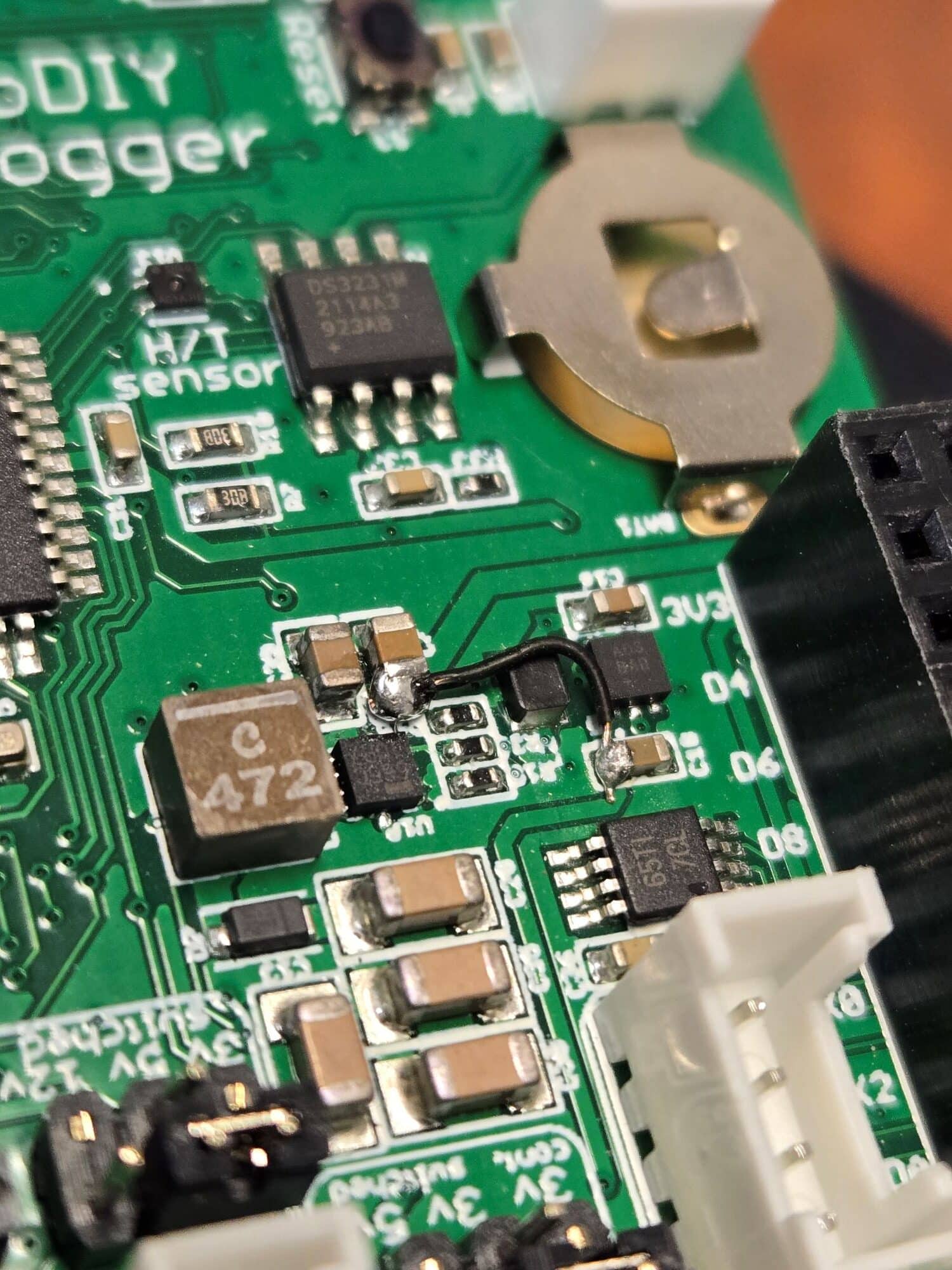
The input power selection options for the MCP1665 also didn’t behave like the Max17350 did, so before we shipped out any Mayfly boards from that run, I put a blob of silicone conformal coating on the back of the boards to cover SJ26 to make it unusable and also made a note about it on the schematic. I also manually soldered a tiny black wire onto each board to connect the power circuit properly, as denoted by the blue line in the schematic and shown in the attached photo below.
So when it came time for the next production run, we opted to call it v1.1RevB since it would correct the problem with the incorrect resistors, add a trace to connect power circuits properly (to take the place of the black wire), and remove solder jumper SJ26 from the back of the board since it was no longer needed. We also switched the ICSP connector from a small 2×3 0.5mm pitch header to a Tac-connect connector.
Someone asked this question about version differences a few years ago on the Technical Questions thread, and you can see my specific response here.
So in summary, the schematic currently on the website for v1.1RevA was what we designed, however the 3 resistor values placed by the manufacturer are different than specified in the documentation. This affected only a small number of boards because we quickly made a new production run for v1.1RevB. However not all of the documentation in various locations got updated with the latest specs. I’ll go back and add a note to the v1.1RevA schematic to clarify which resistors were actually used on that batch, and will also update the Details and Specs page to more clearly state the specs of the current v1.1RevB board.