@jsterlingchattahoochee-org
Active 1 year, 2 months agoForum Replies Created
-
AuthorPosts
-
I uploaded the “SDI12/b_address_change” sketch and the address of the sensor is correctly assigned at “2”. My sketch is below. I modified the DWRI CitSci code for the ClariVUE. Thanks for taking a look!
Arduino123456789101112131415161718192021222324252627282930313233343536373839404142434445464748495051525354555657585960616263646566676869707172737475767778798081828384858687888990919293949596979899100101102103104105106107108109110111112113114115116117118119120121122123124125126127128129130131132133134135136137138139140141142143144145146147148149150151152153154155156157158159160161162163164165166167168169170171172173174175176177178179180181182183184185186187188189190191192193194195196197198199200201202203204205206207208209210211212213214215216217218219220221222223224225226227228229230231232233234235236237238239240241242243244245246247248249250251252253254255256257258259260261262263264265266267268269270271272273274275276277278279280281282283284285286287288289290291292293294295296297298299300301302303304305306307308309310311312313314315316317318319320321322323324325326327328329330331332333334335336337338339340341342343344345346347348349350351352353354355356357358359360361362363364365366367368369370371372373374375376377378379380381382383384385386387388389390391392393394395/** =========================================================================* @file DRWI_SIM7080LTE.ino* @brief Example for DRWI CitSci LTE sites.** This example shows proper settings for the following configuration:** Mayfly v1.1 board* EnviroDIY SIM7080 LTE module (with Hologram SIM card)* ES2 sensor* Campbell Scientific ClareVUE10 Turbidity sensor** @author Sara Geleskie Damiano <sdamiano@stroudcenter.org>* @copyright (c) 2017-2022 Stroud Water Research Center (SWRC)* and the EnviroDIY Development Team* This example is published under the BSD-3 license.** Hardware Platform: EnviroDIY Mayfly Arduino Datalogger** DISCLAIMER:* THIS CODE IS PROVIDED "AS IS" - NO WARRANTY IS GIVEN.** CASSI 6 version 2* ======================================================================= */// ==========================================================================// Defines for the Arduino IDE// NOTE: These are ONLY needed to compile with the Arduino IDE.// If you use PlatformIO, you should set these build flags in your// platformio.ini// ==========================================================================/** Start [defines] */#ifndef TINY_GSM_RX_BUFFER#define TINY_GSM_RX_BUFFER 64#endif#ifndef TINY_GSM_YIELD_MS#define TINY_GSM_YIELD_MS 2#endif/** End [defines] */// ==========================================================================// Include the libraries required for any data logger// ==========================================================================/** Start [includes] */// The Arduino library is needed for every Arduino program.#include <Arduino.h>// EnableInterrupt is used by ModularSensors for external and pin change// interrupts and must be explicitly included in the main program.#include <EnableInterrupt.h>// Include the main header for ModularSensors#include <ModularSensors.h>/** End [includes] */// ==========================================================================// Data Logging Options// ==========================================================================/** Start [logging_options] */// The name of this program fileconst char* sketchName = "CASSI6.ino";// Logger ID, also becomes the prefix for the name of the data file on SD cardconst char* LoggerID = "CASSI6";// How frequently (in minutes) to log dataconst uint8_t loggingInterval = 3;// Your logger's timezone.const int8_t timeZone = -5; // Eastern Standard Time// NOTE: Daylight savings time will not be applied! Please use standard time!// Set the input and output pins for the logger// NOTE: Use -1 for pins that do not applyconst int32_t serialBaud = 57600; // Baud rate for debuggingconst int8_t greenLED = 8; // Pin for the green LEDconst int8_t redLED = 9; // Pin for the red LEDconst int8_t buttonPin = 21; // Pin for debugging mode (ie, button pin)const int8_t wakePin = 31; // MCU interrupt/alarm pin to wake from sleep// Mayfly 0.x D31 = A7const int8_t sdCardPwrPin = -1; // MCU SD card power pinconst int8_t sdCardSSPin = 12; // SD card chip select/slave select pinconst int8_t sensorPowerPin = 22; // MCU pin controlling main sensor power/** End [logging_options] */// ==========================================================================// Wifi/Cellular Modem Options// ==========================================================================/** Start [sim_com_sim7080] */// For almost anything based on the SIMCom SIM7080G#include <modems/SIMComSIM7080.h>// Create a reference to the serial port for the modemHardwareSerial& modemSerial = Serial1; // Use hardware serial if possibleconst int32_t modemBaud = 9600; // SIM7080 does auto-bauding by default, but// for simplicity we set to 9600// Modem Pins - Describe the physical pin connection of your modem to your board// NOTE: Use -1 for pins that do not applyconst int8_t modemVccPin = 18;// MCU pin controlling modem power --- Pin 18 is the power enable pin for the// bee socket on Mayfly v1.0, use -1 if using Mayfly 0.5b or if the bee socket// is constantly powered (ie you changed SJ18 on Mayfly 1.x to 3.3v)const int8_t modemStatusPin = 19; // MCU pin used to read modem statusconst int8_t modemSleepRqPin = 23; // MCU pin for modem sleep/wake requestconst int8_t modemLEDPin = redLED; // MCU pin connected an LED to show modem// status// Network connection informationconst char* apn ="hologram"; // APN connection name, typically Hologram unless you have a// different provider's SIM card. Change as needed// Create the modem objectSIMComSIM7080 modem7080(&modemSerial, modemVccPin, modemStatusPin,modemSleepRqPin, apn);// Create an extra reference to the modem by a generic nameSIMComSIM7080 modem = modem7080;/** End [sim_com_sim7080] */// ==========================================================================// Using the Processor as a Sensor// ==========================================================================/** Start [processor_sensor] */#include <sensors/ProcessorStats.h>// Create the main processor chip "sensor" - for general metadataconst char* mcuBoardVersion = "v1.1";ProcessorStats mcuBoard(mcuBoardVersion);/** End [processor_sensor] */// ==========================================================================// Maxim DS3231 RTC (Real Time Clock)// ==========================================================================/** Start [ds3231] */#include <sensors/MaximDS3231.h>// Create a DS3231 sensor objectMaximDS3231 ds3231(1);/** End [ds3231] *///\// ==========================================================================// Decagon ES2 Conductivity and Temperature Sensor// ==========================================================================/** Start [es2] */#include <sensors/DecagonES2.h>// NOTE: Use -1 for any pins that don't apply or aren't being used.const char* ES2SDI12address = "1"; // The SDI-12 Address of the ES2const int8_t ES2Power = sensorPowerPin; // Power pinconst int8_t ES2Data = 7; // The SDI12 data pinconst uint8_t ES2NumberReadings = 5;// Create a Decagon ES2 sensor objectDecagonES2 es2(*ES2SDI12address, ES2Power, ES2Data, ES2NumberReadings);\/** End [es2] */\// ==========================================================================// Campbell ClariVUE Turbidity Sensor// ==========================================================================/** Start [clarivue] */#include <sensors/CampbellClariVUE10.h>const char* ClariVUESDI12address = "2"; // The SDI-12 Address of the ClariVUE10const int8_t ClariVUEPower = sensorPowerPin; // Power pin (-1 if unconnected)const int8_t ClariVUEData = 7; // The SDI12 data pin// NOTE: you should NOT take more than one readings. THe sensor already takes// and averages 8 by default.// Create a Campbell ClariVUE10 sensor objectCampbellClariVUE10 clarivue(*ClariVUESDI12address, ClariVUEPower, ClariVUEData);\// ==========================================================================// Creating the Variable Array[s] and Filling with Variable Objects// ==========================================================================/** Start [variable_arrays] */Variable* variableList[] = {new DecagonES2_Cond (&es2),new DecagonES2_Temp (&es2),new CampbellClariVUE10_Turbidity(&clarivue, "", "Turbidity"),new MaximDS3231_Temp(&ds3231),new ProcessorStats_Battery(&mcuBoard),new Modem_SignalPercent(&modem),};// All UUID's, device registration, and sampling feature information can be// pasted directly from Monitor My Watershed.// To get the list, click the "View token UUID list" button on the upper right// of the site page.// *** CAUTION --- CAUTION --- CAUTION --- CAUTION --- CAUTION ***// Check the order of your variables in the variable list!!!// Be VERY certain that they match the order of your UUID's!// Rearrange the variables in the variable list ABOVE if necessary to match!// Do not change the order of the variables in the section below.// *** CAUTION --- CAUTION --- CAUTION --- CAUTION --- CAUTION ***// Replace all of the text in the following section with the UUID array from// MonitorMyWatershed/* clang-format off */// --------------------- Beginning of Token UUID List ---------------------const char *UUIDs[] = // UUID array for device sensors{"abcdefghijklmnopqrstuvwxyz", // Electrical conductivity (Decagon_ES-2_Cond)"abcdefghijklmnopqrstuvwxyz", // Temperature (Decagon_ES-2_Temp)"abcdefghijklmnopqrstuvwxyz", // Turbidity (Campbell_OBS3_Turb)"abcdefghijklmnopqrstuvwxyz", // Temperature (Maxim_DS3231_Temp)"abcdefghijklmnopqrstuvwxyz", // Battery voltage (EnviroDIY_Mayfly_Batt)"abcdefghijklmnopqrstuvwxyz" // Percent full scale (EnviroDIY_LTEB_SignalPercent)};const char *registrationToken = "abcdefghijklmnopqrstuvwxyz"; // Device registration tokenconst char *samplingFeature = "abcdefghijklmnopqrstuvwxyz"; // Sampling feature UUID// ----------------------- End of Token UUID List -----------------------/* clang-format on */// Count up the number of pointers in the arrayint variableCount = sizeof(variableList) / sizeof(variableList[6]);// Create the VariableArray objectVariableArray varArray(variableCount, variableList, UUIDs);/** End [variable_arrays] */// ==========================================================================// The Logger Object[s]// ==========================================================================/** Start [loggers] */// Create a new logger instanceLogger dataLogger(LoggerID, loggingInterval, &varArray);/** End [loggers] */// ==========================================================================// Creating Data Publisher[s]// ==========================================================================/** Start [publishers] */// Create a data publisher for the Monitor My Watershed/EnviroDIY POST endpoint#include <publishers/EnviroDIYPublisher.h>EnviroDIYPublisher EnviroDIYPOST(dataLogger, &modem.gsmClient,registrationToken, samplingFeature);/** End [publishers] */// ==========================================================================// Working Functions// ==========================================================================/** Start [working_functions] */// Flashes the LED's on the primary boardvoid greenredflash(uint8_t numFlash = 4, uint8_t rate = 75) {for (uint8_t i = 0; i < numFlash; i++) {digitalWrite(greenLED, HIGH);digitalWrite(redLED, LOW);delay(rate);digitalWrite(greenLED, LOW);digitalWrite(redLED, HIGH);delay(rate);}digitalWrite(redLED, LOW);}// Reads the battery voltage// NOTE: This will actually return the battery level from the previous update!float getBatteryVoltage() {if (mcuBoard.sensorValues[0] == -9999) mcuBoard.update();return mcuBoard.sensorValues[0];}// ==========================================================================// Arduino Setup Function// ==========================================================================/** Start [setup] */void setup() {// Start the primary serial connectionSerial.begin(serialBaud);// Print a start-up note to the first serial portSerial.print(F("Now running "));Serial.print(sketchName);Serial.print(F(" on Logger "));Serial.println(LoggerID);Serial.println();Serial.print(F("Using ModularSensors Library version "));Serial.println(MODULAR_SENSORS_VERSION);Serial.print(F("TinyGSM Library version "));Serial.println(TINYGSM_VERSION);Serial.println();// Start the serial connection with the modemmodemSerial.begin(modemBaud);// Set up pins for the LED'spinMode(greenLED, OUTPUT);digitalWrite(greenLED, LOW);pinMode(redLED, OUTPUT);digitalWrite(redLED, LOW);// Blink the LEDs to show the board is on and starting upgreenredflash();pinMode(20, OUTPUT); // for proper operation of the onboard flash memory// chip's ChipSelect (Mayfly v1.0 and later)// Set the timezones for the logger/data and the RTC// Logging in the given time zoneLogger::setLoggerTimeZone(timeZone);// It is STRONGLY RECOMMENDED that you set the RTC to be in UTC (UTC+0)Logger::setRTCTimeZone(0);// Attach the modem and information pins to the loggerdataLogger.attachModem(modem);modem.setModemLED(modemLEDPin);dataLogger.setLoggerPins(wakePin, sdCardSSPin, sdCardPwrPin, buttonPin,greenLED);// Begin the loggerdataLogger.begin();// Note: Please change these battery voltages to match your battery// Set up the sensors, except at lowest battery levelif (getBatteryVoltage() > 3.4) {Serial.println(F("Setting up sensors..."));varArray.setupSensors();}/** Start [setup_sim7080] */modem.setModemWakeLevel(HIGH); // ModuleFun Bee inverts the signalmodem.setModemResetLevel(HIGH); // ModuleFun Bee inverts the signalSerial.println(F("Waking modem and setting Cellular Carrier Options..."));modem.modemWake(); // NOTE: This will also set up the modemmodem.gsmModem.setBaud(modemBaud); // Make sure we're *NOT* auto-bauding!modem.gsmModem.setNetworkMode(38); // set to LTE only// 2 Automatic// 13 GSM only// 38 LTE only// 51 GSM and LTE onlymodem.gsmModem.setPreferredMode(1); // set to CAT-M// 1 CAT-M// 2 NB-IoT// 3 CAT-M and NB-IoT/** End [setup_sim7080] */// Sync the clock if it isn't valid or we have battery to spareif (getBatteryVoltage() > 3.55 || !dataLogger.isRTCSane()) {// Synchronize the RTC with NIST// This will also set up the modemdataLogger.syncRTC();}// Create the log file, adding the default header to it// Do this last so we have the best chance of getting the time correct and// all sensor names correct// Writing to the SD card can be power intensive, so if we're skipping// the sensor setup we'll skip this too.if (getBatteryVoltage() > 3.4) {Serial.println(F("Setting up file on SD card"));dataLogger.turnOnSDcard(true); // true = wait for card to settle after power updataLogger.createLogFile(true); // true = write a new headerdataLogger.turnOffSDcard(true); // true = wait for internal housekeeping after write}// Call the processor sleepSerial.println(F("Putting processor to sleep\n"));dataLogger.systemSleep();}/** End [setup] */// ==========================================================================// Arduino Loop Function// ==========================================================================/** Start [loop] */// Use this short loop for simple data logging and sendingvoid loop() {// Note: Please change these battery voltages to match your battery// At very low battery, just go back to sleepif (getBatteryVoltage() < 3.4) {dataLogger.systemSleep();}// At moderate voltage, log data but don't send it over the modemelse if (getBatteryVoltage() < 3.55) {dataLogger.logData();}// If the battery is good, send the data to the worldelse {dataLogger.logDataAndPublish();}}/** End [loop] */I used the Mayfly 1.1 board and the sketch below. Thank you for helping me!
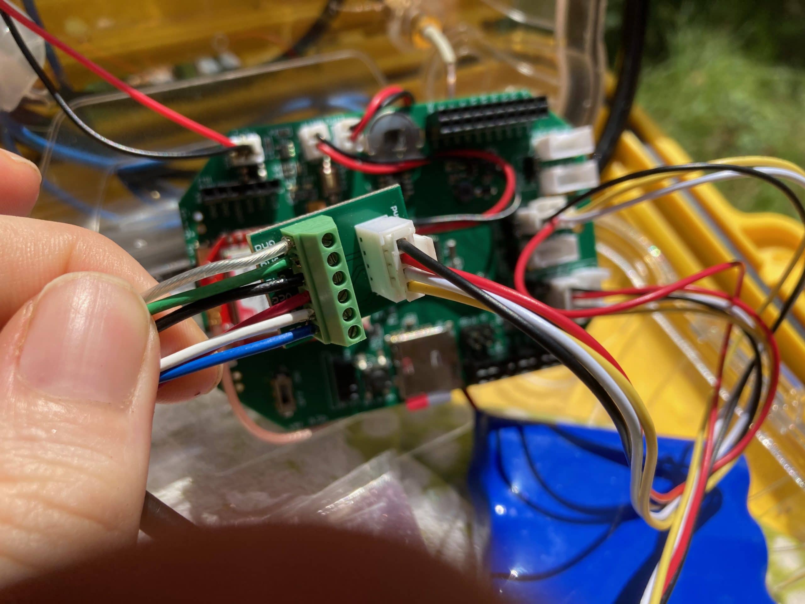
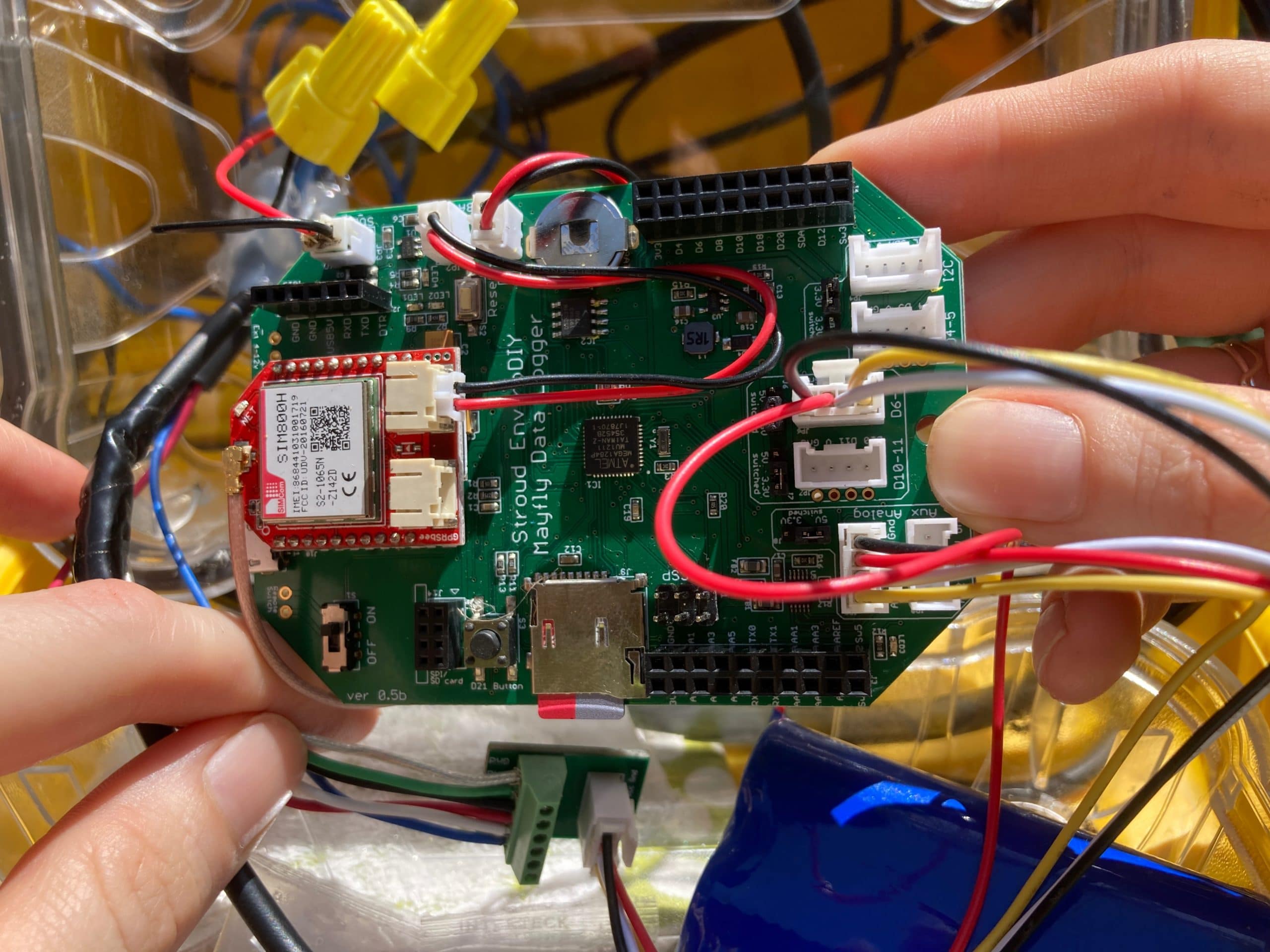
Arduino123456789101112131415161718192021222324252627282930313233343536373839404142434445464748495051525354555657585960616263646566676869707172737475767778798081828384858687888990919293949596979899100101102103104105106107108109110111112113114115116117118119120121122123124125126127128129130131132133134135136137138139140141142143144145146147148149150151152153154155156157158159/*######################### OVERVIEW #########################Example B: Changing the address of a sensor.This is a simple demonstration of the SDI-12 library for arduino.It discovers the address of the attached sensor and allows you to change it.########################## THE CIRCUIT ##########################The circuit: You should not have more than one SDI-12 device attached for this example.See:https://raw.github.com/Kevin-M-Smith/SDI-12-Circuit-Diagrams/master/basic_setup_no_usb.pngorhttps://raw.github.com/Kevin-M-Smith/SDI-12-Circuit-Diagrams/master/compat_setup_usb.png############################ COMPATIBILITY ############################This library requires the use of pin change interrupts (PCINT).Not all Arduino boards have the same pin capabilities.The known compatibile pins for common variants are shown below.Arduino Uno: All pins.Arduino Mega or Mega 2560:10, 11, 12, 13, 14, 15, 50, 51, 52, 53, A8 (62),A9 (63), A10 (64), A11 (65), A12 (66), A13 (67), A14 (68), A15 (69).Arduino Leonardo:8, 9, 10, 11, 14 (MISO), 15 (SCK), 16 (MOSI)########################## RESOURCES ##########################Written by Kevin M. Smith in 2013.Contact: SDI12@ethosengineering.orgThe SDI-12 specification is available at: http://www.sdi-12.org/The library is available at: https://github.com/EnviroDIY/Arduino-SDI-12*/#include <SDI12.h>#define SERIAL_BAUD 115200 // The baud rate for the output serial port#define DATA_PIN 7 // The pin of the SDI-12 data bus#define POWER_PIN 22 // The sensor power pin (or -1 if not switching power)// Define the SDI-12 busSDI12 mySDI12(DATA_PIN);String myCommand = ""; // empty to startchar oldAddress = '!'; // invalid address as placeholder// this checks for activity at a particular address// expects a char, '0'-'9', 'a'-'z', or 'A'-'Z'boolean checkActive(byte i){ // this checks for activity at a particular addressSerial.print("Checking address ");Serial.print((char)i);Serial.print("...");myCommand = "";myCommand += (char) i; // sends basic 'acknowledge' command [address][!]myCommand += "!";for(int j = 0; j < 3; j++){ // goes through three rapid contact attemptsmySDI12.sendCommand(myCommand);delay(30);if(mySDI12.available()) { // If we here anything, assume we have an active sensorSerial.println("Occupied");mySDI12.clearBuffer();return true;}else {Serial.println("Vacant"); // otherwise it is vacant.mySDI12.clearBuffer();}}return false;}void setup(){Serial.begin(SERIAL_BAUD);while(!Serial);Serial.println("Opening SDI-12 bus...");mySDI12.begin();delay(500); // allow things to settle// Power the sensors;if(POWER_PIN > 0){Serial.println("Powering up sensors...");pinMode(POWER_PIN, OUTPUT);digitalWrite(POWER_PIN, HIGH);delay(200);}}void loop(){boolean found = false; // have we identified the sensor yet?for(byte i = '0'; i <= '9'; i++){ // scan address space 0-9if(found) break;if(checkActive(i)){found = true;oldAddress = i;}}for(byte i = 'a'; i <= 'z'; i++){ // scan address space a-zif(found) break;if(checkActive(i)){found = true;oldAddress = i;}}for(byte i = 'A'; i <= 'Z'; i++){ // scan address space A-Zif(found) break;if(checkActive(i)){found = true;oldAddress = i;}}if(!found){Serial.println("No sensor detected. Check physical connections."); // couldn't find a sensor. check connections..}else{Serial.print("Sensor active at address "); // found a sensor!Serial.print(oldAddress);Serial.println(".");Serial.println("Enter new address."); // prompt for a new addresswhile(!Serial.available());char newAdd= Serial.read();// wait for valid responsewhile( ((newAdd<'0') || (newAdd>'9')) && ((newAdd<'a') || (newAdd>'z')) && ((newAdd<'A') || (newAdd>'Z'))){if(!(newAdd =='\n') || (newAdd =='\r') || (newAdd ==' ')) {Serial.println("Not a valid address. Please enter '0'-'9', 'a'-'A', or 'z'-'Z'.");}while(!Serial.available());newAdd = Serial.read();}/* the syntax of the change address command is:[currentAddress]A[newAddress]! */Serial.println("Readdressing sensor.");myCommand = "";myCommand += (char) oldAddress;myCommand += "A";myCommand += (char) newAdd;myCommand += "!";mySDI12.sendCommand(myCommand);/* wait for the response then throw it away byclearing the buffer with clearBuffer() */delay(300);mySDI12.clearBuffer();Serial.println("Success. Rescanning for verification.");Thank you for the response Shannon. I stripped and tinned the wires on the sensor, connected it to the 6-pin screw terminal as directed, connected the screw terminal with a grove cable to a SD-12 port on a Mayfly 1.1 board with the jumper moved to the 12v position. I also changed the sensor address to “2”. For some reason, I am getting an error reading of -9999, which I think means that my sensor isn’t getting power. I used the code in the menu a la carte example on github. I think the D22 pin is set to high in that example. Does anyone know what I could be doing wrong?
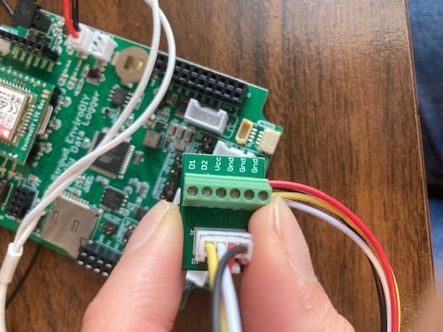
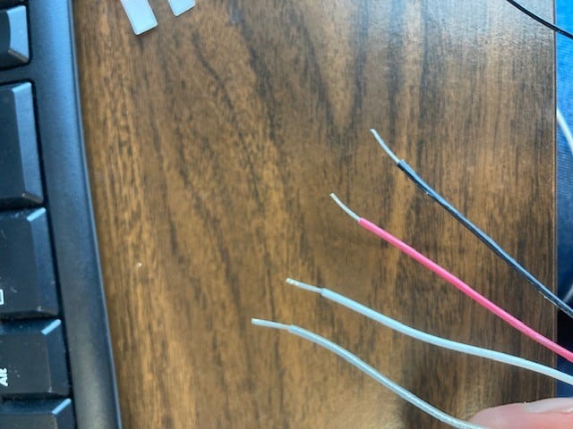
Hello, I have a few Mayfly dataloggers deployed with Campbell Scientific OBS3+ sensors. I recently purchased a Campbell Scientific ClariVUE10 sensor and a Mayfly 1.1 datalogger and am looking for some advice. I noticed that the new ClariVUE10 has only 4 wires (OBS 3+ has 6). Can I use the EnviroDIY Multipurpose 6-pin screw terminal to attach the new sensor to the board or do I need to purchase something else?
If I can use the 6-pin, which wires plug into which screw terminals? White is SDI-12 data, red is 12V power, clear is shield and black is ground.
Thanks!
It turns out that I had had wires of the OBS3+ in the wrong screw terminals. Rewiring the high and low turbidity readings within a reasonable range. The problem now is that the sensor is not reading accurately. High turbidity always reads about 3 NTU and low turbidity always reads about 1 NTU. I have measured with two handheald turbidity meters and they were both reading 11-12 NTU. I checked and the grove cable is connected to the AA0-AA1 terminal and the aux analog port is switched from 3V – 5V. I’ve attached a photo of my wiring. Thanks!
Attachments:
2019-03-19 at 2:19 PM in reply to: Attaching a Campbell Scientific OBS3+ turbidity sensor to Mayfly #12863Great, thanks for your quick reply. Is there a way to connect the sensor to the board without the screw terminal adapter?
-
AuthorPosts