
Home › Forums › Environmental Sensors › Turbidity Sensor Information/Questions
- This topic has 11 replies, 4 voices, and was last updated 2022-10-05 at 4:20 PM by
 Shannon Hicks.
-
AuthorPosts
-
-
2022-02-28 at 11:34 AM #16627
Hello EnviroDIY Mayfly community,
I’ve watched many of the videos that are provided by the Stroud Center. Though some information (which I’m sure will be added in the updated manual) do not necessarily go in-depth about the turbidity sensor (ClariVUE 10) since it is an add-on sensor. So here is some information if you are in need of info on the turbidity sensor:– yes, you’ll have to drill a 3rd hole in the pelican box
More info if needed:
“Figure 5.2.1 D. Cable glands (x3).The two large cable glands (1/2” NPT; http://www.mcmaster.com: Item number 69915K53) are for the CTD and OBS-3+ cables. The small cable gland (3/8” NPT; http://www.mcmaster.com: Item number 69915K52) is for solar panel cable. Cable glands allow wires to enter the logger box while at the same time remaining waterproof and submersible. Holes must be drilled and tapped into the Pelican case to accommodate the 3/8” NPT and 1/2” NPT cable glands. The recommended drills for those taps are 37/64” and 23/32″
Some other remaining questions I have:
I noticed that a 4-pin Molex connector is needed for this sensor, which I found on the McMaster website. According to the manual, I did not see the size for this – I may have missed it, as there is quite a bit of information to go through
The ClariVUE 10 uses C, SDI – 12, or U configured for SDI – 12 for the logging connection, power, ground, and shield. Do you know what the wire connector size is, as well as the wire configuration for the Molex connector and board connection?
Idea/Question:
I had an idea I wanted to run by, would it be okay to add anti-fouling tape to the outside of the sensors (obviously not right on the optical sensor part) to help reduce algal growth etc.? Has anyone done this with their sensors?
In no way would this prevent regular maintenance but may help deter significant growth on the parts overall. Or would this in some way disrupt the electronics etc.? – Something that others may want to consider when implementing these units.
Many thanks in advance,
Emily Mayer
-
2022-02-28 at 3:56 PM #16630
There’s a few things in your post to clarify to make sure we’re talking about the same equipment. The various instructional videos and manuals we’ve released in the past few years cover several different configurations of sensors and cables and equipment. The majority of the stations we deployed before 2020 had a Meter Group CTD sensor and a Campbell Scientific OBS3+ turbidity sensor on them. We also used to sell Monitoring Station Kits that contained Pelican 1120 cases that were pre-drilled and tapped for 3 cable glands: one for solar panel cable, one for CTD sensor, and one for OBS3+ turbidity sensor. The CTD and old turbidity sensors had cables that required the same diameter cable glands, so we used the 69915K53 size (0.24″-0.47″ cables and 1/2″ NPT threads).
Campbell Scientific discontinued the OBS3+ turbidity sensor a few years ago and since there was not a ready replacement, we stopped including the cable gland and pre-drilling the holes in the Pelican cases that we sold, since most people were just building CTD-only stations.
A few months ago, Campbell Scientific released the ClariVUE10 turbidity sensor, and it has a cable with a smaller diameter. Therefore we recommend using a 69915K54 cable gland (0.2″-0.35″ range, 1/2″ NPT) for the ClariVUE10 turbidity sensor cable.
The Meter Group Hydros21 sensor can be purchased with either bare wire leads on the end of the cable, or a 3.5mm stereo headphone plug. We usually tell users to choose the stereo plug because it’s the easiest to use, and we developed a Grove-to-3.5mm-jack adapter board many years ago for connecting the stereo plug to the Grove jack of the EnviroDIY Mayfly. The ClariVUE turbidity sensor cable has bare wires on the end, there is no connecter on the cable. We developed the multipurpose 6-pin screw terminal board for using bare wire sensors like the ClariVUE with the Mayfly. You could also use that same screw terminal board for connecting a Hydros21 CTD sensor to the Mayfly if you bought the sensor with bare wires instead of the headphone jack. It’s worth noting however that we may need to develop a new screw terminal board with some additional circuitry on it to properly communicate with some SDI-12 sensors like the ClariVUE10, so we’re still working on this, which is why we haven’t published official instructions on how to connect a ClariVUE10 to the Mayfly yet.
The term “Molex connectors” refers to a wide variety of sizes and types of connectors so I’m not sure to which ones you’re referring, but there aren’t any Molex connectors anywhere on the EnviroDIY Mayfly, and we don’t use them in any of our recommended instructions. Are you referring to the Grove cables and Grove jacks (the six or seven white, 4-pin polarized sockets on the Mayfly)? All you should need to connect a ClariVUE10 to the Mayfly is the screw terminal board mentioned above, and a short double-ended Grove cable, like the ones we include in the Starter Kit or the Monitoring Station Kit, or that can be found from various sellers on Amazon.
Another thing to note, the ClariVUE10 sensors require 9.6v to 18v DC to operate. The previous EnviroDIY Mayfly boards we sold prior to the fall of 2021 were not capable of powering these sensors. The Mayfly v1.0 we released in October and the new v1.1 board releasing next week are able to generate a 12v power source capable of powering the sensor, but you have to move the small jumper next to the Grove jack to change the voltage level sent to that jack to match whatever sensor you’re connecting (your options are 3.3v, 5v, and 12v). So instruction for all these steps are being finalized now, along with writing and testing new code examples for all the major configurations we recommend, which will include the ClariVUE10.
As for the anti-fouling tape, it’s probably not necessary. The ClariVUE10 is manufactured with a copper end-plate, so algal growth right around the sensor window should probably be reduced, however the sapphire windows themselves will need to be cleaned regularly, plus we find that the majority of fouling issued to our turbidity sensors is cause by large debris like leaves, sticks, mud, rocks, etc, which is why still suggest frequent service visits to the station, especially for stations that don’t transmit their data to an online portal like Monitor My Watershed.
-
2022-02-28 at 6:05 PM #16636
Hi Shannon,
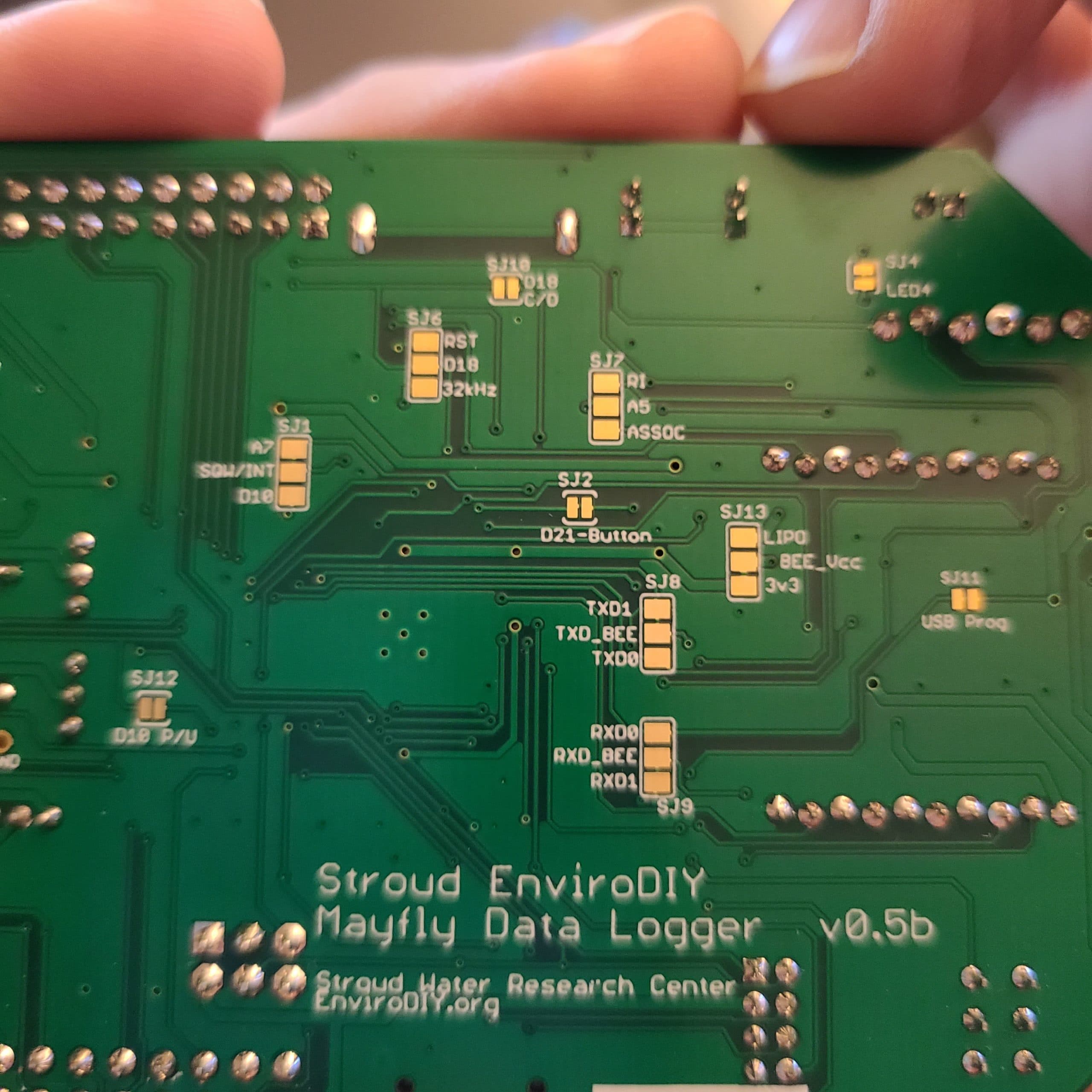
Thank you for the information. I just wanted to clarify something mentioned that may be a roadblock with installing these turbidity sensors. The boards we are using are the Mayfly Data Logger v0.5b (As indicated on the back of the board- pic attached). These will not be able to power the ClariVUE 10, as they only have a maximum voltage output of 5V? Correct?
Thank you,
Emily
Attachments:
-
2022-07-08 at 11:43 AM #17143
Given the popularity, complexity, and expense of turbidity sensors, the team here at the Stroud Center has compiled a snapshot of some commercially-available options that may help people decide on the best option. This table likely excludes many vendors and models, and it only summarizes sensors that we have recently used or investigated. In addition to these commercially-available options, you might consider do-it-yourself options like OpenOBS, a well-document project on Github with a peer-reviewed background. Another open-source DIY turbidity sensor is described by Droujko and Molnar 2022 in Nature, Scientific Reports.
- Campbell Scientific Clari-Vue (recently replaced the OBS3)
- no wiper
- pre-calibrated
- SDI-12 at 5V
- 9.6-18V (nominally 12V)
- compatible with Mayfly version 1.1 (or any Mayfly version with an interface board with separate 12V supply)
- compatible with Modular Sensors
- $$ on a scale of $ (<$1000), $$ ($1000 – $2000), and $$$ (>$2000)
- Yosemitech Y511-A
- includes wiper (the Yosemitech Y510-B does not include a wiper)
- pre-calibrated
- Modbus over RS485
- 5-12V (nominally 12V)
- compatible with Mayfly version 1.1 with EnviroDIY RS485 adapter (or any Mayfly with both separate 12V power supply and RS485 adapter)
- compatible with Modular Sensors library
- $
- Turner Designs Turbidity Plus
- available with and without wiper
- not pre-calibrated
- analog voltage communication
- 3-15V
- compatible with Mayfly version 1.1 with multi-purpose 6 pin screw terminal grove adapter (or any Mayfly with a voltage divider with separate 12V power supply)
- not compatible with Modular Sensors library
- $$
- Turner Designs Cyclops 7
- no wiper, but has an optional cap to protect the sensor window
- not pre-calibrated
- analog voltage communication
- 3-15V
- compatible with any Mayfly version with multi-purpose 6 pin screw terminal grove adapter
- compatible with Modular Sensors library
- $$
- Analite NEP-5000
- includes wiper
- pre-calibrated
- SDI-12 or Modbus over RS485 or analog communication
- 8-30V
- compatible with Mayfly version 1.1 (additional adapters required depending on communication protocol used)
- not compatible with Modular Sensors library
- $$$
- Campbell Scientific Clari-Vue (recently replaced the OBS3)
-
2022-09-13 at 2:11 PM #17318
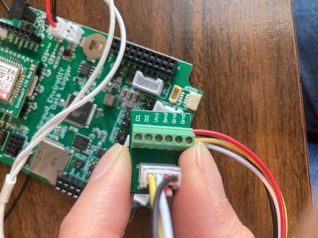
Hello, I have a few Mayfly dataloggers deployed with Campbell Scientific OBS3+ sensors. I recently purchased a Campbell Scientific ClariVUE10 sensor and a Mayfly 1.1 datalogger and am looking for some advice. I noticed that the new ClariVUE10 has only 4 wires (OBS 3+ has 6). Can I use the EnviroDIY Multipurpose 6-pin screw terminal to attach the new sensor to the board or do I need to purchase something else?
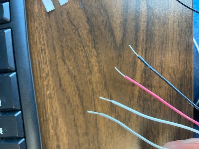
If I can use the 6-pin, which wires plug into which screw terminals? White is SDI-12 data, red is 12V power, clear is shield and black is ground.
Thanks!
-
2022-09-15 at 10:00 PM #17339
The old Campbell OBS3 turbidity sensor was an analog-output sensor that had 2 separate voltage outputs, one 5v power supply wire, and 3 ground wires, which is why I designed the old version of the 6-pin screw terminal board that way, because we primarily used it with the OBS3 sensors and connected it to one of the Aux Analog Grove jacks on the Mayfly board.
The Campbell ClariVUE10 sensor is a digital-output sensor that uses SDI-12 protocol and only has one signal output and 2 ground wires (plus the one 12v power wire). And because we wanted a new screw terminal board that gave people the option of also combining signal pins (for hooking two SDI-12 sensors to one board) or adding resistor dividers for analog sensors, I designed the new multi-purpose screw terminal board to replace the old version and give users the option of configuring the board for different types of sensors.
In your case, you are able to use the old style screw terminal board with your Mayfly v1.1 board and a ClariVUE 10 sensor if you connect the wires as follows:
- Black wire (ground) and clear wire (shield) to any of the screw terminal board’s GND pins
- Red wire (12v power) to the screw terminal board’s VCC pin
- White wire (SDI-12 data) to the screw terminal board’s D2 pin
Then you’ll need to connect the Grove cable from the screw terminal board to either of the two Grove sockets in the center of the Mayfly (the one’s labeled D4-7 SDI-12). You’ll also want to make sure you move the little jumper block next to that one socket from the default 3v position to the 12v position. Once that is connected and the switched power (D22) is set high so that the sensor is powered, you can communicate with it through the D7 pin. The sensor ships from the factory with the default SDI-12 address of “0”, so you might want to change it to something else if you don’t want it to conflict with any other SDI-12 sensors you connect to the Mayfly at the same time. If you want to use a Hydros21 CTD sensor along with the ClariVUE10, connect the Hydros21 to the Mayfly’s other SDI-12 Grove jack and keep that one at the default 3v jumper position (we’ve found that the Hydros21 sensors work best at 3v), but you’ll have to change the Hydros21 channel number to something other than its default “0” channel, otherwise it doesn’t respond properly to measurement commands. We typically use “1” for the CTD channel and “2” for the turbidity channel. We haven’t published an example sketch of using a ClariVUE10 sensor yet because we’re finalizing our testing of various configurations with the new sensors, but I’m hoping to publish that example next week on Github.
Readers should note that the Mayfly v1.1 boards are the only ones capable of powering a ClariVUE10 turbidity sensor directly from the Mayfly board. Older Mayfly boards (v1.0 and earlier) will need a separate 12v boost adapter (coming soon) or a separate 12v power source to power the sensor directly since the older Mayfly board don’t have the ability to generate the proper power for the ClariVUE sensors.
-
2022-10-04 at 5:18 PM #17368
Thank you for the response Shannon. I stripped and tinned the wires on the sensor, connected it to the 6-pin screw terminal as directed, connected the screw terminal with a grove cable to a SD-12 port on a Mayfly 1.1 board with the jumper moved to the 12v position. I also changed the sensor address to “2”. For some reason, I am getting an error reading of -9999, which I think means that my sensor isn’t getting power. I used the code in the menu a la carte example on github. I think the D22 pin is set to high in that example. Does anyone know what I could be doing wrong?
-
2022-10-05 at 11:58 AM #17370
When you changed the SDI12 address of the turbidity sensor to “2”, did you use the same Mayfly board and the “SDI12/b_address_change” example sketch that comes with our libraries, or did you change the address with a different board or instrument?
-
-
2022-10-05 at 12:15 PM #17371
I used the Mayfly 1.1 board and the sketch below. Thank you for helping me!
Arduino123456789101112131415161718192021222324252627282930313233343536373839404142434445464748495051525354555657585960616263646566676869707172737475767778798081828384858687888990919293949596979899100101102103104105106107108109110111112113114115116117118119120121122123124125126127128129130131132133134135136137138139140141142143144145146147148149150151152153154155156157158159/*######################### OVERVIEW #########################Example B: Changing the address of a sensor.This is a simple demonstration of the SDI-12 library for arduino.It discovers the address of the attached sensor and allows you to change it.########################## THE CIRCUIT ##########################The circuit: You should not have more than one SDI-12 device attached for this example.See:https://raw.github.com/Kevin-M-Smith/SDI-12-Circuit-Diagrams/master/basic_setup_no_usb.pngorhttps://raw.github.com/Kevin-M-Smith/SDI-12-Circuit-Diagrams/master/compat_setup_usb.png############################ COMPATIBILITY ############################This library requires the use of pin change interrupts (PCINT).Not all Arduino boards have the same pin capabilities.The known compatibile pins for common variants are shown below.Arduino Uno: All pins.Arduino Mega or Mega 2560:10, 11, 12, 13, 14, 15, 50, 51, 52, 53, A8 (62),A9 (63), A10 (64), A11 (65), A12 (66), A13 (67), A14 (68), A15 (69).Arduino Leonardo:8, 9, 10, 11, 14 (MISO), 15 (SCK), 16 (MOSI)########################## RESOURCES ##########################Written by Kevin M. Smith in 2013.Contact: SDI12@ethosengineering.orgThe SDI-12 specification is available at: http://www.sdi-12.org/The library is available at: https://github.com/EnviroDIY/Arduino-SDI-12*/#include <SDI12.h>#define SERIAL_BAUD 115200 // The baud rate for the output serial port#define DATA_PIN 7 // The pin of the SDI-12 data bus#define POWER_PIN 22 // The sensor power pin (or -1 if not switching power)// Define the SDI-12 busSDI12 mySDI12(DATA_PIN);String myCommand = ""; // empty to startchar oldAddress = '!'; // invalid address as placeholder// this checks for activity at a particular address// expects a char, '0'-'9', 'a'-'z', or 'A'-'Z'boolean checkActive(byte i){ // this checks for activity at a particular addressSerial.print("Checking address ");Serial.print((char)i);Serial.print("...");myCommand = "";myCommand += (char) i; // sends basic 'acknowledge' command [address][!]myCommand += "!";for(int j = 0; j < 3; j++){ // goes through three rapid contact attemptsmySDI12.sendCommand(myCommand);delay(30);if(mySDI12.available()) { // If we here anything, assume we have an active sensorSerial.println("Occupied");mySDI12.clearBuffer();return true;}else {Serial.println("Vacant"); // otherwise it is vacant.mySDI12.clearBuffer();}}return false;}void setup(){Serial.begin(SERIAL_BAUD);while(!Serial);Serial.println("Opening SDI-12 bus...");mySDI12.begin();delay(500); // allow things to settle// Power the sensors;if(POWER_PIN > 0){Serial.println("Powering up sensors...");pinMode(POWER_PIN, OUTPUT);digitalWrite(POWER_PIN, HIGH);delay(200);}}void loop(){boolean found = false; // have we identified the sensor yet?for(byte i = '0'; i <= '9'; i++){ // scan address space 0-9if(found) break;if(checkActive(i)){found = true;oldAddress = i;}}for(byte i = 'a'; i <= 'z'; i++){ // scan address space a-zif(found) break;if(checkActive(i)){found = true;oldAddress = i;}}for(byte i = 'A'; i <= 'Z'; i++){ // scan address space A-Zif(found) break;if(checkActive(i)){found = true;oldAddress = i;}}if(!found){Serial.println("No sensor detected. Check physical connections."); // couldn't find a sensor. check connections..}else{Serial.print("Sensor active at address "); // found a sensor!Serial.print(oldAddress);Serial.println(".");Serial.println("Enter new address."); // prompt for a new addresswhile(!Serial.available());char newAdd= Serial.read();// wait for valid responsewhile( ((newAdd<'0') || (newAdd>'9')) && ((newAdd<'a') || (newAdd>'z')) && ((newAdd<'A') || (newAdd>'Z'))){if(!(newAdd =='\n') || (newAdd =='\r') || (newAdd ==' ')) {Serial.println("Not a valid address. Please enter '0'-'9', 'a'-'A', or 'z'-'Z'.");}while(!Serial.available());newAdd = Serial.read();}/* the syntax of the change address command is:[currentAddress]A[newAddress]! */Serial.println("Readdressing sensor.");myCommand = "";myCommand += (char) oldAddress;myCommand += "A";myCommand += (char) newAdd;myCommand += "!";mySDI12.sendCommand(myCommand);/* wait for the response then throw it away byclearing the buffer with clearBuffer() */delay(300);mySDI12.clearBuffer();Serial.println("Success. Rescanning for verification.");-
2022-10-05 at 12:30 PM #17373
When you power up the ClariVUE10 sensor, we’ve found that it take a few seconds to warm up before the Mayfly can “see” it. So when that sketch cycles through all of the available numbers and letters, it usually doesn’t see the ClariVUE until the second loop through.
So when you first connect the sensor from the factory and run the sketch, it’ll run through one full loop before finding it on address “0”. Then you can either leave it there or enter another address, in your case “2”. Then it should go through the loop check again and say that it found the sensor on address “2”. If you run that sketch at any time or the “c_check_all_addresses” sketch, it should always find the sensor at address 2. If that’s all correct, then the issue is just with your logging sketch. You can post it here if you want, just be sure to edit out any personal information like UUIDs or wifi APN info.
-
-
2022-10-05 at 4:04 PM #17374
I uploaded the “SDI12/b_address_change” sketch and the address of the sensor is correctly assigned at “2”. My sketch is below. I modified the DWRI CitSci code for the ClariVUE. Thanks for taking a look!
Arduino123456789101112131415161718192021222324252627282930313233343536373839404142434445464748495051525354555657585960616263646566676869707172737475767778798081828384858687888990919293949596979899100101102103104105106107108109110111112113114115116117118119120121122123124125126127128129130131132133134135136137138139140141142143144145146147148149150151152153154155156157158159160161162163164165166167168169170171172173174175176177178179180181182183184185186187188189190191192193194195196197198199200201202203204205206207208209210211212213214215216217218219220221222223224225226227228229230231232233234235236237238239240241242243244245246247248249250251252253254255256257258259260261262263264265266267268269270271272273274275276277278279280281282283284285286287288289290291292293294295296297298299300301302303304305306307308309310311312313314315316317318319320321322323324325326327328329330331332333334335336337338339340341342343344345346347348349350351352353354355356357358359360361362363364365366367368369370371372373374375376377378379380381382383384385386387388389390391392393394395/** =========================================================================* @file DRWI_SIM7080LTE.ino* @brief Example for DRWI CitSci LTE sites.** This example shows proper settings for the following configuration:** Mayfly v1.1 board* EnviroDIY SIM7080 LTE module (with Hologram SIM card)* ES2 sensor* Campbell Scientific ClareVUE10 Turbidity sensor** @author Sara Geleskie Damiano <sdamiano@stroudcenter.org>* @copyright (c) 2017-2022 Stroud Water Research Center (SWRC)* and the EnviroDIY Development Team* This example is published under the BSD-3 license.** Hardware Platform: EnviroDIY Mayfly Arduino Datalogger** DISCLAIMER:* THIS CODE IS PROVIDED "AS IS" - NO WARRANTY IS GIVEN.** CASSI 6 version 2* ======================================================================= */// ==========================================================================// Defines for the Arduino IDE// NOTE: These are ONLY needed to compile with the Arduino IDE.// If you use PlatformIO, you should set these build flags in your// platformio.ini// ==========================================================================/** Start [defines] */#ifndef TINY_GSM_RX_BUFFER#define TINY_GSM_RX_BUFFER 64#endif#ifndef TINY_GSM_YIELD_MS#define TINY_GSM_YIELD_MS 2#endif/** End [defines] */// ==========================================================================// Include the libraries required for any data logger// ==========================================================================/** Start [includes] */// The Arduino library is needed for every Arduino program.#include <Arduino.h>// EnableInterrupt is used by ModularSensors for external and pin change// interrupts and must be explicitly included in the main program.#include <EnableInterrupt.h>// Include the main header for ModularSensors#include <ModularSensors.h>/** End [includes] */// ==========================================================================// Data Logging Options// ==========================================================================/** Start [logging_options] */// The name of this program fileconst char* sketchName = "CASSI6.ino";// Logger ID, also becomes the prefix for the name of the data file on SD cardconst char* LoggerID = "CASSI6";// How frequently (in minutes) to log dataconst uint8_t loggingInterval = 3;// Your logger's timezone.const int8_t timeZone = -5; // Eastern Standard Time// NOTE: Daylight savings time will not be applied! Please use standard time!// Set the input and output pins for the logger// NOTE: Use -1 for pins that do not applyconst int32_t serialBaud = 57600; // Baud rate for debuggingconst int8_t greenLED = 8; // Pin for the green LEDconst int8_t redLED = 9; // Pin for the red LEDconst int8_t buttonPin = 21; // Pin for debugging mode (ie, button pin)const int8_t wakePin = 31; // MCU interrupt/alarm pin to wake from sleep// Mayfly 0.x D31 = A7const int8_t sdCardPwrPin = -1; // MCU SD card power pinconst int8_t sdCardSSPin = 12; // SD card chip select/slave select pinconst int8_t sensorPowerPin = 22; // MCU pin controlling main sensor power/** End [logging_options] */// ==========================================================================// Wifi/Cellular Modem Options// ==========================================================================/** Start [sim_com_sim7080] */// For almost anything based on the SIMCom SIM7080G#include <modems/SIMComSIM7080.h>// Create a reference to the serial port for the modemHardwareSerial& modemSerial = Serial1; // Use hardware serial if possibleconst int32_t modemBaud = 9600; // SIM7080 does auto-bauding by default, but// for simplicity we set to 9600// Modem Pins - Describe the physical pin connection of your modem to your board// NOTE: Use -1 for pins that do not applyconst int8_t modemVccPin = 18;// MCU pin controlling modem power --- Pin 18 is the power enable pin for the// bee socket on Mayfly v1.0, use -1 if using Mayfly 0.5b or if the bee socket// is constantly powered (ie you changed SJ18 on Mayfly 1.x to 3.3v)const int8_t modemStatusPin = 19; // MCU pin used to read modem statusconst int8_t modemSleepRqPin = 23; // MCU pin for modem sleep/wake requestconst int8_t modemLEDPin = redLED; // MCU pin connected an LED to show modem// status// Network connection informationconst char* apn ="hologram"; // APN connection name, typically Hologram unless you have a// different provider's SIM card. Change as needed// Create the modem objectSIMComSIM7080 modem7080(&modemSerial, modemVccPin, modemStatusPin,modemSleepRqPin, apn);// Create an extra reference to the modem by a generic nameSIMComSIM7080 modem = modem7080;/** End [sim_com_sim7080] */// ==========================================================================// Using the Processor as a Sensor// ==========================================================================/** Start [processor_sensor] */#include <sensors/ProcessorStats.h>// Create the main processor chip "sensor" - for general metadataconst char* mcuBoardVersion = "v1.1";ProcessorStats mcuBoard(mcuBoardVersion);/** End [processor_sensor] */// ==========================================================================// Maxim DS3231 RTC (Real Time Clock)// ==========================================================================/** Start [ds3231] */#include <sensors/MaximDS3231.h>// Create a DS3231 sensor objectMaximDS3231 ds3231(1);/** End [ds3231] *///\// ==========================================================================// Decagon ES2 Conductivity and Temperature Sensor// ==========================================================================/** Start [es2] */#include <sensors/DecagonES2.h>// NOTE: Use -1 for any pins that don't apply or aren't being used.const char* ES2SDI12address = "1"; // The SDI-12 Address of the ES2const int8_t ES2Power = sensorPowerPin; // Power pinconst int8_t ES2Data = 7; // The SDI12 data pinconst uint8_t ES2NumberReadings = 5;// Create a Decagon ES2 sensor objectDecagonES2 es2(*ES2SDI12address, ES2Power, ES2Data, ES2NumberReadings);\/** End [es2] */\// ==========================================================================// Campbell ClariVUE Turbidity Sensor// ==========================================================================/** Start [clarivue] */#include <sensors/CampbellClariVUE10.h>const char* ClariVUESDI12address = "2"; // The SDI-12 Address of the ClariVUE10const int8_t ClariVUEPower = sensorPowerPin; // Power pin (-1 if unconnected)const int8_t ClariVUEData = 7; // The SDI12 data pin// NOTE: you should NOT take more than one readings. THe sensor already takes// and averages 8 by default.// Create a Campbell ClariVUE10 sensor objectCampbellClariVUE10 clarivue(*ClariVUESDI12address, ClariVUEPower, ClariVUEData);\// ==========================================================================// Creating the Variable Array[s] and Filling with Variable Objects// ==========================================================================/** Start [variable_arrays] */Variable* variableList[] = {new DecagonES2_Cond (&es2),new DecagonES2_Temp (&es2),new CampbellClariVUE10_Turbidity(&clarivue, "", "Turbidity"),new MaximDS3231_Temp(&ds3231),new ProcessorStats_Battery(&mcuBoard),new Modem_SignalPercent(&modem),};// All UUID's, device registration, and sampling feature information can be// pasted directly from Monitor My Watershed.// To get the list, click the "View token UUID list" button on the upper right// of the site page.// *** CAUTION --- CAUTION --- CAUTION --- CAUTION --- CAUTION ***// Check the order of your variables in the variable list!!!// Be VERY certain that they match the order of your UUID's!// Rearrange the variables in the variable list ABOVE if necessary to match!// Do not change the order of the variables in the section below.// *** CAUTION --- CAUTION --- CAUTION --- CAUTION --- CAUTION ***// Replace all of the text in the following section with the UUID array from// MonitorMyWatershed/* clang-format off */// --------------------- Beginning of Token UUID List ---------------------const char *UUIDs[] = // UUID array for device sensors{"abcdefghijklmnopqrstuvwxyz", // Electrical conductivity (Decagon_ES-2_Cond)"abcdefghijklmnopqrstuvwxyz", // Temperature (Decagon_ES-2_Temp)"abcdefghijklmnopqrstuvwxyz", // Turbidity (Campbell_OBS3_Turb)"abcdefghijklmnopqrstuvwxyz", // Temperature (Maxim_DS3231_Temp)"abcdefghijklmnopqrstuvwxyz", // Battery voltage (EnviroDIY_Mayfly_Batt)"abcdefghijklmnopqrstuvwxyz" // Percent full scale (EnviroDIY_LTEB_SignalPercent)};const char *registrationToken = "abcdefghijklmnopqrstuvwxyz"; // Device registration tokenconst char *samplingFeature = "abcdefghijklmnopqrstuvwxyz"; // Sampling feature UUID// ----------------------- End of Token UUID List -----------------------/* clang-format on */// Count up the number of pointers in the arrayint variableCount = sizeof(variableList) / sizeof(variableList[6]);// Create the VariableArray objectVariableArray varArray(variableCount, variableList, UUIDs);/** End [variable_arrays] */// ==========================================================================// The Logger Object[s]// ==========================================================================/** Start [loggers] */// Create a new logger instanceLogger dataLogger(LoggerID, loggingInterval, &varArray);/** End [loggers] */// ==========================================================================// Creating Data Publisher[s]// ==========================================================================/** Start [publishers] */// Create a data publisher for the Monitor My Watershed/EnviroDIY POST endpoint#include <publishers/EnviroDIYPublisher.h>EnviroDIYPublisher EnviroDIYPOST(dataLogger, &modem.gsmClient,registrationToken, samplingFeature);/** End [publishers] */// ==========================================================================// Working Functions// ==========================================================================/** Start [working_functions] */// Flashes the LED's on the primary boardvoid greenredflash(uint8_t numFlash = 4, uint8_t rate = 75) {for (uint8_t i = 0; i < numFlash; i++) {digitalWrite(greenLED, HIGH);digitalWrite(redLED, LOW);delay(rate);digitalWrite(greenLED, LOW);digitalWrite(redLED, HIGH);delay(rate);}digitalWrite(redLED, LOW);}// Reads the battery voltage// NOTE: This will actually return the battery level from the previous update!float getBatteryVoltage() {if (mcuBoard.sensorValues[0] == -9999) mcuBoard.update();return mcuBoard.sensorValues[0];}// ==========================================================================// Arduino Setup Function// ==========================================================================/** Start [setup] */void setup() {// Start the primary serial connectionSerial.begin(serialBaud);// Print a start-up note to the first serial portSerial.print(F("Now running "));Serial.print(sketchName);Serial.print(F(" on Logger "));Serial.println(LoggerID);Serial.println();Serial.print(F("Using ModularSensors Library version "));Serial.println(MODULAR_SENSORS_VERSION);Serial.print(F("TinyGSM Library version "));Serial.println(TINYGSM_VERSION);Serial.println();// Start the serial connection with the modemmodemSerial.begin(modemBaud);// Set up pins for the LED'spinMode(greenLED, OUTPUT);digitalWrite(greenLED, LOW);pinMode(redLED, OUTPUT);digitalWrite(redLED, LOW);// Blink the LEDs to show the board is on and starting upgreenredflash();pinMode(20, OUTPUT); // for proper operation of the onboard flash memory// chip's ChipSelect (Mayfly v1.0 and later)// Set the timezones for the logger/data and the RTC// Logging in the given time zoneLogger::setLoggerTimeZone(timeZone);// It is STRONGLY RECOMMENDED that you set the RTC to be in UTC (UTC+0)Logger::setRTCTimeZone(0);// Attach the modem and information pins to the loggerdataLogger.attachModem(modem);modem.setModemLED(modemLEDPin);dataLogger.setLoggerPins(wakePin, sdCardSSPin, sdCardPwrPin, buttonPin,greenLED);// Begin the loggerdataLogger.begin();// Note: Please change these battery voltages to match your battery// Set up the sensors, except at lowest battery levelif (getBatteryVoltage() > 3.4) {Serial.println(F("Setting up sensors..."));varArray.setupSensors();}/** Start [setup_sim7080] */modem.setModemWakeLevel(HIGH); // ModuleFun Bee inverts the signalmodem.setModemResetLevel(HIGH); // ModuleFun Bee inverts the signalSerial.println(F("Waking modem and setting Cellular Carrier Options..."));modem.modemWake(); // NOTE: This will also set up the modemmodem.gsmModem.setBaud(modemBaud); // Make sure we're *NOT* auto-bauding!modem.gsmModem.setNetworkMode(38); // set to LTE only// 2 Automatic// 13 GSM only// 38 LTE only// 51 GSM and LTE onlymodem.gsmModem.setPreferredMode(1); // set to CAT-M// 1 CAT-M// 2 NB-IoT// 3 CAT-M and NB-IoT/** End [setup_sim7080] */// Sync the clock if it isn't valid or we have battery to spareif (getBatteryVoltage() > 3.55 || !dataLogger.isRTCSane()) {// Synchronize the RTC with NIST// This will also set up the modemdataLogger.syncRTC();}// Create the log file, adding the default header to it// Do this last so we have the best chance of getting the time correct and// all sensor names correct// Writing to the SD card can be power intensive, so if we're skipping// the sensor setup we'll skip this too.if (getBatteryVoltage() > 3.4) {Serial.println(F("Setting up file on SD card"));dataLogger.turnOnSDcard(true); // true = wait for card to settle after power updataLogger.createLogFile(true); // true = write a new headerdataLogger.turnOffSDcard(true); // true = wait for internal housekeeping after write}// Call the processor sleepSerial.println(F("Putting processor to sleep\n"));dataLogger.systemSleep();}/** End [setup] */// ==========================================================================// Arduino Loop Function// ==========================================================================/** Start [loop] */// Use this short loop for simple data logging and sendingvoid loop() {// Note: Please change these battery voltages to match your battery// At very low battery, just go back to sleepif (getBatteryVoltage() < 3.4) {dataLogger.systemSleep();}// At moderate voltage, log data but don't send it over the modemelse if (getBatteryVoltage() < 3.55) {dataLogger.logData();}// If the battery is good, send the data to the worldelse {dataLogger.logDataAndPublish();}}/** End [loop] */ -
2022-10-05 at 4:20 PM #17375
Thanks for posting your code, I edited your post to put it into the “code formatting” window that you can use when pasting code into our forum. It’s the little unlabled icon that looks like this: “<>” in the toolbar above the text entry box.
Your issue is caused by an error on line 186. It should look like this:
Arduino1new CampbellClariVUE10_Turbidity(&clarivue),You can also include another variable to report the Clarivue temperature (because the sensor also reports water temperature) by adding this line to your variable list:
Arduino1new CampbellClariVUE10_Temp(&clarivue),I haven’t published the official example code for using a ClariVUE10 sensor yet because they haven’t added the sensor to the list of supported sensors on the MonitorMyWatershed website. Once it gets added to MMW, I will publish the example, but it’s essentially exactly what you have above, minus the ES2 sensor, and with the correct variable declaration that I just posted here.
-
-
AuthorPosts
- You must be logged in to reply to this topic.