
Home › Forums › Environmental Sensors › Problems with OBS3+
Tagged: #jsterling
- This topic has 13 replies, 6 voices, and was last updated 2021-05-23 at 9:41 PM by
 James_NZ.
-
AuthorPosts
-
-
2020-08-31 at 2:28 PM #14545
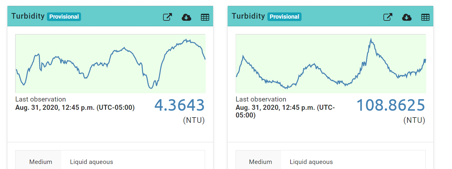
I have recently put two Mayflys with OBS3+ turbidity sensors out in the field and they are not reading correctly when confirmed with a handheld nephelometer. The low readout is reading too low and the high is reading too high. I’ve triple checked my code and the calibration curves are correct. Does anyone have any idea why this is happening? I have one other Mayfly with OBS3+ that I put out late last year that is reading perfectly.
Attachments:
-
2020-08-31 at 4:38 PM #14547
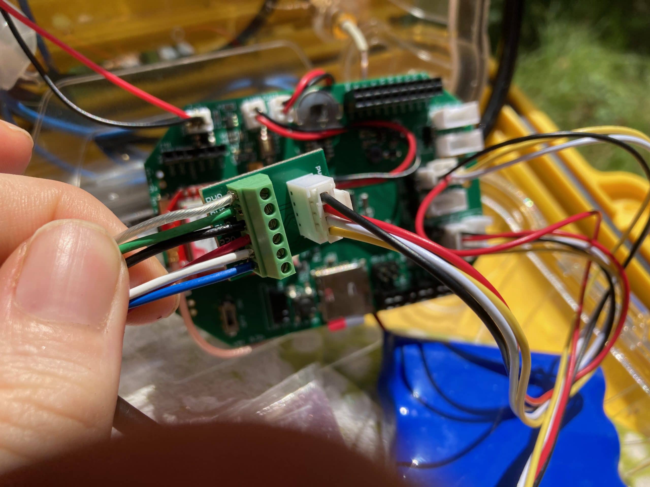
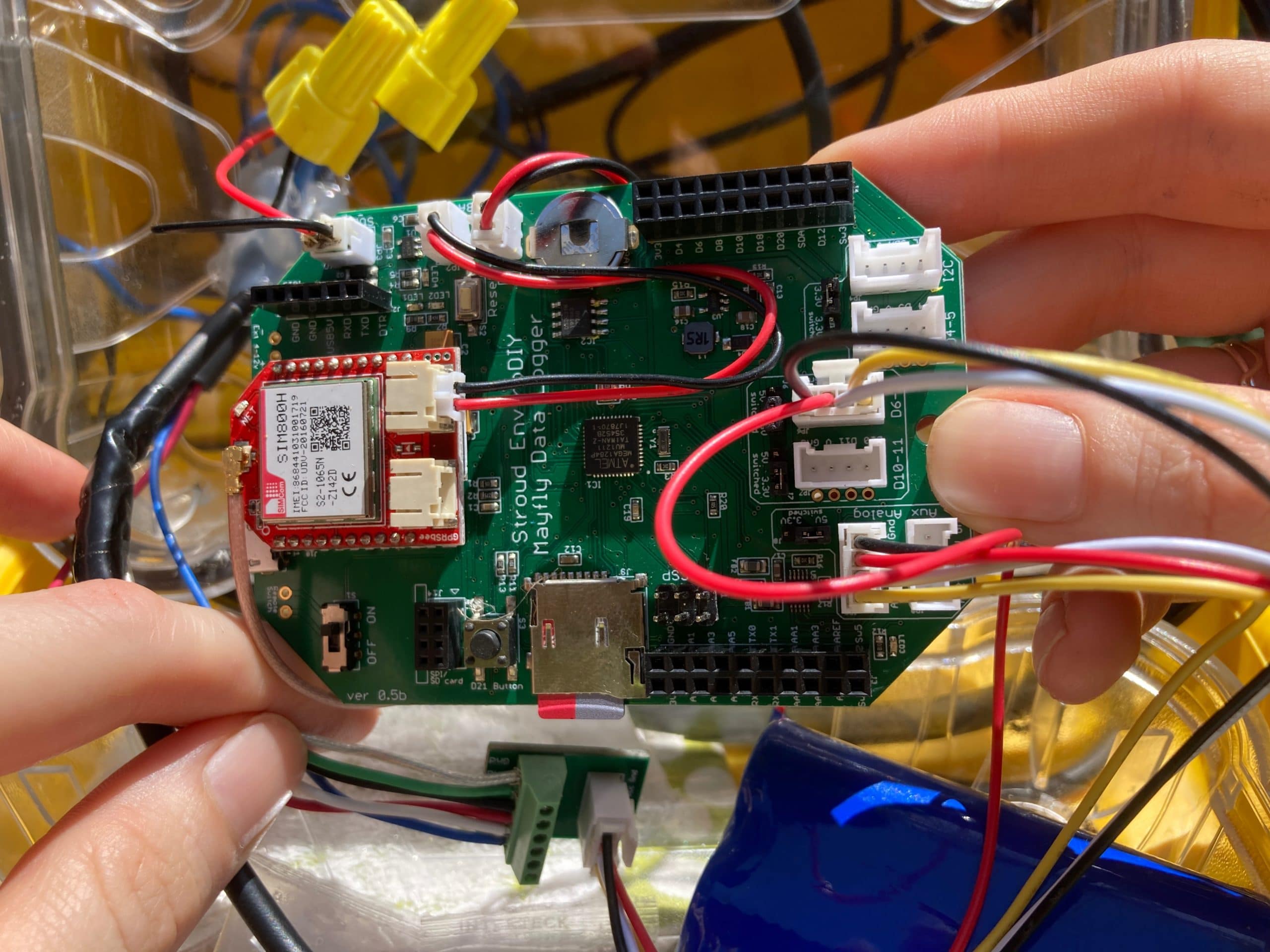
Is the small jumper on the Mayfly board next to the Aux Analog grove ports switched over to 5v from it’s default 3v position? Did you verify that all of the sensor wires are connected to the right ports on the 6-pin screw terminal board? Red wire to Vcc, White wire to D2, Blue wire to D1, and the other three wires (black, green, and clear) all go to GND? And that the grove cable is connected to the AA0-AA1 port on the Mayfly? Do you see the red LED3 come on next to the Aux Analog ports when you’re taking a sample?
You can also post a photo of the Mayfly board and the sensor wiring on the screw terminal board if you can take a nice, focused photo.
-
2020-09-21 at 4:42 PM #14591
It turns out that I had had wires of the OBS3+ in the wrong screw terminals. Rewiring the high and low turbidity readings within a reasonable range. The problem now is that the sensor is not reading accurately. High turbidity always reads about 3 NTU and low turbidity always reads about 1 NTU. I have measured with two handheald turbidity meters and they were both reading 11-12 NTU. I checked and the grove cable is connected to the AA0-AA1 terminal and the aux analog port is switched from 3V – 5V. I’ve attached a photo of my wiring. Thanks!
Attachments:
-
2020-09-21 at 10:08 PM #14594
It sounds like the sensor isn’t getting power. Do you know which sensor wire you had plugged into the Vcc jack on the screw terminal board? Do you have a voltmeter (multimeter) that you could put on the Vcc line to measure the output voltage of the Mayfly’s 5v switch boost circuitry when the sensor is supposed to be powered for a sample? It’s likely that connecting the sensor wires to the wrong terminals damaged the circuit on the Mayfly board that generates the 5-volt power, or the sensor itself might have been damaged.
-
2021-04-09 at 9:40 AM #15368
#jsterling, I am looking for OBS3+ for my pilot project , went to campbell site but it shows discontinued. Can any support to provide source for OBS3+ or its alternate model
-
2021-04-09 at 10:01 AM #15369
Campbell Scientific discontinued the OBB3+ sensor about a year ago. They have new turbidity sensor models in development, but I’ll let them make the announcement about when it will be ready.
-
-
2021-04-09 at 10:10 AM #15370
Thanks , can you suggest alternate of any other company having almost same specs
-
2021-04-09 at 2:51 PM #15371
There’s not a direct replacement for that sensor, meaning one with the same operating specs and output. There are some alternatives, but most are significantly more expensive, or require different interface hardware (like the Yosemitech sensors), or Turner Cyclops sensors (but require user calibration). Unless you need a turbidity sensor immediately, I’d recommend waiting just a little bit longer and there will be some good sensor options unveiled soon.
-
-
2021-04-13 at 3:56 AM #15375
Hi @shicks. I need a number of turbidity sensors for an upcoming project, and I have a reasonable quote from Yosemitech (~510USD each). What additional interface hardware are you referring to for the Yosemitech probes? Has anyone tested them and can vouch for their accuracy?
-
2021-04-13 at 8:49 AM #15376
Those sensors use Modbus RS485 protocol to communicate with a host device, which the Mayfly logger can’t do natively do with its current hardware, so you’ll need to add either an aftermarket RS485-to-TTL interface board, or build one like Anthony (@aufdenkampe) has done. He, and a few other people on the forum, have deployed some Yosemitech sensors for quite awhile and should be able to provide some feedback about their performance.
-
-
2021-04-13 at 11:33 AM #15377
I’ve been working on a next revision board. Details at https://github.com/neilh10/SensorModbusMaster/tree/release1/hardware/knh002-MayflyWingShield
overview at https://github.com/neilh10/SensorModbusMaster/tree/release1/hardware
I don’t have any time frame on availability due to the world wide shortage of parts, but probably third quarter this year. It will be an order before hand build so good timing if you are thinking of getting some.
I have hand built some for testing, and now have them testing on a system with a Keller Acculevel /0.28.3
I’ve got it on my list to do more write up.
-
2021-04-13 at 5:08 PM #15382
Thanks @neilh20. I will definitely be interested in these when they are available.
@aufdenkampe do you have any feedback about YOSEMITECH turbidity sensors? My questions are:1) Are they as reliable as other turbidity sensors, i.e. do they drift more readily, or provide strange values? For $510USD (non-wiper) or $680USD (wiper), they seem like a good deal.
2) Is it worth getting the wiper version over the non-wiper version?
3) We have a YSI multi-sonde deployed for another project using a modbus wing. Our technicians noted that the wiper powers on every-time the Mayfly connects to the probe, draining the battery. Is this the same for the YOSEMITECH sensors or is there a way around this?
3) How much does the RS485-to-TTL interface board cost to build?
Thanks for your help.
James
-
2021-05-21 at 9:55 AM #15556
James, I really like all the YosemiTech sensors I’ve used, and I’ve facilitated the purchase of approximately ~150 or more for various organizations. The Y511 turbidity sensor with wiper is the most common we use, and everyone is very satisfied with it.
I’ve been working with a water utility, and after doing a careful comparison with their other commercial sensors, they decided to purchase an additional 60 sensors for YosemiTech.
To answer your specific questions:
- Yes, YosemiTech sensors have equivalent data quality to the major brands of commercial water quality sensors.
- Get the sensor with the wiper, always for long-term deployment. I would only get the one without a wiper if I were building “hand meter” sensor system for spot checking.
- The Modular Sensors code on the Mayfly turn off power to sensors between measurement intervals (to save power). The YosemiTech sensors with wipers all spin the wiper each time it is powered on, and I suspect the YSI does the same. You can reconfigure the wiring and the code to do this differently if you want. Brushes definitely require more power, but it is very important to do regularly. That said, I have no problem deploying a YosemiTech turbidity sensor with a 2 W solar panel and a 4400 mAh battery and taking measurements every 15 minutes.
- The DIY Modbus-Mayfly_WingShield costs about US$ 35 in parts and ~1 hour to solder together. The new manufacturable version by @neilh20 costs a bit more than that but no labor (see https://www.envirodiy.org/topic/testing-ttl-rs485-adapters/#post-15553).
-
2021-05-23 at 9:41 PM #15564
Thanks Anthony! I’m feeling a lot more comfortable about Yosemitech sensors now that I have a test unit in my hands. I can’t wait to get them out in the field.
James
-
-
AuthorPosts
- You must be logged in to reply to this topic.