
Home › Forums › Mayfly Data Logger › Testing TTL-RS485 Adapters
- This topic has 8 replies, 3 voices, and was last updated 2021-05-24 at 11:27 AM by
 Anthony Aufdenkampe.
-
AuthorPosts
-
-
2021-05-20 at 7:31 PM #15551
Hi all,
I am going the the process of building 10 x modbus wings for Yosemitech sensors. Most people are probably aware of the lack of quality control on these adapters, so I would like to test them before I solder them to the wing. What is the best way to test one of these without soldering to the wing headers? I tried just sliding one over the pins but the connection doesn’t seem to be through the PCB hole.
James
-
2021-05-20 at 10:07 PM #15552
It depends on what kind of pinout is on the adapter board. I’m not familiar with them since I don’t use them, but you could probably make a test jig with pogo pins, or if the boards have plated-through holes you can simply use male header pins and just hold the board at a bit of an angle to make contact.
-
2021-05-21 at 9:38 AM #15553
James, we’ve been playing with hardware designed for this for quite some time (as a subfolder in our SensorModbusMaster repo), and just recently spun our commits/designs into it’s own Mayfly-Modbus-Wing repo. Have you seen this?
Our solder-your own DIY version is described here: https://github.com/EnviroDIY/Mayfly-Modbus-Wing/tree/master/Modbus-Mayfly_WingShield
Meanwhile, @neilh20 designed a much improved manufacturable variant that we’re getting made now. It’s shown below and described here:
https://github.com/EnviroDIY/Mayfly-Modbus-Wing/tree/master/knh002-MayflyWingShield.We have some work to do on improving documentation, but hopefully this will all be helpful.
Attachments:
-
2021-05-21 at 9:41 AM #15555
James, by the way, I would suggest that you NOT solder anything to the wing headers. Our two options just plug into them and can be removed anytime, just like an Arduino shield.
-
2021-05-21 at 4:04 PM #15558
Hi @shicks. Thank you. I was considering pogo pins. I assume you just solder them in and push the adapter board down to test? I guess I could also solder female headers into the wingshield holes and males into the adapter boards. This would allow me to test each adapter board on one rig, and I could just solder the male headers into new wing shield boards once I have confirmed they work.
@aufdenkampe thanks for the info. Neil is doing some amazing things but I have a short timeframe to deploy 10 sites, hence I am opting for the DIY approach. Also, our electrical technician had around 40 PCBs printed by DFRobot, so I have most of the DIY components at my fingertips. I just have to wade through the unreliable adapter board issue.I’m not sure what you mean regarding not soldering anything into the wingshield. The TTL RS485 adapter seems to be soldered to the wingshield in the image below?
FYI I have had success talking to my Y511-A turbidity sensor. Do you know if the issues with the brush interval have been fixed, I.e can you set the brush interval to save power, or does it just default to every time the board fires up?
James
Attachments:
-
2021-05-21 at 6:55 PM #15560
James, I’m glad to see that you’re using our DIY Mayfly-Modbus-Wing. Yes, soldering the DIY windshield is required. I had thought you were discussing soldering an RS485 adapter directly to the Mayfly. My bad for misunderstanding!
From my perspective, there is not “problem” with the YosemiTech Y511 turbidity brush running every time the sensor wakes up to take a measurement. You might have read of some issues back in 2017, but since we massively improved power management shortly after that (via ModularSensors improvements), we have had no power problems.
-
2021-05-22 at 9:43 PM #15561
Hi @aufdenkampe,
That’s really good news. Yes I was reading through some historical issues on git-hub about problems with the Polou step-up module and inability to set brush intervals. My 511-A seems to be functioning well so I’m assuming the Polou step-up issue is also solved.
One quick question, In your view, is the 511-A worth the extra money over the 510-B?
Edit: I also need to thank you for the 120 ohm resistor trick. So far I have tested four TTL-RS485 adapters and all of them required a 120 ohm resistor to function properly. They all work with that slight mod though!
James
-
2021-05-23 at 4:44 AM #15562
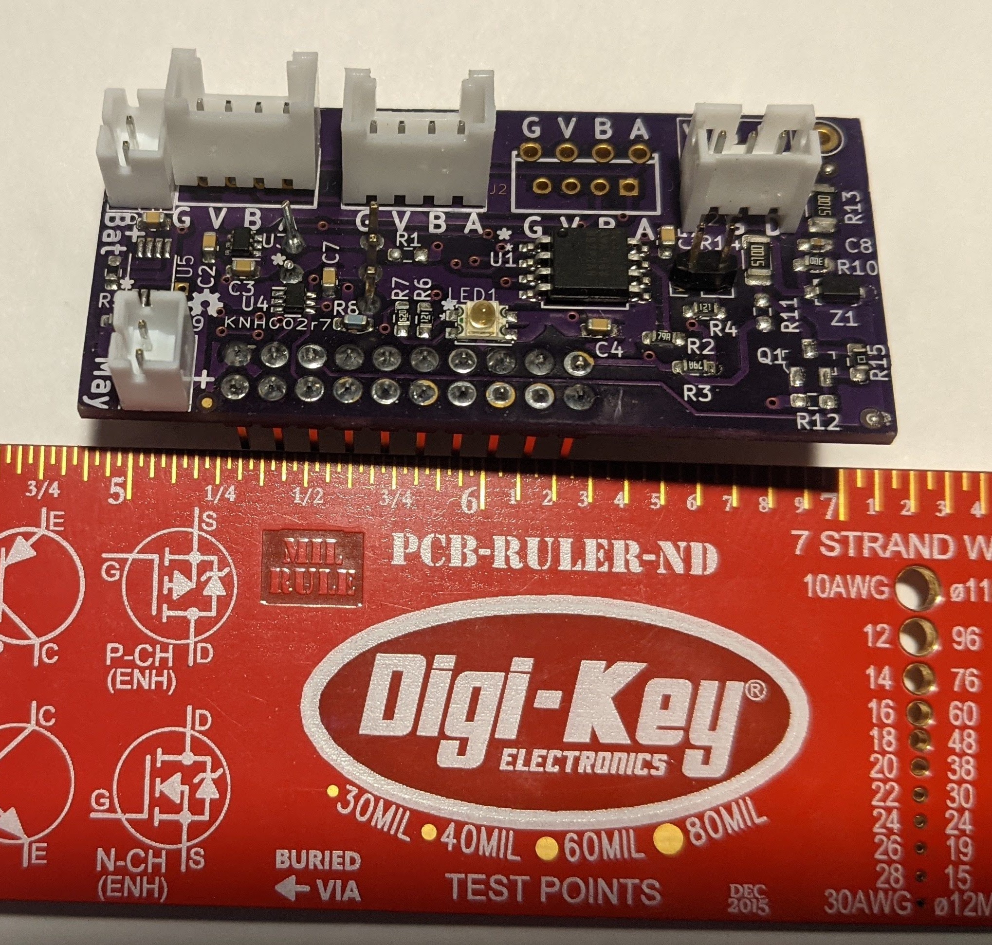
Also, for anyone who is interested. My solution to testing multiple TTL-RS485 adapters with one rig can be seen in the attached photo.
James
Attachments:
-
2021-05-24 at 11:27 AM #15567
@james-dareboprc-govt-nz, those power issues you came across on GitHub (regarding getting the brush to spin and wondering about setting the spin rate) were quite old (2017?) when we first started using YosemiTech sensors and early in my knowledge of DIY electronics. The short-story is that once we figured out that we needed to add a capacitor (i.e. powering a device wasn’t just about voltage), then we had no problems.
I strongly urge you to get the Y511 turbidity sensor with the auto-brush/wiper. Otherwise you will be seeing sensor drift within a week or so (depending on the season) and will need to manually clean your sensor. The extra US$150 is definitely worth it. More details here: https://www.envirodiy.org/topic/problems-with-obs3/#post-15556
I like your solution for testing the RS-485 adapter boards from China before soldering them onto a Mayfly-Modbus-Wing.
By the way, when I have found a RS-485 adapter board that doesn’t work, I have solved the issue 14 out of 15 times by soldering on a 120 ohm resistor (1/4 W) directly to the A+ and B- terminals on the RS-485 adapter, as I showed and described here: https://github.com/EnviroDIY/SensorModbusMaster/issues/14#issuecomment-678554101
-
-
AuthorPosts


- You must be logged in to reply to this topic.