
Home › Forums › Mayfly Data Logger › Could not wake modem for clock sync
- This topic has 12 replies, 4 voices, and was last updated 2025-11-18 at 6:03 PM by
Tom Clark.
-
AuthorPosts
-
-
2024-10-10 at 3:35 PM #18682
Hi,
Continuing to run into a problem connecting our Mayfly to LTE, getting an error: “Could not wake modem for clock sync”.
I’ve seen this posted a lot but I still can’t find any concrete reasons as to why I’m getting this error. I’m using the “DRWI_SIM7080LTE” sample sketch and using a HYDROS 21 to connect.
I’ve generated, formatted, and connected all the appropriate UUIDs according to Monitormywatershed, and the serial clock monitor is saying that they’re all in a logical order. I’m also able to save data and it seems the sensor is working, it’s just giving me -9999 for connectivity to LTE and just not able to wake up the modem in general.
Some other info:
Using the SIM7080G, and the part of the sketch that corresponds is as follows:
/** Start [sim_com_sim7080] */
// For almost anything based on the SIMCom SIM7080G
#include <modems/SIMComSIM7080.h>// Create a reference to the serial port for the modem
HardwareSerial& modemSerial = Serial1; // Use hardware serial if possible
const int32_t modemBaud = 9600; // SIM7080 does auto-bauding by default, but
// for simplicity we set to 9600// Modem Pins – Describe the physical pin connection of your modem to your board
// NOTE: Use -1 for pins that do not applyconst int8_t modemVccPin = 18;
// MCU pin controlling modem power — Pin 18 is the power enable pin for the
// bee socket on Mayfly v1.0, use -1 if using Mayfly 0.5b or if the bee socket
// is constantly powered (ie you changed SJ18 on Mayfly 1.77u
const int8_t modemStatusPin = 19; // MCU pin used to read modem status
const int8_t modemSleepRqPin = 23; // MCU pin for modem sleep/wake request
const int8_t modemLEDPin = redLED; // MCU pin connected an LED to show modem
//// Network connection information
const char* apn =
“hologram”; // APN connection name, typically Hologram unless you have a
// different provider’s SIM card. Change as needed// Create the modem object
SIMComSIM7080 modem7080(&modemSerial, modemVccPin, modemStatusPin,
modemSleepRqPin, apn);
// Create an extra reference to the modem by a generic name
SIMComSIM7080 modem = modem7080;
/** End [sim_com_sim7080] */Let me know if any other information is needed.
Thank you
-
2024-10-10 at 3:49 PM #18683
Also double checked hologram.io to check to see if the sim is active, it is. I’ve also tried swapping the battery out, taking the sd card in/out, and have messed around with
const int8_t modemVccPin = 18;
and have swapped it from 18 to -1 as per the commented code, but it has not worked.
-
2024-10-10 at 4:23 PM #18684
Does the red power light on the lower right of the modem turn on? If not, the modem isn’t getting power. Pin 18 should be the right pin number. I’m not sure why it wouldn’t be powering up. Have you ever messed with the solder jumpers?
If the modem is powering up, you might have a baud rate problem. Try setting the modemBaud to 57600 even 115200.
If neither of those work, then try dumping out debugging info. If you’re using PlatformIO, add this to your platformio.ini file within your default enviroment:
<div>
<div>INI123456build_flags =-D MS_SIMCOMSIM7080_DEBUG-D MS_SIMCOMSIM7080_DEBUG_DEEP-D MS_LOGGERMODEM_DEBUG-D MS_LOGGERMODEM_DEBUG_DEEP-D TINY_GSM_DEBUG=Serial</div>
</div>
If you’re using the Arduino IDE, add#define TINY_GSM_DEBUG Serialto the very top of your logging program. Then navigate to the ModularSensors folder within your libraries. In that folder, open up The ModularSensors folder, then the src folder. Open LoggerModem.h and remove the comment slashes from lines 27 and 28 (lines start with #define MS_LOGGERMODEM_DEBUG). The go into the modems subfolder, open SIMComSIM7080.h and remove the comment slashes from lines 47 and 48 ((lines start with#define MS_SIMCOMSIM7080_DEBUG). Save all of the files.Re-program your board with the debugging on and you should get lengthy print-outs about the modem communication. With that, I can better help find what’s wrong.
-
2024-10-10 at 4:32 PM #18685
Hi,
Thanks for the quick reply! I am not getting any red lights on the modem at all. I have the Mayfly plugged into my pc right now and the only lights are the orange charge light, the USB/POWER lights, and D8 is lit up as green right now.
The modem seems to be correctly seated according to the instructions. We previously were able to get this logger working before with a Clarivue10 but we ran into a bug where the logger eventually stopped saving anything to the sd card + wasn’t uploading to monitormywatershed, but it seems to be saving fine to the sd card with the Hydros 21 currently, only the LTE is not working.
I will work on getting the debugging info and get back to you.
Thanks so much,
Elliot
-
2024-10-10 at 10:00 PM #18688
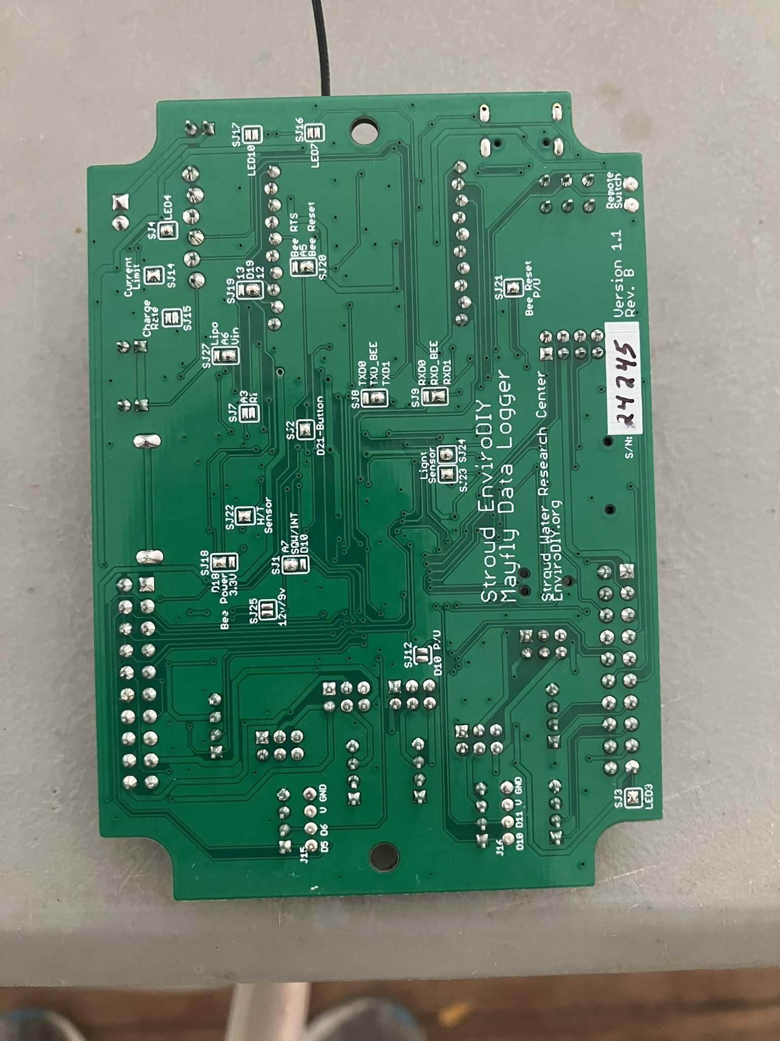
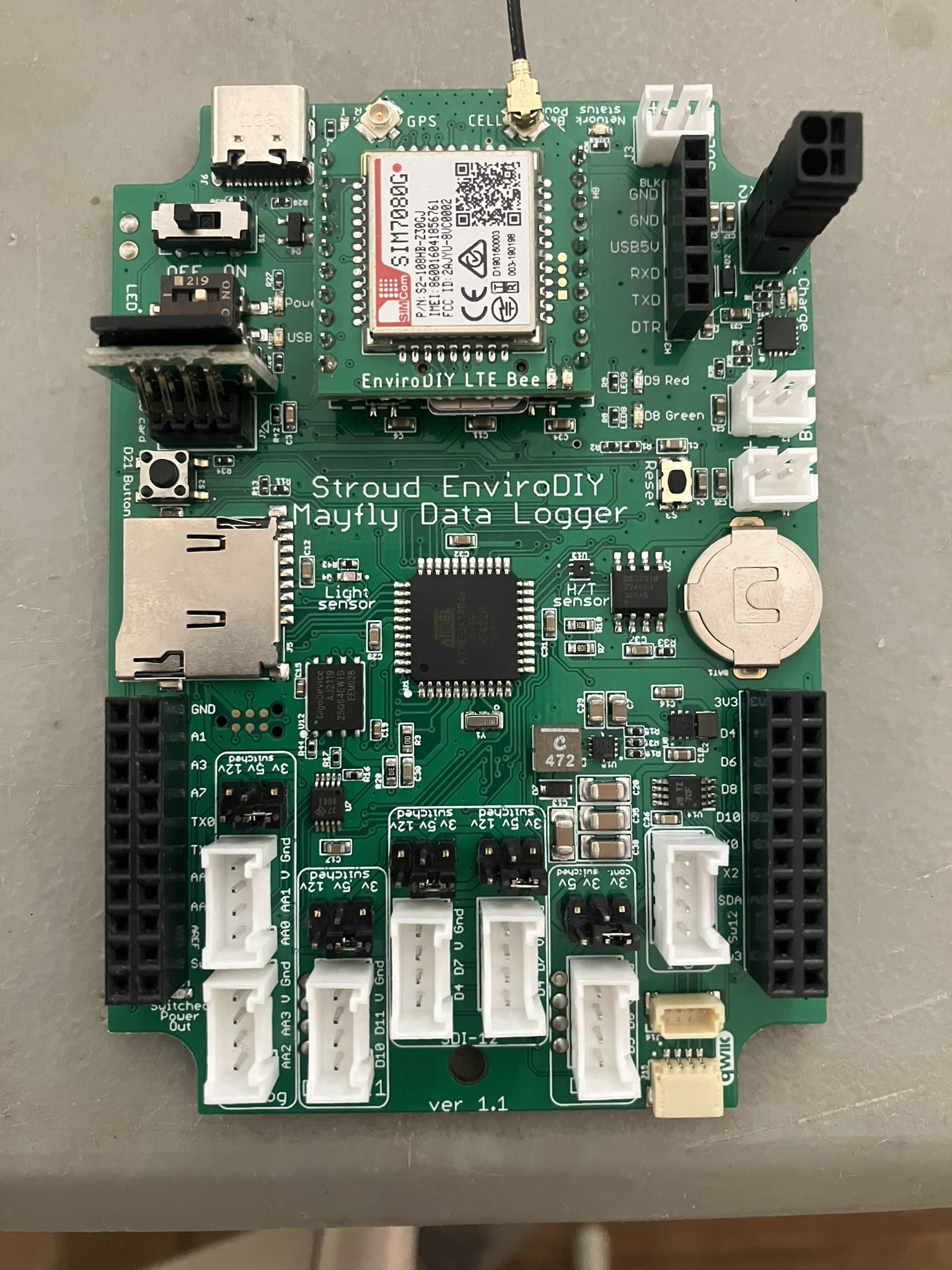
Can you email me the entire .ino sketch that you’re using with the board, and also a clear, in-focus photo of the back of the Mayfly board, and the front of the Mayfly board, with and without the LTEbee attached.
-
2024-10-15 at 11:55 AM #18699
Hi Shannon and Sara,
Thanks for taking a look at this. I actually JUST fixed it, and I’m not sure what I did correctly?
Nothing I did was able to wake the modem, and like Sara said, it wasn’t receiving power. I was in the midst of taking those photos you request Shannon, and I think just unplugging everything and plugging it back in fixed it… I’m very embarrassed haha.
Thank you guys anyway!
Elliot
-
2025-09-26 at 2:47 PM #19378
Hi Sara and Shannon,
I am also getting the “could not wake modem for clock sync” error. I do not know if it’s connected but when the logger records to the SD card (after giving the “could not wake modem for clock sync” error) it records at random time intervals and only takes a few data points before stopping.
Here is the debugging information I got after changing lines 27 and 28 in LoggerModem.h and lines 47 and 48 in SIMComSIM7080.h:
Now running Narbrook.ino on Logger Narbrook ParkUsing ModularSensors Library version 0.36.0
TinyGSM Library version 0.12.0Logger timezone is set to UTC -5
RTC timezone is set to UTC
Current RTC time is: 2025-09-26T17:53:48-05:00
Current localized logger time is: 2025-09-26T12:53:48-05:00
All variable UUID’s appear to be correctly formed.fbc4f0bf-4f16-4110-8da1-a1f547709911 -> Hydros21cond
53a2618d-7ec7-427d-84fb-7bc9dc0795c7 -> Hydros21depth
11679e79-20c2-4a89-ace6-6193aec2bd80 -> Hydros21temp
a6eecc3b-c427-4d17-b9a1-e81d82ef0c35 -> Battery
7d9e2dfc-69aa-4d62-806e-ac94d576fe13 -> BoardTemp
8701fa74-2285-4c90-90c4-4fe84fa3d0db -> signalPercentThis logger has a variable array with 6 variables, of which 5 come from 3 sensors and 1 are calculated.
Sampling feature UUID is: 872ca3da-3b97-460b-abc9-e5b18b073627
Data will be published to [ 0 ] monitormywatershed.org/api/data-stream/
Logger portion of setup finished.Setting up sensors…
Waking modem and setting Cellular Carrier Options…
Initializing pin 19 for modem status with on level expected to be HIGH <–LoggerModem
Initializing pin 23 for modem sleep with starting value HIGH <–LoggerModem
Initializing pin 20 for modem reset with starting value HIGH <–LoggerModem
Initializing pin 9 for modem status LED with starting value 0 <–LoggerModem
Power to unspecified modem is not controlled by this library. <–LoggerModem
Doing a hard reset on the modem by setting pin 20 LOW for 5 ms <–LoggerModem
Setting up the modem … <–LoggerModem
Modem was already awake and should be ready for setup. <–LoggerModem
Running modem’s extra setup function … <–LoggerModem
… setup failed! It’s a Digi XBee Unknown <–LoggerModem
Digi XBee Unknown warms up in 100 ms, indicates status in 15 ms, is responsive to AT commands in less than 15000 ms, and takes up to 15000 ms to close connections and shut down. <–LoggerModem
Leaving modem on after setup … <–LoggerModem
Wait while applying changes…
Attempting to connect to the internet and synchronize RTC with NIST
This may take up to two minutes!
Doing a hard reset on the modem by setting pin 20 LOW for 5 ms <–LoggerModem
Doing a hard reset on the modem by setting pin 20 LOW for 5 ms <–LoggerModem
Setting up the modem … <–LoggerModem
Modem was already awake and should be ready for setup. <–LoggerModem
Running modem’s extra setup function … <–LoggerModem
… setup failed! It’s a Digi XBee Unknown <–LoggerModem
Digi XBee Unknown warms up in 100 ms, indicates status in 15 ms, is responsive to AT commands in less than 15000 ms, and takes up to 15000 ms to close connections and shut down. <–LoggerModem
Leaving modem on after setup … <–LoggerModem
Could not wake modem for clock sync.
Turning Digi XBee Unknown off. <–LoggerModem
Putting Digi XBee Unknown to sleep. <–LoggerModem
Running given sleep function for Digi XBee Unknown <–LoggerModem
Power to Digi XBee Unknown is not controlled by this library – not waiting for shut-down to complete. <–LoggerModem
Setting up file on SD card
Data will be saved as Narbrook Park_2025-09-26.csv
Putting processor to sleepThe .ino file, photos of the front of the logger with and without the LTE bee, and the back of the logger are attached.
Let me know if any other information would be helpful.
Thank you!
Tom -
2025-09-26 at 2:56 PM #19383
What sketch are you running? The debug statements above are mentioning Digi Xbee module, but your photo shows a Simcom SIM7080 module. The code for a Digi Xbee modem is not compatible with the Simcom module shown in the photo.
If you’re trying to use the configuration shown in the photo, along with a Hyrdos 21 CTD sensor (as indicated in your code above) then you should be using the example sketch we wrote for this exact configuration: https://github.com/EnviroDIY/ModularSensors/tree/master/examples/DRWI_Mayfly1
-
2025-10-30 at 11:54 AM #19420
Thank you! After switching to the correct sketch I am getting an error saying “logger clock has not been declared”
-
2025-11-01 at 6:13 PM #19422
That sounds like there’s probably an error in your code that is causing one or more missing functions calls to give an error when compiling. Have you tried compiling the example sketch exactly as it’s written on that github page I linked above, with no edits at all? If you’re successful in compiling that example, then compare your edited sketch to the example line-by-line and see what’s causing the error.
-
-
2025-11-05 at 6:36 PM #19425
Thank you for the response. I tried without sketch without making any changes and got the same error:
/Users/tom/Documents/Work/sketch_nov5a/sketch_nov5a.ino: In function ‘void setup()’:
/Users/tom/Documents/Work/sketch_nov5a/sketch_nov5a.ino:326:5: error: ‘loggerClock’ has not been declared
loggerClock::setRTCOffset(0);
/Users/tom/Documents/Work/sketch_nov5a/sketch_nov5a.ino:365:40: error: ‘loggerClock’ has not been declared
if (getBatteryVoltage() > 3.55 || !loggerClock::isRTCSane()) {
exit status 1
Compilation error: ‘loggerClock’ has not been declared -
2025-11-06 at 9:33 AM #19426
It sounds like you don’t have all the correct library files installed in your Arduino/libraries folder. How many sub-folders do you have in that directory on your computer? When did you last download the ModularSensors library dependency files?
-
2025-11-18 at 6:03 PM #19433
I downloaded again today and it did not work. There are 47 sub folders in the directory. Maybe I am using the wrong link like I was with the sketch. I got the library from here https://github.com/envirodiy/libraries?tab=readme-ov-file
-
-
AuthorPosts

- You must be logged in to reply to this topic.