
Home › Forums › Mayfly Data Logger › Campbell Scientific CS-215 SDI-12 communication issues w/ Mayfly
Tagged: SDI-12 YSI EXO
- This topic has 27 replies, 6 voices, and was last updated 2020-12-04 at 3:09 PM by
 Sara Damiano.
-
AuthorPosts
-
-
2018-04-30 at 2:21 PM #12273
Hi everyone,
We have made some good strides getting a Mayfly logger network started here in New Hampshire thanks to all the information here on Enviro-DIYs forums. We can now collect measurements from multiple SDI-12 devices, store to an SD card, connected to a battery and RTC for sleep when not collecting.
We’ve been thinking about adding a Campbell Scientific CS-215 (link) using a power relay and an external battery to provide it with 12V. There seems to be an issue connecting the Mayfly to the CS-215 though. We are able to provide it with an address using the address_change.ino script in the Envirodiy/SDI-12 examples. However, when we attempt to scan for addresses, the sensor is not found.
The interesting thing is that when we use a Campbell Scientific Logger to communicate with the sensor, everything seems fine. That is leading us to think that there is an issue with the delay or timing in the script for the arduino-based logger. I’ve seen some others with this kind of issue (example) but have not been able to find a solution.
I wonder if anyone here may have a thought about what could be the issue?
Dave
-
2018-04-30 at 4:05 PM #12275
Hm. I’ve done some pretty extensive rewriting of the sdi-12 library in the last month or so. Do you know which version of the library you are using? Can you try updating to the most recent version (1.3.1) if you’re not already using it? Can you post the full serial output your getting from both the address change example (b) and the data logging example (d).
-
2018-05-03 at 11:18 AM #12287
Hi Sara,
Thank you for getting back to me. I’ll check the version of the library we have and will capture the serial output. We won’t be having a lab meeting until Tuesday so I will send it right after that. I noticed that there were updates last month so perhaps that will sort things out. In the meantime, thank you for helping!
Dave
-
2018-05-08 at 6:24 PM #12288
Hi Sara,
We spent several hours today trying to work with the CS-215. We did update and use the most recent library (1.3.1) but were still having issues with the two examples. For the address change example, all of the addresses were vacant, even though we had defined the sensor having an address previously using a CR1000 (Campbell) logger. The simple logger did not result in anything going to the serial – it said no sensors found and to check the physical connection.
One interesting twist – for a while we were adjusting the delays in the address change script with the original (1.0.1) library. Every time the code ran, the sensor appeared at an address and we were able to change the address. However, when the script continued and rescanned all the addresses, the sensor was identified in a different address than what we told it to be at. This makes me think that there is some particular mismatch between the timing and delays that the sensor requires when passing data back/forth using the SDI-12 protocol, and what is in the library that works with other sensors that are not 12 volts.
The only thing we can think of is that somewhere in the CS code for how a CS logger interacts with a CS-215 that gets the delays exactly right because Campbell knows the timing needed by that particular sensor. I’m not sure if it is possible to access that script and/or look in the manual to see if it is an issue with the specific sensor, but that is my guess. You may know where to look since you were involved in working with that library?
Here is the manual
Thanks for any advice or guidance you could provide,
Dave
-
-
2018-05-09 at 9:22 PM #12289
Hm. I doubt the mid-character times are the problem, but it is possible that the break or marking times are causing problems. You can try tweaking them a bit on the very top of the SDI12.cpp file.
Instead of timing, it’s possible there’s a voltage problem. Do you have the sdi-12 data pin going directly to the Mayfly? Then the power and ground to another battery? The sdi-12 specification actually requires that the voltage of the “spacing” be over 3.5V. The Mayfly is only powered at 3.3V, so it’s not actually ever getting the voltage high enough to meet sdi-12 specs. The decagon and zebra tech sensors I’ve worked with have seemed to be fine with that but the Campbell might not be. Can you try putting a level shifter on the data pin to boost the voltage? I think a standard Uno runs at 5V so you could also try the basic communication on an Uno if you have one handy to see if it works.
-
2018-07-23 at 5:19 PM #12328
Sara,
Just to loop back – we were in touch with Campbell and their suggestion was also along the lines of the 3.5V voltage requirement. In the meantime, we picked up a Meter Group (formerly Decagon) ATMOS-14 sensor which collects temp/RH/VP and it worked perfectly. Since we only had to install one, we just went with that.
We’ll try to figure this out this fall/winter and once we do, I’ll make sure to update this thread for others!
Dave
-
-
2018-05-09 at 9:28 PM #12290
I’m sorry, I just looked back at your link from the first page and they mentioned they were using a Mega, which should be 5V. I don’t know. I don’t have any other guesses. Do you have an oscilloscope you can put on the line to watch the communication between the sensor and CR1000? If so, can you share the results of sending a single command to the sensor via the CR1000 and the same command between the Mayfly and sensor?
-
2018-10-03 at 5:35 PM #12569
Hi everyone,
Just an update here. Due to the issues with the CS-215, we ultimately decided to go with the Meter Group’s ATMOS-41. It worked seamlessly with the Mayfly and our script and we had no issues with addresses or voltages. Seeing that it was relatively similar in cost, it was an easy decision. This evades the answer to the question, so this won’t be of help to those looking for how to use a CS-215 they may have lying about, unfortunately.
Dave
-
2019-02-14 at 10:50 AM #12787
Dave,
Just curious if you ever revisited this issue over the winter? I am having the exact same issue with a Viasala WXT530 and YSI EXO. I did find a post where I guy successfully got his WXT530 to work back in 2017 (https://hankpai.weebly.com/sandbox/arduino-data-logger-vaisala-some-code). We are powering the devices with 9V and able to change the SDI-12 address of the WXT, but can’t get the SDI12_b_address_change program to find the device or get any response from the sensors. I also tried using a sparkfun logic level converter (https://www.sparkfun.com/products/12009), thinking the WXT530 signal is too high since it is powered by 9V, but I couldn’t even change the SDI address with the converter. I am using the 19.3 modular sensors library for my test.
-
2019-02-18 at 2:25 PM #12801
Greg,
We never revisited the issue and instead just gave the address to the CS-215 via a CS logger. I know that our team installed an ATMOS-14 at the site, and got around power issues by just powering the sensors separately from the Mayfly board by using DIN rails. It really seems that the different power requirements between the board and the sensors don’t allow for easy address updating and connections.
That said, I am also working on a project where we are going to be using some hydrological sensors and making sure that the Mayfly will work with a YSI sonde is pretty important. I wonder if Sara may have more insights?
Dave
-
2019-02-18 at 5:49 PM #12802
We’ve used a Mayfly successfully with a variety of SDI-12 sensors from different manufacturers, including ones that require 9v or 12v excitation. I usually use a custom simple logic level converter with most of them, similar to the Sparkfun item Greg mentioned above. However the only ones that gave us problems were the YSI 6-series sondes, so I don’t have any tips for working with those.
-
-
2019-02-19 at 12:39 PM #12809
Thanks Shannon. Could you share the logic converter you have had success with? I like to give another logic converter a shot.
-
2019-02-22 at 11:44 AM #12811
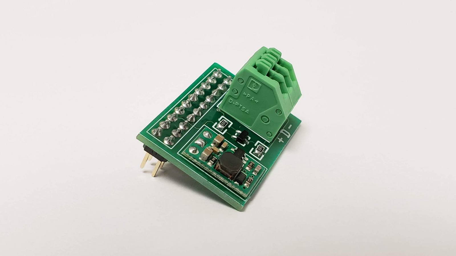
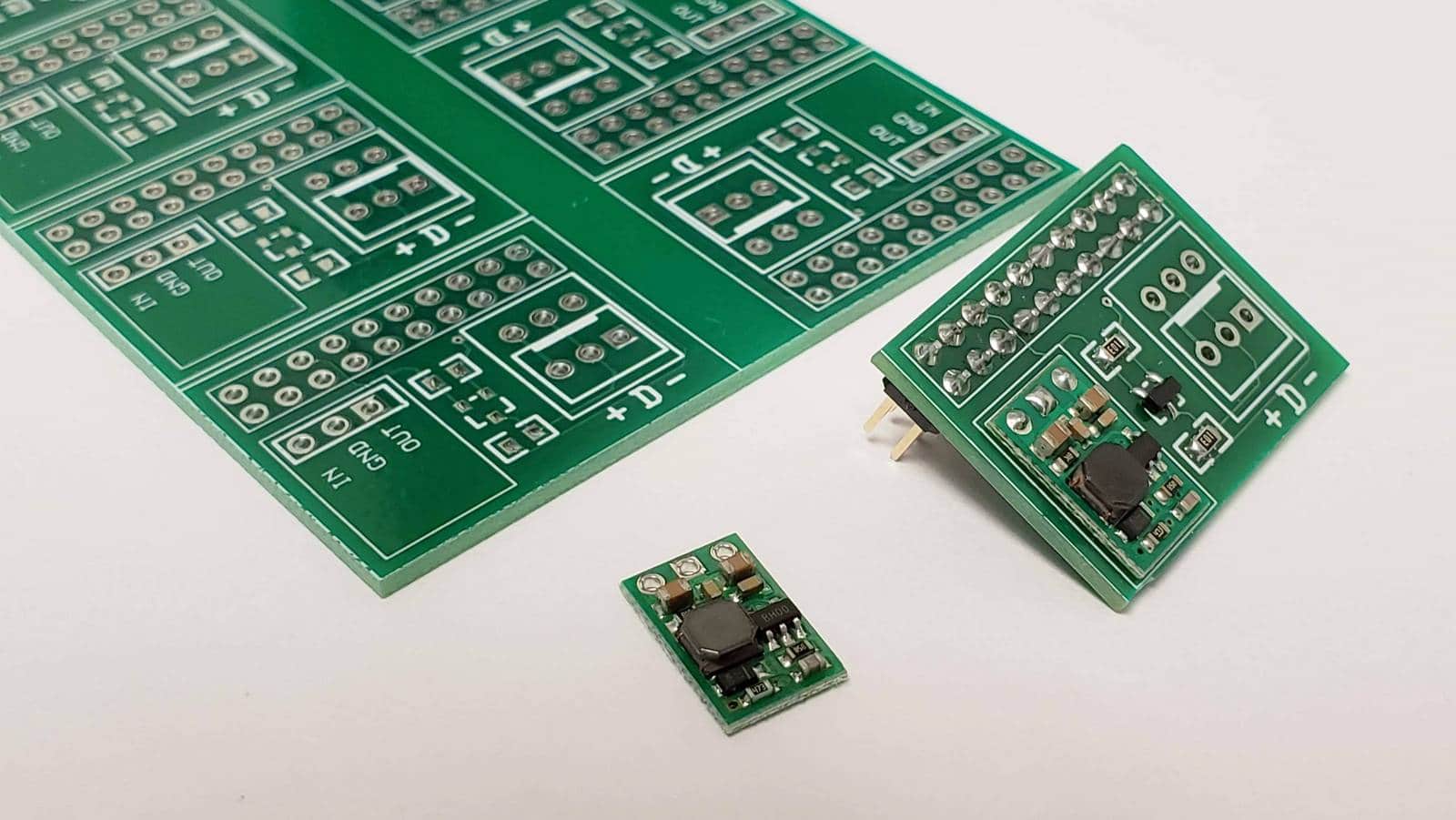
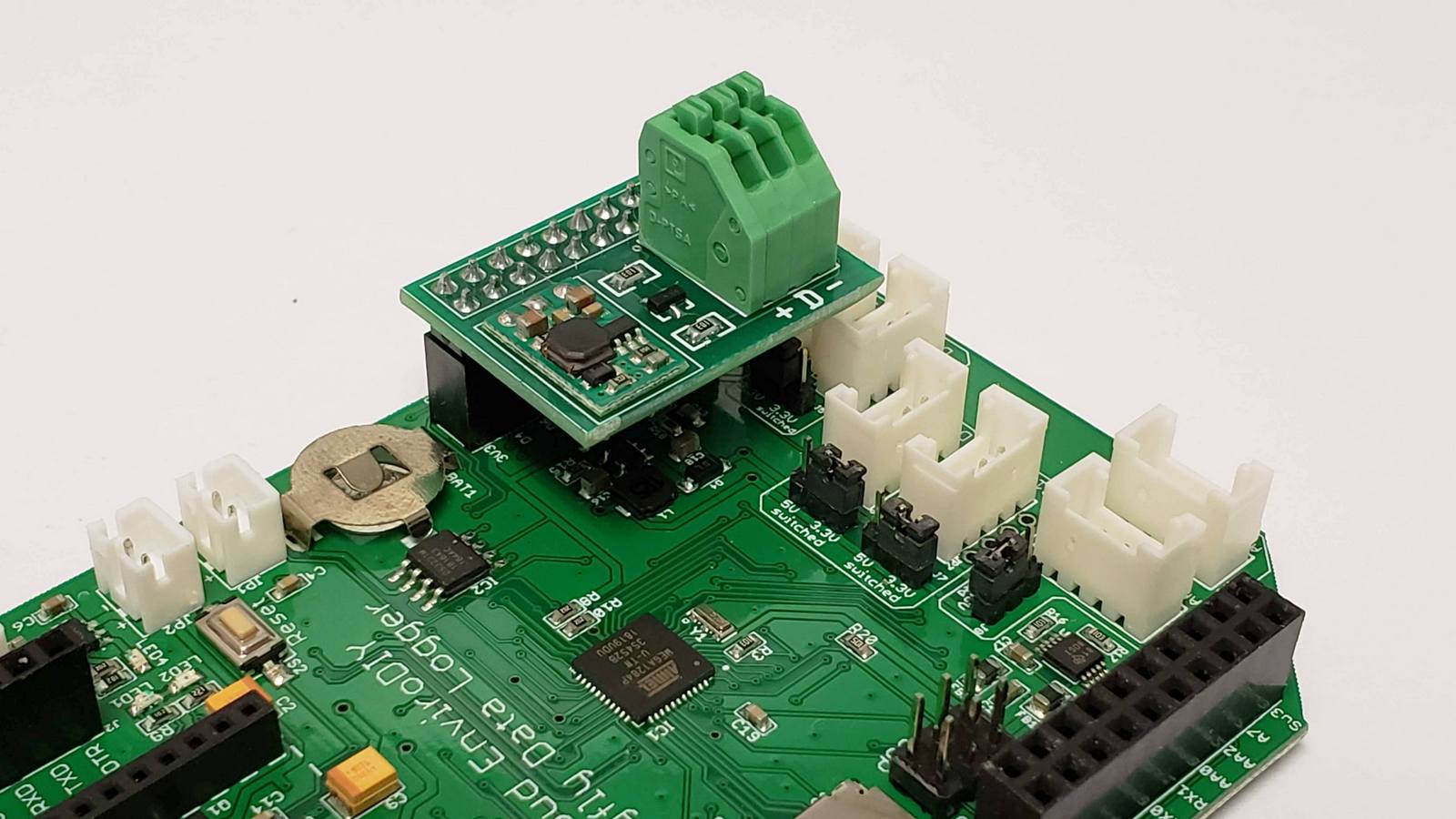
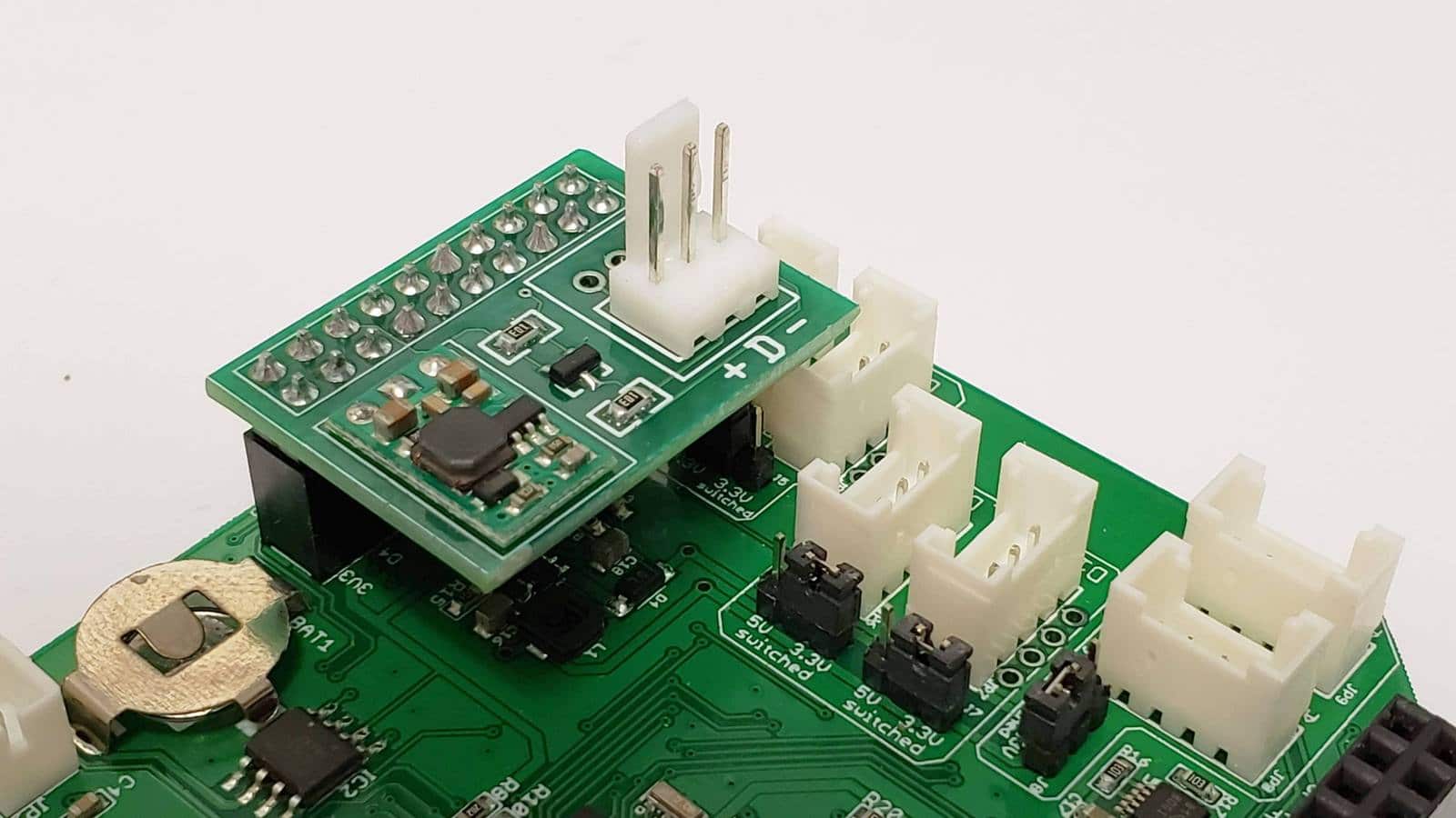
I had one project recently that required more than 30 Mayfly boards where each would interface with one SDI-12 soil moisture sensor array that requires 9v excitation. So I drew up this little custom PCB (not in Eagle), had it printed, and assembled the boards myself. It’s essentially one channel of the Sparkfun level converter board mentioned above, using a BSS138 MOSFET and two resistors. I also added a spot for a 9v boost converter board (https://www.pololu.com/product/2116) which also comes in 5v and 12v versions. It requires cutting the boards apart on a band saw, and then the hardest part is hand-assembling the 3 SMD parts, but if you’ve got a steady hand and a hot-air rework station or oven, it’s easy. I used a 3-position spring-latch terminal block, but you could use screw terminals or Molex pins as shown in the other photos.
-
2019-02-25 at 2:08 PM #12827
Thanks Shannon! This is a clean way to implement a logic board to power converter! I have finally successfully retrieved and saved 18 values from our YSI EXO2, which itself requires a signal output adapter to transmit SDI-12, using the modular sensors library. This was done without using a logic converter and powering the EXO externally with 12V.
My initial error was not taking into account the pin interrupts for the mayfly (I first used the basic arduino sdi12 code) so I was able to send the message but that is why I was not receiving a message. For reference Arduino-SDI-12#variants-and-branches.
I have a working local header file for the YSI EXO and hope to commit the code and pull request in the next few weeks. I also found some limitations in the sdi12sensors library that need to changed to get more than 3 or 4 measurements from a sdi12 sensor. Once the sdi12sensors code is updated I would think any advanced instrument that produces many measurements via sdi-12 will be able to be used in a similar fashion as the YSI EXO header.
-
2019-02-25 at 11:12 PM #12829
The “base” (master) branch of the SDI12 library should claim all possible on change interrupts so you don’t need to mess with calling them yourself. You only need to define the interrupts if you work off the ExtInts branch or if you compile with a build flag to set SDI12_EXTERNAL_PCINT. I think the latter is only possible in PlatformIO. If you’re using an example PlatformIO configuration file from the ModularSensors library, you should see the build flag set there.
What changes needed to be made inside the sdi-12 library? Bigger buffer? Anything else?
-
-
-
2019-02-27 at 8:28 AM #12832
Unless you can make a large enough buffer to accommodate 20-30 values the full proof other option is to have a way a to check if the number of received values equal the number of expected from concurrent result command. If it doesn’t then increase the dataOption value from D0! to D1! and so on. I piggy-backed off your code SDI12Sensors code and simply said if we are beyond the third value and a -9999 is returned, then try increasing the dataOption and send command. This worked for me but isn’t the best method. Ideally the loop would center around the variables the SDI-12 device has, which you called ‘numVariables’ and not the number of variables the user sets ‘_numReturnedVars’. We could follow my logic for checking for more data after finding missing data (-9999) OR parse and count the results from the initial .read(), check if it is equal to ‘numVariables’, if not then ask for more data and append to previous results, and check again and so forth till read variables count equal the ‘numVariables’.
I also had to increase your sdiResponse.substring(4,5) to (4,6) to account for two digit variable counts.
C++123456789101112131415161718192021222324252627282930for (uint8_t i = 0; i < _numReturnedVars; i++){float result = _SDI12Internal.parseFloat();// The SDI-12 library should return -9999 on timeoutif (result == -9999 or isnan(result)) result = -9999;//Check if there are more values than in initial data commandif (i > 2 and result == -9999){// Empty the buffer again_SDI12Internal.clearBuffer();MS_DBG(getSensorNameAndLocation(), F("Checking for more data:"));String getDataCommand = "";getDataCommand += _SDI12address;getDataCommand += "D";getDataCommand += String(dataOption);getDataCommand += "!";dataOption += 1;_SDI12Internal.sendCommand(getDataCommand);delay(30); // It just needs this little delayMS_DBG(F(" >>>"), getDataCommand);while (_SDI12Internal.available() < 3 && (millis() - startTime) < 1500) {}MS_DBG(F(" Receiving results from"), getSensorNameAndLocation());_SDI12Internal.read(); // ignore the repeated SDI12 addressresult = _SDI12Internal.parseFloat();}MS_DBG(F(" <<< Result #"), i, ':', result);verifyAndAddMeasurementResult(i, result);}-
2020-12-04 at 3:09 PM #14878
I *finally* incorporated this when adding support for an InSitu RDO PRO-X. I started working on it and it took me a while to find where I’d talked about it before.
-
-
2019-02-27 at 6:02 PM #12833
@gregcutrell – The _numReturnedVars isn’t a “user set” variable in the typical way you might be thinking of it. It is *not* intended to be set by a user in a program. It’s intended to be set in the header file for a specific sensor. When creating it, the writer of the header file should know exactly how many values the sensor can and will return. Those lines are commented out because they really are only for debugging to confirm the sensor code works as it should.
But your code looks like it should be good. Can you put in a pull request?
-
2019-02-28 at 8:33 AM #12834
@saradamiano – I was going to bring up the _numReturnedVars issue when also doing a pull request for the YSI EXO. There are sensors out there, like the YSI sondes, where users typically set their own sdi-12 output so you can’t really create a header that has variables and variable counts set in there. It really needs to be done in the ino file. I’ve got the header working because I did the variable defines myself but it really needs to done in the ino file and carry over to the header file. I just wasn’t sure how to code it. I’ll tag you in github once I get the code in there for thoughts. Thanks
-
2019-02-28 at 1:02 PM #12835
I haven’t encountered those sensors yet. Hmmm..
-
-
-
2020-04-28 at 5:16 AM #14103
Hi,
As it seems the Enviro lib still have the same problem with the CS215, I think I actually found a fix, so i wanted to share it with you guys.
I’ve updated the Arduino thread linked in the first post. But I’ll put the same explanation here:
The Enviro lib does not fully respect the SDI-12 protocol. There is one important timing aspect which is completely missing from the lib. In the spec we can find the following statement:
“A sensor must wake up from a low-power standby mode and be capable of detecting a start bit from a valid command within 100 milliseconds after detecting a break”
In the Enviro library a SDI-12 command is directly sent after a wake up frame which is consisted of a 12ms spacing + 8.3ms marking (see sendCommand functions). I believe in most cases cases, sensors are implemented in such a way that they actually do wake up “just” after the detection of 12ms spacing (or not sleeping at all). The 8.3ms marking being more than enough time for them to wake up. The CS212 doesn’t seem to belong in that category. It takes A LOT of time for it to wake up (at least 60ms to consistently answer from what i have found out).
Adding (in my case) a 100ms delay, between a wake up frame and a SDI-12 command , as per requested in the spec, fixed the problem, for me.
Hope this can be helpful. If it is, I guess someone should update the lib =)
Have a good day, stay safe.
-
2020-06-18 at 10:58 AM #14255
Wow! That is amazing – and very helpful! I thought it may be an issue with a line in the library – we migrated to Meter group sensors which seemed to work – perhaps because of their ability to wake up more quickly.
-
2020-06-19 at 10:41 AM #14257
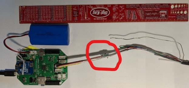
Looking at this posts as a discussion on general SDI-12, I have the Mayfly interface working for a Insitu LT500 Water Level monitor in a prototype capacity.
The LT500 requires an 8-36V Excitation, so I put in a series booster, +12V https://www.pololu.com/product/2117, and connected the other end to Grove 4pin JST-PH cable (std one cut in half)

I did use the standard SDI12 lib, and just created a header file for the InsituTrollSdi12.h for the interface. So very easy.Thanks for everyone contributing to SDI-12 to make it so easy.
I’d be happy to post back the InsituTrollSdi12.h if anybody wants.
It does take a little setup on the LT500 mapping the sensor value on polling to where the SDI12Sensors.cpp expects it – though my notes are a bit hazy on what I did.
Since the SDI-12 spec defines clamping excess voltages to ground (lightening/ESD), today I’m in the process of creating a true SDI-12 physical interface with the level shifter BSS138 ~ one side pluggable into a Grove 4pin/5V, and the other side taking the SDI-12 3wires.
Be happy to share the PCB/cct/BOM with anybody interested.
The target is to deliver the results over a Verizon signal ~ thanks to @mbarney for suggesting the Digkey SIM and data plan https://dataplans.digikey.com . It does require setting the apn to VZWINTERNET. Its not as easy as hologram to setup.
Attachments:
-
2020-07-10 at 2:27 PM #14308@nikeaulas What did you set the pin level to while you were waiting the extra time before the commands for the Campbell?
-
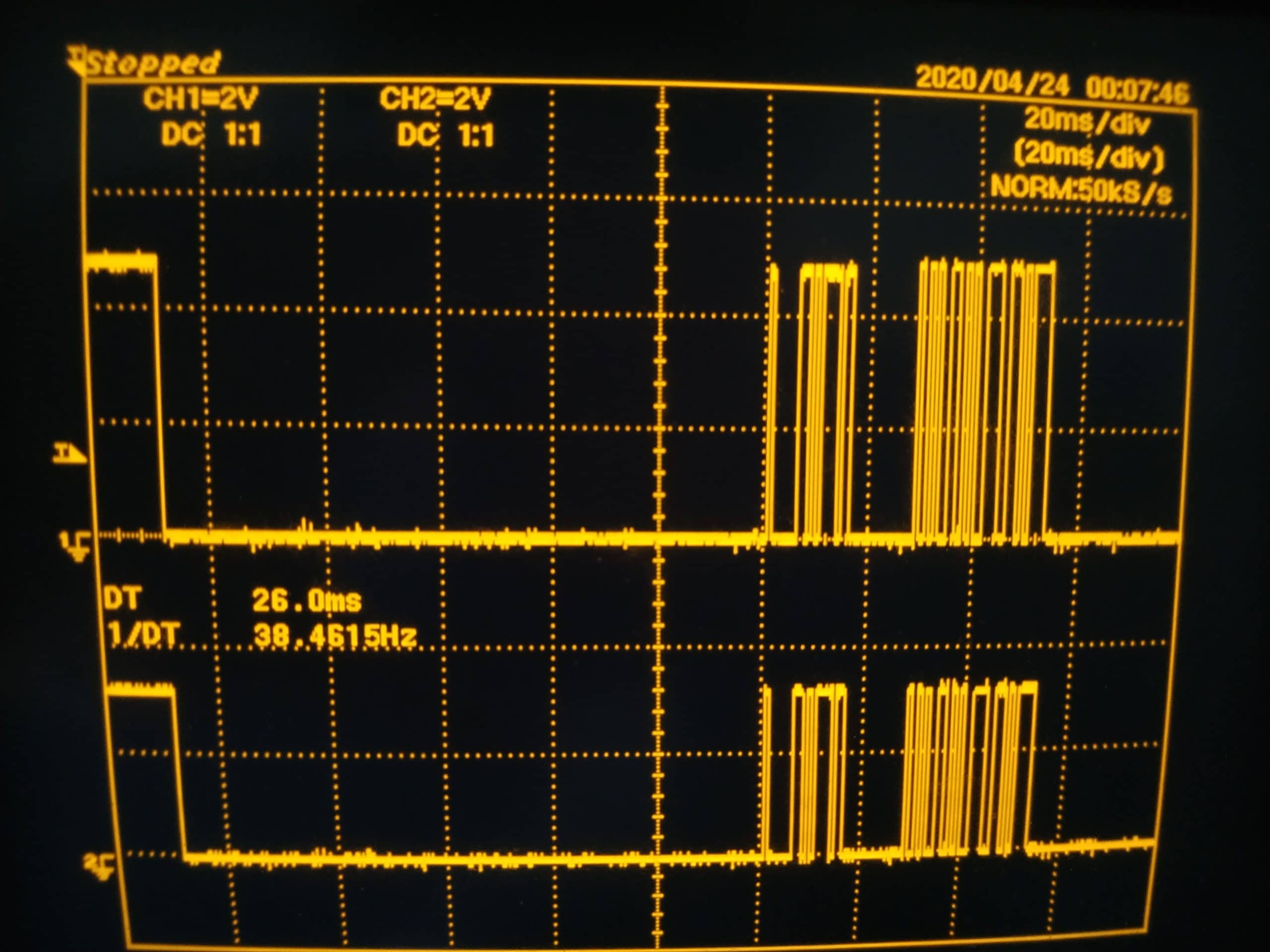
2020-07-16 at 4:14 AM #14337
I left it at the “marking” level. Here is your typical CS215 SDI-12 frame with said modification to the lib. I think this is an ADDR request (I decoded it but can’t find my notes anymore).
You can see part of the wake up frame at the beginning then the “long” 100ms wait period.
Attachments:
-
2020-07-20 at 3:54 PM #14357
Did you try adding the wait to the break before the marking? Does that work?
I modified the SDI-12 library to allow an optional extra warm-up delay, but I but the wait while the line was in break/spacing rather than in marking. I didn’t want to add the time to the marking because while sensors must be able to respond to a command within 100ms of detecting the break, they must also go back to sleep if the line is held in marking for more than that 100ms.
-
2020-07-22 at 9:38 AM #14358
That is true, I missed this in the spec. I did not try to add it while at at “break level”.
I’m guessing most (if not all) SDI-12 sensors wake up on a rising edge then start their timers from there. I think it will work all the same while respecting the SDI-12 spec.
I’ve actually got a few sensors now. As soon as I’ve got the hardware to drive them, I’ll try changing the “waiting level” to a break, see if that changes anything.
-
2020-09-01 at 5:07 AM #14548
I can confirm Sara’s idea to wait before the marking and not during seems to be more reliable, I had an issue where (rarely) the sensors did not answer to a measurement request, this seems to fixed this.
It is hard to be 100% sure about this since it doesn’t happen often but it seems to be better this way, and since it is also SDI-12 spec compliant this is certainly the way to go.
-
-
AuthorPosts
- You must be logged in to reply to this topic.