
Home › Forums › Mayfly Data Logger › 1.1 revB and Clarivue 10 Turbidity Sensor
- This topic has 1 reply, 2 voices, and was last updated 2023-03-14 at 6:56 PM by
 Shannon Hicks.
-
AuthorPosts
-
-
2023-03-14 at 12:20 PM #17685
Hello,
I have some questions on the functionality of the board with the Clarivue 10 Turbidity sensor. There have been some threads and posts that the 1.1 RevB boards can power the sensor and take readings, but when trying to use the sensor, I have been getting a reading of -9999.
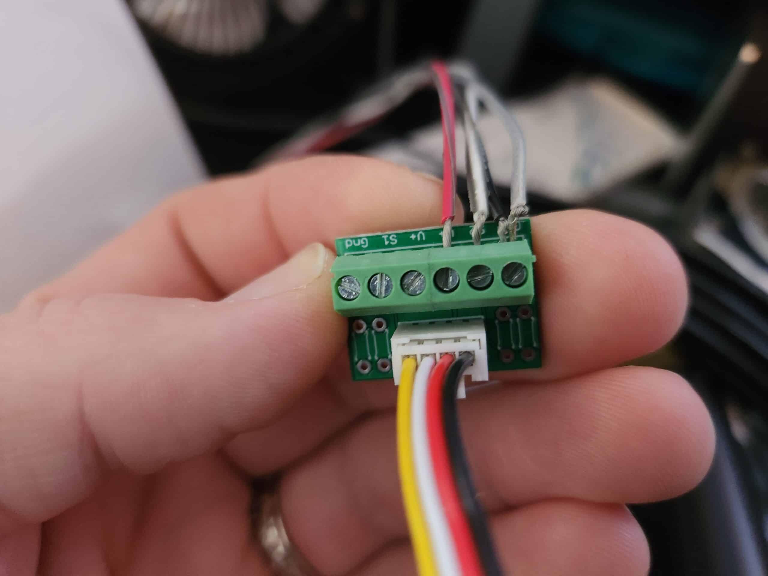
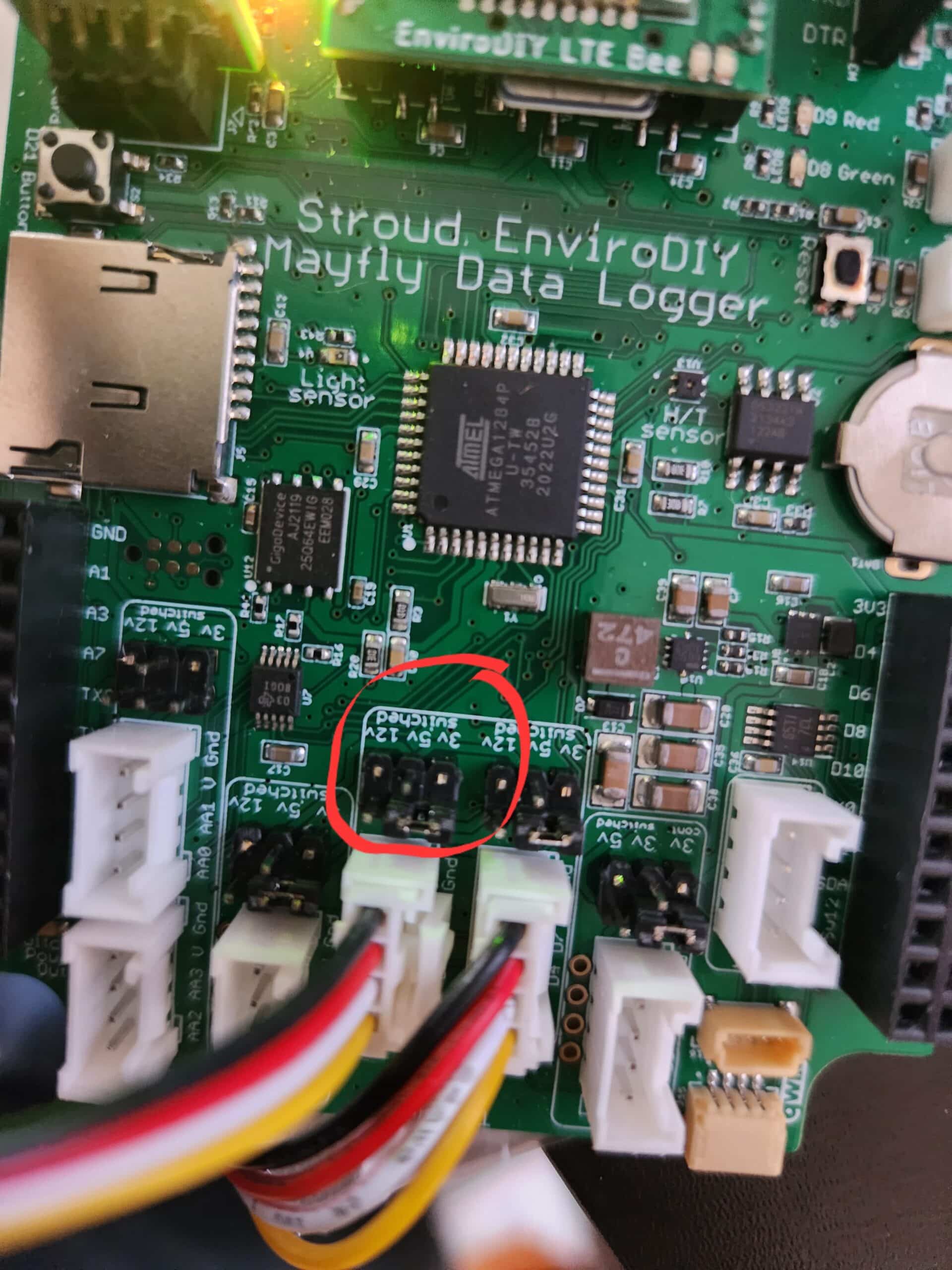
I am using the six-screw terminal block for the bare wires, and a grove jumper to D4-7. I see there are some pins by the grove jack on the board for power and was wondering the configuration for 12v power for the sensor.
Also, I wanted to ask about updated sketches for the Clarivue 10. I saw someone post code in another thread that seemed to work for them, so I have implemented that in order to get the sensor to work. These boards are the latest revision, so I’m a little lost on some of the details in features and how to configure them in hardware and software.
Any assistance is greatly appreciated! Thank you!
Pictures attached for the setup of the 6-screw terminal block and the board connections.
Attachments:
-
2023-03-14 at 6:56 PM #17689
The Mayfly makes 3.3v, 5v, or 12v, as set by the jumpers on the headers next to each Grove socket. The ClariVue sensors need 9 or 12v, but at lower temperatures (below 5C) we’ve found that some of the sensor will stop working because the Mayfly can’t produce enough current at 12v at low temperatures. So to fix this issue, you can just change the Mayfly’s 12v boost circuitry to output 9v instead, and you do this by putting a solder blob on the back of the board on solder jumper SJ25. I explained in greater detail and with a photo of the SJ25 solder blob on this post: https://www.envirodiy.org/topic/need-help-with-clarivue10-turbidity-sensors/#post-17638
Once you’ve done that, you need to set one of the SDI-12 Grove sockets to 12v (but it’ll really be 9v because your solder blob changes the 12v regulator circuit to 9v). Move one of the header jumpers from its default 3v setting to 12v. There’s an example photo of different voltage settings in the middle of this page: https://www.envirodiy.org/mayfly/hardware/jumper-settings/
Then you also need to make sure that you’re using the latest “CampbellClariVUE.h” file from Github here: https://github.com/EnviroDIY/ModularSensors/blob/master/src/sensors/CampbellClariVUE10.h because the latest version of the sensors seems to need more warmup and sample time than the ones we originally tested the library with. Specifically, lines 88 and 99 need to be changed to 8000ms and 11000ms. So either manually change those lines in the file on your computer or download the latest .h file from github and replace the one on your computer. You won’t need to make any changes to your actual logger sketch, the timing changes only need to be made in that one library file. When you compile and upload the sketch, the new sample times in the library will be used. I explained more about this issue in the other forum post as well if anyone wants to see a full description of the issue and our recommended fix.
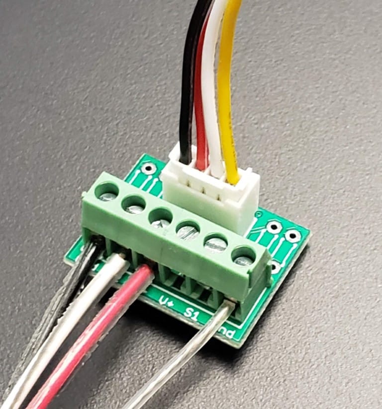
And your screw terminal board could use a little extra work to make it safer in the long run. The wire leads on the sensor cable should be cut shorter so there’s no exposed copper wire seen where the wire enters the terminal block clamp. This will prevent 2 wires from accidentally touching if they get bent or pushed around when inside the enclosure. There are 2 Ground terminals, so you can connect the black wire to one ground pin, and the clear shield wire to the other ground pin. In general, putting 2 wires into one screw terminal socket should be avoided whenever possible. The white sensor wire is data, which goes to the S2 pin of the screw terminal board, and the red sensor wires goes to either of the +V pin of the terminal board (they’re both the same). See the attached photo of an example of how we wire our ClariVUE sensors to the screw terminal board.
Attachments:
-
-
AuthorPosts
- You must be logged in to reply to this topic.