
Home › Forums › Environmental Sensors › Need Help with Clarivue10 Turbidity Sensors
Tagged: Clarivue10, CTD, Hydros21, SDI-12, sensor, temperature, turbidity
- This topic has 4 replies, 2 voices, and was last updated 2023-03-13 at 9:32 AM by
 Michael Daniel.
-
AuthorPosts
-
-
2023-02-22 at 4:15 PM #17618
Hello everyone,
I’m having a very similar problem to what James had been experiencing in this forum post. I’ve recently installed 3 Clarivue10 Turbidity sensors in stream, but only one of them (LYHWR005) works reliably. The other two (LYHWR004 and LYHWR006) typically only work for several hours a day.
I believe the problem is related to the temperature in pelican box, as the turbidity sensor at LYHWR004 typically start working by the time the Mayfly reads at least 17 degrees Celsius, and LYHWR006 works above 10 degrees Celsius. Even the reliable sensor at LYHWR005 won’t work if the Mayfly is below 0 degrees Celsius. I think the decrease in temperature is causing a short somewhere, maybe at the 4 pin connector or the 12v switch. I have a test station that lives in my office that runs perfectly well over the weekend with no light, but as soon as I keep it in a car overnight the turbidity starts going out, following the same data pattern as the other 2 in regards to temperature.
Things I’ve tried:
- Using the same code as LYHWR005
- Swapping the Mayfly
- Swapping the Turbidity Sensor
- Implementing this build flag: -D MS_SDI12_NON_CONCURRENT
- This had some success, as my test station in my office (that uses Hydros21 for CTD) would occasionally drop turbidity readings, once the build flag was utilized this stopped)
- Adding more measurements
- Reducing measurements
- Unplugging the CTD sensor
- Tightening the screws in the 4-pin to grove cable convertor
- Swapping out the Hydros21 CTD back to the Decagon10
- Trimming the wire on the Turbidity Sensor so less is exposed and none of it is tinned (based on this graphic)
I’ve also noticed more frequent readings seem to reduce this problem, lowering the maximum temperature needed to operate. This is more anecdotal, and I have yet to do any testing on it. I’m leery to increase the sampling frequency due to data costs, and I’d prefer to solve the problem another way.
Any help would be greatly appreciated. I’ve been working on this for about two months now and I still don’t have it figured out.
-
2023-02-22 at 5:30 PM #17619
What Mayfly board version are you using? The ClariVue10 seems to only work reliably with the Mayfly v1.1 RevB since it produces the most stable 12 volt output. Also, we’ve found that at room temperature the ClariVue needs about 8 seconds after the switched power is applied before it will respond to any commands, and then needs another 9 seconds to complete the actual measurement. It could be that the temperature of either the sensor or the logger is causing that interval to be longer than the code expects, causing a mis-communication between the logger and the sensor. We currently have a ClariVue10 sensor installed in a river with a Mayfly v1.1RevB, the water temperature right now is 4C and the air temp is 6C, and all data is normal.
-
2023-02-27 at 12:22 PM #17636
The Mayfly is at least v1.1, but I’m unsure what revision it is. Would it say RevB on the board somewhere?
Also, I should’ve mentioned earlier that I’ve tried to run the address change program when the turbidity sensor wasn’t working and the program couldn’t find the sensor at all, regardless of the amount of times I let it loop through the program. It just listed every address as vacant over and over again. This happened on 2 different mayfly boards with 2 different sensors. The program was able to work once it warmed up.
Would this still indicate an interval issue? Would running TestWarmUp in colder conditions allow me to see how much the interval needs to increase? Or if I changed the intervals in CampbellClariVUE10.h would I be able to test if it’s an interval issue? Would changing this interval have cascading effects that would need to be accounted for?
Or should I just get RevB boards?
-
2023-02-27 at 2:40 PM #17638
I spent the entire weekend trying to recreate the SDI-12 communication issue with the ClariVue sensors by placing a bunch of Mayfly loggers and turbidity sensors in my freezer and refrigerator in various combinations. I was able to isolate the problem to the Mayfly v1.1 boards not being able to produce sufficient instantaneous current at 12 volts when the ClariVue is first powered up when Mayfly board temperatures are below approximately 5 degrees C. The exact temperature depended slightly on the individual Mayfly board, but more important was the version of the ClariVue sensor. We have some that were made last year and some the were made about a month ago, and I found that the power requirements and timing of the SDI-12 commands were slightly different between the two.
Even at room temperature, I found that some of the measurement commands to the sensor weren’t always successful with the warmup and measurement times as originally defined in the CampbellClariVUE10.h file (5.5 seconds and 9.5 seconds, respectively). Changing them to 8 seconds and 11 seconds resulted in 100% success rate at room temperatures (and all the way down to -20C with the sensor powered by an external source). I just updated the .h file on Github, but you can simply edit your existing file with a basic text editor (not Word) to change the warmup time in line 88 from 5500 to 8000 (remember that Arduino code uses milliseconds to denote time intervals), and change the measurement time in line 99 from 9500 to 11000.
But to address the sensor power issue, we will be revising the 5-volt and 12-volt circuitry on future Mayfly board versions to switch back to the original design that worked in prototype testing a few years ago but couldn’t be implemented into full production because of semiconductor shortage problems at that time. We’ve still got a bunch of those prototypes deployed and powering high-current 12-volt sensors with no problems, it was just unfortunate that we weren’t able to use those parts in the board production because they were impossible to buy for the past 2 years.
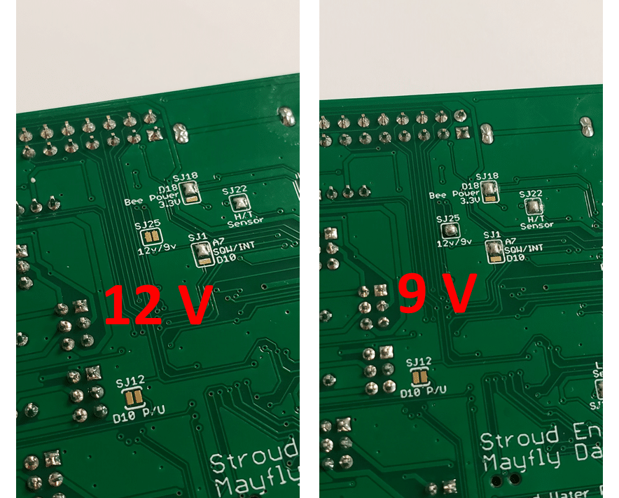
In the meantime, you can easily modify your Mayfly v1.1 boards to generate 9 volts instead of 12 volts, and I tested all of our ClariVue sensors and various Mayfly v1.1 boards using this 9-volt setting and had no trouble powering and communicating with the sensor from -20C to +30C. On the back of the Mayfly board, there’s a solder jumper labeled SJ25 that says “12v/9v”. It’s default position as shipped from us is open, meaning you’ll see two little separate gold pads. You just have to bridge those two pads together with a tiny blob of solder to configure the board’s circuitry to generate 9V instead of 12V. So on the front of the Mayfly board, with the pin jumper next to a SDI-12 Grove jack set to the 12V, you’ll actually get 9V there, and your ClariVue sensor should still work fine and continue to communicate with the Mayfly even if the Mayfly air temp goes way below freezing. I’ve included a photo showing what the back of the Mayfly board should look like once you’ve put a solder blob on the SJ25 pads to enable the 9-volt setting.
Attachments:
-
2023-03-13 at 9:32 AM #17679
Thank you so much for all your help and hard work! Everything is working perfectly now.
-
-
AuthorPosts
- You must be logged in to reply to this topic.