
Home › Forums › Other Data Loggers › Using the Teensy 3.5
- This topic has 12 replies, 2 voices, and was last updated 2023-10-27 at 3:54 PM by
Rick Vogel.
-
AuthorPosts
-
-
2021-08-03 at 1:07 PM #15779
Setting up this topic at the request of @neilh to discuss advances we have made using the Teensy 3.5 board for logging data and have been able to establish remote updating, as well as, a bootloader that allows for boot from the loaded program, but checks for boot file on the uSD card first as a potential update to the program.
Bootloader is taken from the uTasker project: https://www.utasker.com/kinetis/TEENSY_3.5.html
Solar Charger(Dual Battery version): https://cdn.shopify.com/s/files/1/0079/6003/5417/files/ASC30W_Installation_Manual.pdf
Cellular: XBee LTE-M/NB IoT
- Used for both MQTT with TLS 1.2 and FTP-Secure for remote updating of Xbee and Teensy files
- Teensy files are pulled down by Xbee and transferred via serial to Teensy. Teensy writes to SD Card as received and reboots
- Used for both MQTT with TLS 1.2 and FTP-Secure for remote updating of Xbee and Teensy files
-
2021-08-03 at 2:57 PM #15783
@vogelrnws thanks. Would you have an overall schematic of it. Sounds like Solar to +12V. Then guessing +12V battery that is the main power source. Then Teensy3.5 supply 3.5to5.5V, possibly also Xbee LTE boards
https://www.pjrc.com/store/teensy35.html
Probably a carrier board for the Teensy3.4 and LTE board?
-
2021-08-03 at 3:09 PM #15785
@neilh,
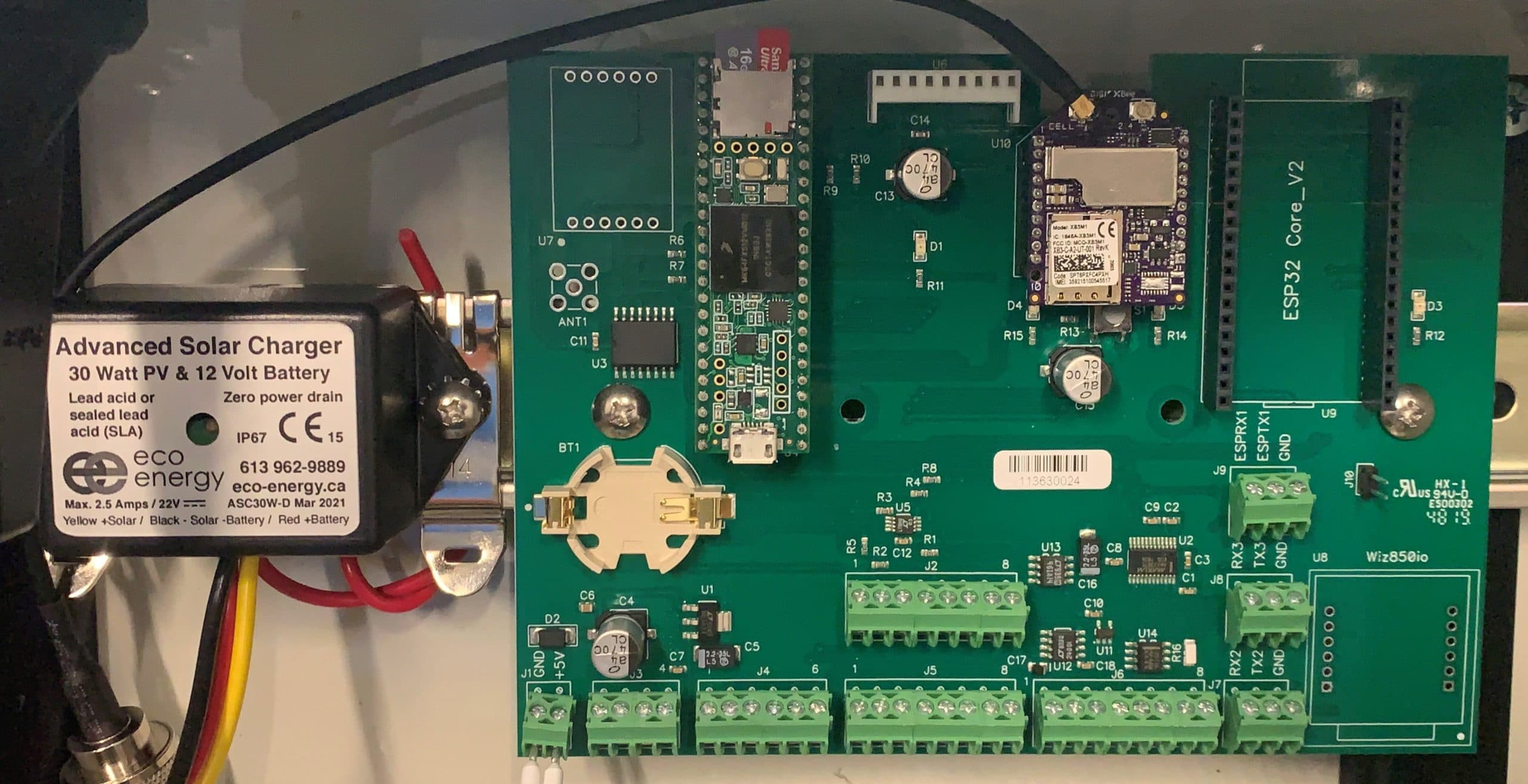
Yes, we have solar to the charger and into (2)12V 9aH batteries (in parallel). The Teensy and Xbee are on a custom motherboard we designed. Has lots of the IO broken out and spots for Adafruit GPS, RTC battery, ESP32 (older requirement) and Wiz850io Ethernet.
See pic attached
Attachments:
-
2021-08-03 at 3:16 PM #15787
12V to 5V is a DC/DC Din Rail supply P/N: MDR-20-5. The board takes in 5V and and has a 3.3V LDO onboard for those 3.3V parts that pull more than the teensy 3.3V output can provide.
-
2021-08-03 at 5:02 PM #15789
Ahh very nice. I’m sure its worth it to get a standard design for all climates, and able to cope with keeping some sensors warm. Seems like the cost is going to go up dramatically though. Powering is a lot of cost and of course IP65 space is costly (for those batteries!!). I wonder if it is open sourced, or a private contract design. I use a 4.4AH LiIon, which is quite large for the Mayfly, and of course it can only charge at a max of 0.5A/hr – which means the solar panel is only about 3Watts (though easy to oversize to cope with shading) . Thanks for sharing and the references.
-
2021-08-03 at 6:08 PM #15790
We use a polycase 12x10x6 customized enclosure for under $85 with everything predrilled https://www.polycase.com/yh-121006.
We made a custom din rail bracket to hold the two batteries. 10W panel for solar but charger will accommodate up to 30W
-
2021-08-03 at 7:03 PM #15791
Thanks, good for reference – the critical aspect of any plastic outdoor box is I understand polycarbonate and those IP65 seals 🙂 Keep out the falling rain. Those ants like to get in if they can, so it is a challenge. I really appreciate the detailed guide of what to think about with https://www.envirodiy.org/mayfly-sensor-station-manual/ though I choose my polycarbonate box based on the project.
When building a system, I do try and document it for myself so that I can easily repeat it, and also share it. The Mayfly can fit in a small space ~ NBB-15240 with the uSD facing outwards for easy offloading.
Sometimes though its the instrument wires and dessicant that need routing space, so I’ve also been using the Bud PTQ-11050 and for testing PTQ-11050-C.Still it would be soo nice to have a processor with at least 4 UARTs, an embedded USB host, and a 1M flash, enough ram and timers for totalizing/counting … with a little screen for site provisioning. I’m playing around with the Wio Terminal – https://wiki.seeedstudio.com/Wio-Terminal-Getting-Started/ but how to get the sleep power usage down, and have it take an Xbee format socket with Digi LTE powering, with all the software open source license…. as ever a variety of engineering challenges. 🙂
-
2021-08-04 at 1:15 PM #15794
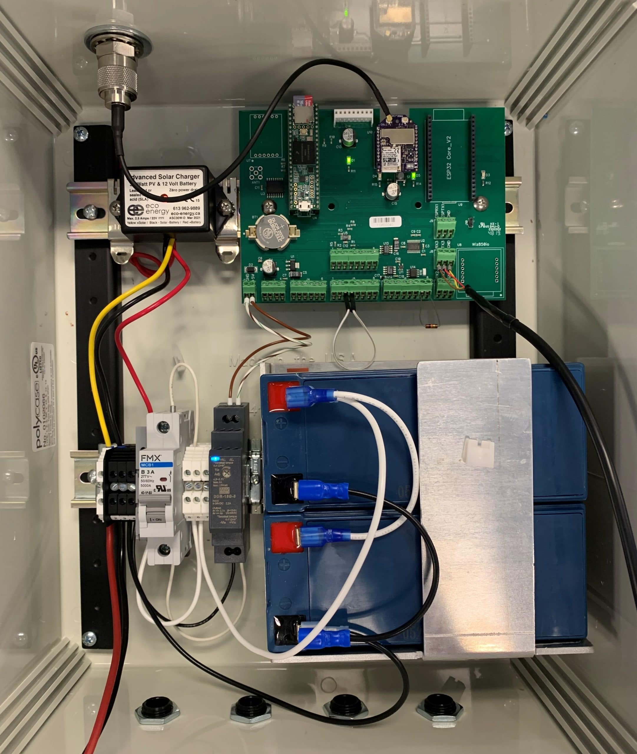
I misspoke on the DC/DC supply. It is a Meanwell DDR-15G-5. Pic of the guts on that polycase is attached.
Attachments:
-
2021-08-05 at 10:07 PM #15813
@vogelrnws nice to se the layout. That battery holder looks pretty solid and as you said 2 *12V * 9Ah gives 216WHr of capacity. a LiIon at 4.4AH @ 4V is 16Ah.
Its great to have a discussion about the mechanical side, what works, what doesn’t work so well.
Seems like on of the challenges is that uSD is right up against the side of the cabinet – doesn’t appear like it can be easily removed. Would require the Teensy 3.5 to be pulled first.
I wonder also if there is any protection for static/lightening on the instrument leads. That’s a problem in certain parts of the country.The DIN rails take some thinking about. The issue as I see it is how to do assembly simple and reliably. If the screws are inserted from the front, and require a nut at the back to hold it, it can become a challenge for replacement in the field.
https://www.mcmaster.com/din-rails/ shows some of the options for clips that might solve that.
For the Mayfly, in the Arduino style of a low cost environment, I’ve been using a plastic polycarbonate bar, and configuring it for the mayfly holes. Here is a write up .. Bud Ptq 11050 Enclosure
-
2023-10-26 at 9:01 PM #18141
@vogelrnws I wonder how its going. I see that Teensy is moving to a Teensy4.0 CortexM7
-
2023-10-27 at 7:00 AM #18142
@neilh20 Yes, the chip supply pretty much put a spike in the Teensy 3.5 for any type of continued development and usage with that chipset. We used the 3.5 because of it’s 5V tolerant I/O. The Teensy 4.1 did not have that so the project stalled for a bit. I believe the folks who have taken that project over are considering moving the XBee to a Campbell Scientific datalogger.
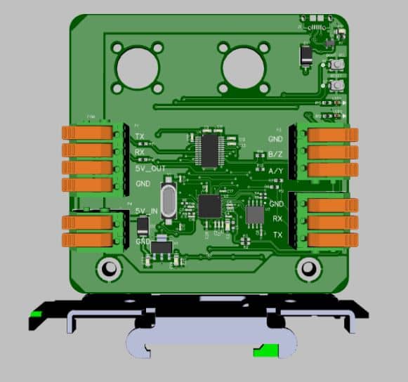
Outside of that project I started building boards using the RP2040 microcontroller used in the RPi PICO. It’s very versatile, the drag and drop bootloader is a very nice feature and its still very much usable within the Arduino framework. Picture attached is a version used in one of our systems that mounts to a din rail and has the mounting holes built in for our fiber optic modem. RS-485/RS-232 on one side. Power and dedicated RS232 and power for the fiber modem on the left. Board communications with user for debug/loading are via usb although the part itself is missing in this picture (top right)
Attachments:
-
2023-10-27 at 3:44 PM #18150
Wow nice to see the pictures and mechanical detail. I always find that a challenge to get integrated early – mostly because I’m doing everthing. Is it part of an open source project? sounds like its for a specific translator/extender fiber optics to copper RS485/RS23 In looking over the Rpi PICO, while an amazing processor with program stored in a serial flash device, seemed like there wasn’t a lot of serial peripherals only 2 UARTs . At least for me that was show stopper.
I’ve just posted on a project I’ve been chipping away at https://www.envirodiy.org/topic/using-samd51-wio-terminal/ and it has the USB drivers for the drag and drop bootloader programming with the .uf2 file :), which hopefully can also be good for remote OTP (over the air programming)
-
2023-10-27 at 3:54 PM #18151
Yes, this was a custom board I designed for the NWS ASOS program. We are using it for a translator to connect a Vaisala HMP-155E to the ASOS. The original ASOS is RS-232 over fiber and we aren’t able to change the source code any longer. So adding a new sensor required me to make the HMP-155E talk to our system like it was a different sensor. Taking in the RS-485 data stream from the sensor and reformatting that data to report as an older TSL 1088 unit.
The Rpi Pico only has 2 uarts but it also has serialPIO ports than can be configured to run many different peripherals
-
-
AuthorPosts
- You must be logged in to reply to this topic.