
Home › Forums › Environmental Sensors › Inexpensive DIY conductivity sensor
- This topic has 19 replies, 5 voices, and was last updated 2020-12-14 at 9:31 PM by
 neilh20.
-
AuthorPosts
-
-
2020-01-08 at 11:19 AM #13549
Hi All
Ive put together a very basic conductivity probe that provides an indication(unit-less) of the presence of water.
On the probe end Im using gold plated terminals for their corrosion resistance properties and an insane amount of “marine grade” heat shrink.
Sending 5v to one terminal and measuring any voltage received from the other terminal before sending it to ground.
Having an exact measurement is not necessary, just need to have clear indication when the terminals are submerged in water.My concerns are corrosion and how materials that may also be present, soil, sand etc, will
impact the readings. Lots of cal work is in order.
Any thoughts would be greatly appreciated.My hopes are that this cheap “sensor” works for extended periods of time in the field. But if not, I have been eye-balling an inexpensive fluid sensing optical IR sensor that seems to work well.
Thanks a lot everyone
EvanAttachments:
-
2020-01-08 at 2:07 PM #13555
Hi Charles,
I’ve used titanium rod – 1/16″ Dia 6″ length= $1.62 – https://www.mcmaster.com/89145k28
and its easy to crimp a wire to the rod. I might be able to find a picture of it at some point.
Its also possible to drill two holes through a PVC end cap, and then snuggly push the rod through with a watersealant adhesive on it – uses the friction fit of the rod, with the watersealant adhesive as secondary water tight guarantee. That then provides small chamber to protect electrical connections. I used a crimp connections, with solder as a glue, are better for long term survivability.
I haven’t had a lot of field experience with the titanium example though.One area to look for in ideas of detection is the analog front end of “water leak detectors/alarms” and plant water probes and rain detectors
http://www.hobby-circuits.com/circuits/sensor/fluid-and-humidityPart of the issue is that pure water doesn’t conduct. Its the salts/ions that conduct electrons.
So what type of ionic conduction is likely in your water – and more to the point if you have too much current – possibly like in your proposed simple detector – will all the ionic transport be used up. If its flowing water probably not. Rain detectors use a large surface area to catch water and then have a high impedance detection circuit.
These have some good descriptions:
http://www.hobby-circuits.com/circuits/sensor/fluid-and-humidity/783/plant-watering-watcher-circuit-schematic
http://www.hobby-circuits.com/circuits/sensor/fluid-and-humidity/263/plants-watering-watcherI’m also looking at a water disconnect sensor for stream reaches here in the Western USA. With the long hot summers, the biology of stream pools starts to change when the stream flow reaches zero. Detecting no flow or low flow in a real stream reach is challenging. Perhaps measuring a stream disconnect might be easier and help with stream management. So I’m interested in what your experience is.
-
2020-01-08 at 3:58 PM #13558
Hi neilh
Thanks a lot for your response.
Good idea with the titanium rod. How would you cut that?
Right now, I plan to use PVC to anchor the array to streambeds. I haven’t put the first one together yet, but I intend to use a coupler and end cap that will accommodate a cable gland big enough for my 5-conductor, 18awg cable. The housing for the sensors has been the most challenging part of the build so far. Ultimately I hope to make it as small as possible, but right now, it’s quite hefty.I intend to validate its precision with gradient testing, where the salt concentration is increased in each sample, the value measured, and recorded.
I want to produce an inexpensive probe that is sensitive enough to consistently detect varying conductance ranges, both in the lab and field.If I cant make something that is robust and consistent between measurements, Ill probably use one of these:
https://www.adafruit.com/product/3397
It does add some cost to the unit, but its small size and sensitivity make it an attractive avenue for me.I’ve also thought about throwing a handful of DS18B20s onto a bus together and using the measured delta in temperature to determine water depth.
– -
2020-01-09 at 3:17 PM #13583
Cutting the rod in small diameter wasn’t a problem for me. Ideally it should be a square cut.
Ti oxidation layer protects it https://cdn.ymaws.com/titanium.org/resource/resmgr/2010_2014_papers/HouserRobert_2011.pdfYou may have two different sensors if you want to be able to do “water detection” v “conductance”
Also depends on power consideration, and how long it should be left between maintenance visits.
Conductance – ionic transport in water – is much studied and seems to get tricky pretty fast, but maybe it doesn’t have to be that accurate.
Stream water gets a lot of particles in it as flow is reduced.
http://reefkeeping.com/issues/2004-04/rhf/feature/index.phpImplementing a Low Cost, Battery Powered, TDS Meter Using MCU and PSoC
Mechanical considerations is always a challenge. If you are looking at an array of sensors, – I wonder what distance between them. If they are going to be linearly distributed, then perhaps a PVC (1″? 3/4″) pipe could be a mechanical holder and wire conduit. Electrodes could be inserted in joining sections. That would make it accurate for intra-electrode spacing. There could be some challenges assembly two titanium electrodes with wires, inside a 1″ PVC pipe joiner, but seems doable.
The array of temperature sensors also is something I’ve been thinking of. I like thermistors for their low thermal inertia – however both need to be sealed from direct water contact, and that needs to be both thermally conductive and prevent long term water migration.
Thermistor v DS18B20 is partly how many units are likely to be produced. The DS18B20 require the individual ID numbers to be characterized in the array, thermistors require an analog multiplexing scheme. Both are dependent on how far from a datalogger. -
2020-01-09 at 3:24 PM #13585
-
2020-01-10 at 12:52 PM #13593
Wow, thanks a lot for the literature, and also for the new resources. Public Lab seems to have some really good stuff and I will for sure be lurking around there.
I see that DC voltage is not recommended for use in conductivity measurements for electrochemical reasons, as well as 5v is high and is not required for successful conductivity measurements.
With this, I see that using AC voltage, sine waves, is the practice. I have found a few things online about duping sine waves with microcontrollers, but nothing that seems to be solid. Have you had any practice with this? Can the Mayfly be used to produce low-voltage alternating current?
If so, what other mechanisms are needed? Look-up tables?
I am quickly reaching the ceiling on my know-how. Can this be done?Initially my aim was to produce an inexpensive, yet robust, logger that will spend significant amounts of time deployed and could detect and record the presence of water. But it would seem that I am working towards measuring TDS, which I am very much okay with. If at the end of this project I can’t seem to make a reliable, and deployable TDS sensor, I would have at least made a device that can determine the presence of water.
The majority of the time, these sensors will not be exposed to water and will spend most of their time loitering in dry stream beds, at least that’s what we think.I was pleased to see that temperature is a critical metric when determining TDS. I initially planned to use temperature sensors to determine the presence of water, so Ive got a few on hand. Lastly, my current probe consist of one DS18B20 with the electrodes straddling it. The temp sensors are cheap Asian market style, 5 for $10 sorta thing. They seem to work well and follow the oneWire library set.
I am assuming the metal casing around the senor is stainless, is it possible that the temp housing could be providing ions the electrodes.For the probe housing, I am currently using 1.5″ PVC parts. That decision was solely driven by the size of the cable and the pass-thru gland needed to achieve a water-tight seal from the enclosure. I was worried about voltage drop, so I sized way up to 18awg, from the 22(?) of the off-the-shelf jumpers/sensors parts.
-
2020-01-10 at 6:06 PM #13595
The mayfly can generate a square wave which can then be filtered/rounded to a sinish wave. It would still need to be amplified with a low current op-amp
For TDS trials I personally would start with something like this, though might need more research – it has methods of calibration. The qu is just what sort of value does the results give
https://www.dfrobot.com/product-1797.html
https://github.com/DFRobot/DFRobot_EC – I haven’t found a diagram yet
The cable, for outdoors (no radio emf) doesn’t need to be the shielded cable.
My guess Titanium sensors of similar size would work instead of the defined lab sensor. -
2020-01-14 at 11:09 AM #13609
Because my original goal is not to measure conductivity, but presence only, I am hesitant to buy an off-the-shelf variant, and I think that it would be awesome to make my instrument.
Right now, precision is more important to me than accuracy. Though, if it seems possible and I can consistently obtain realistic values, that may change.
You’ve given me a lot to chew on, and I will for sure be reaching back out about this. My electrical know-how threshold has been met with Wien Bridges and low power op amps.
The cable I’ve got isn’t shielded, but is essentially power tool cable and is rated within the SOOW category. I think my only concern with it at the moment is how tasty the local fauna will find it when they’re deployed.
-
2020-01-14 at 3:40 PM #13613
Its a good discussion, and I’m interested in the context of the study of intermittent streams.
There are a lot of examples of detecting “water leaks”, that is the physical situation of going from no water, to “tap water” – a relatively low TDS water.
For an intermittent stream, I imagine its going from a physical water present (with potentially high TDS) to a water drying up condition. That is the sensors are likely to have the full “benefit” of living water, algae – and then gradual drying up.Where it gets placed in the stream channel and how “wires” are run out is part of the setup. I would think a sacrificial outer cord, flexible PVC tubing, would be basic starting point. Some critters won’t like the woven metal outer shields of some cables.
For low power I would think that would also support a periodic check – ie a test every 15minutes. That may help with the powering scenario.
Working with indoor tap “water leak” detection I bought a water alarm with a “4ft rope connector” Honeywell RCHWES4/U RCHWES4 Wi-Fi Water Leak Detector Rope Sensor https://www.amazon.com/gp/product/B01J7EVB1G/ref=ppx_yo_dt_b_asin_title_o07_s01?ie=UTF8&psc=1
I haven’t experimented with the way that it works yet :). I just did the basic test of wet parts of it and see the alarm go off, before I installed it under the floorboards, directly beneath a bath where I had some water leak in the past.So it may take a few small steps to find out what works best in the field.
-
2020-03-10 at 10:15 PM #13915
Hi Evan, I was wondering how your experiments are going.
I was thinking of constructing a ModularSensors class along what you had been talking about.
So this follows the
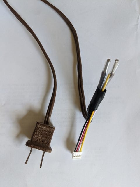
https://hackaday.io/project/7008-fly-wars-a-hackers-solution-to-world-hunger/log/24646-three-dollar-ec-ppm-meter-arduino
with a series voltage switched R of about 500, and an IEC plug
The class could be
AnalogEC sensorEC(PowerPin, AnalogPin, EC_resistor, WaterTemperature_C);
Neil -
2020-03-12 at 7:55 AM #13917
Hi Neil!
Once I realized that I wanted more information than just the presence of water alone, and that reasonable measurements are possible for cheap, I placed the EC sensor on the back burner, for now. At least until my head is above water.
I do intend on coming back to this, pending demand. Right now, I am having a lot of fun with an optical IR sensor.Though, if you did make the class, I believe I would use it. Lucky for Sara, I had waited to send that email asking about how homemade sensor data made its way to MMW.
I am still figuring what will be the best strategy, EC may be it and may come back to this sooner than I expect.I will for sure be reaching out.
-Evan
-
2020-05-17 at 9:06 AM #14165
I had seen that post on the $3 EC meter several months ago and experimented with building a variation of that sensor but had little success. Thought that it might be better to buy something that already works, to better understand it, and not try to reinvent the wheel.
I would love to see what you come up with for a ModularSensors class. I might give it another try.
Robert
-
-
2020-05-15 at 2:12 PM #14164
Hi…i could say about the functionality of the sensor which can help you to choose the one rather than looking for inexpensive sensors. The current through the liquid will be that voltage divided by the effective total liquid resistance through the hole and back around the outside of the pair of cores. The cylinder inside the cores will dominate this resistance since its length to width ratio is larger than the effective length to width ratio of the rest of the current path. When buying the one check the conductivity by keeping in mind about the flow.
-
2020-05-17 at 1:32 PM #14167
Hi Robert, I really like your Continuous Logger Post and the installation detail.
I’d be happy to share what I’m doing, and I’ve just finishing up a ModularSensors class last week.
just thought I had posted here, and it hasn’t shown up, so trying again – here are the core details
https://github.com/neilh10/ModularSensors/blob/rel1_dvlp1m/src/sensors/analogElecConductivity.h
https://github.com/neilh10/ModularSensors/blob/rel1_dvlp1m/src/sensors/analogElecConductivity.cpp
Comments and code review welcome.
Its using an analog port, per the original post, and powered by a toggling port bit.
The actual target is a “Relative EC” as a “Stream Disconnect Sensor”
https://agupubs.onlinelibrary.wiley.com/doi/pdf/10.1002/2013WR015158
so I’m not paying attention to the units of measurement, though still calculating them as uS/cm2
Attachments:
-
2020-05-18 at 5:33 PM #14171
@movingplaid for the basic EC sensor above, and 10bit ADC and running at 2minutes sampling – which is way too fast for a simple DC switched EC sensor got a pretty good result. Graph below.
Next stage is to run it overnight, and for simplicity will graph it on MMW
Attachments:
-
2020-08-18 at 8:58 PM #14494
Hi Neil,
How did your experiment go? Have you managed any field deployments?
I’m looking at options for developing a DIY conductivity sensor, to go along with DIY turbidity and depth/pressure. Ideally it would be calibrated, but relative conductivity might be okay.
James
-
2020-08-18 at 9:57 PM #14495
Hi James, great to hear someone else interested. I just got a “relative EC” working nicely and gave them out to be deployed last week.
The “relative EC” is to be able to measure stream disconnect. For the <<dry>> hot climate we have in California, looking to monitor when the stream goes dry.
There is no reason why it can’t calibrated. Need to pay attention to a few specific components, and of course determine what accuracy you want, and can get.
I’m in process of putting a package together as Open Source Hardware.
I’ve developed a board and MS sensor software that interfaces on the Mayfly Analog port using the internal ADC, (tested), for the “relative EC”.It optionally, (not tested), can be built to be plugged into Seeed connector with the more accurate ADS1115.
So the unit spec iw to be standalone, with 40′ of cable, and bootnet access(walk up remove microSD) and looks like this
https://github.com/neilh10/ms_hardware/blob/master/ec_analog/Ec%20Asm%20with%20sensor%20cable%20(Large).jpg
and the internals running with an standalone 3.6Vbattery
https://github.com/neilh10/ms_hardware/blob/master/ec_analog/Ex%20Asm%20Top%20(Large).jpgWhat is the Turbidity and Depth sensor you are looking to use ?
How are you looking to access the data?
How comfortable are you reading circuits and building a PCB from a BOM? -
2020-08-18 at 10:56 PM #14496
Hi Neil,
We are looking at developing a network of Mayfly stations for characterizing a catchment, with three tiers of sensor quality. The top tier (~10% of stations) would have top-standard sensors, and would be used to calculate loads at the bottom of the catchment, or investigate interesting signatures at certain sites. The middle tier (30%) will use cheaper, but reliable sensors, e.g. Decagon CTD, Yosemitech Turbidity etc. The bottom rung (60%) will be DIY quality, i.e. cheap but reliable, and is aimed at increasing resolution throughout the catchment. This work would fall into the latter.
We were thinking about using washing machine turbidity sensors for the DIY tier, but these don’t seem to be reliable for field applications (based on our lab experiments). I have had some success building my own turbidity sensor using a piece of PVC pipe, a smaller acrylic pipe with a red LED, 180 and 90 degree LDRs. This worked really well in the lab, but seems to pick up daylight in the field. I found an interesting paper (https://ieeexplore.ieee.org/document/8337739/) that uses the same design, but with photo diodes and an infrared LED light source. They were planning to deploy in the field, but I imagine they will come across the same problem. I think there is potential down this pathway, but haven’t found an ideal solution yet.
I would like to add a DIY conductivity sensor to go along with the DIY turbidity sensor, and possibly other DIY sensors (e.g. depth, UV absorbance etc). The overall aim is to build relationships with contaminants (e.g. TN, NNN, DRP, TP, ECOLI, TSS..) over storm events, and better understand spatial and temporal load contributions to sensitive receiving environments.
Ideally we would telemeter data to MMW, but we are having a few issues with the XBee LTE. It’s not a complete disaster is we have to manually download the Mayfly, but better for community communication if it’s live on the web.
This work is through the University of Waikato in New Zealand, so there are some very experienced technicians who can help with the build. We also have a 3D printer, which may make things easier.
I am just beginning this journey so I will probably ask a few silly questions along the way 🙂
James
-
2020-08-19 at 12:47 AM #14497
Hey happy to contribute where I can.
My wife and I started a trip in Hamilton with some friends in 1990. Spent 2 months traveling round NZ as part of a round the world trip. 🙂I have a fork of ModularSensors and focus on a small subset of sensors, scaleability through ability to build releases, download a defined binary of the code, and test specific configurations
https://github.com/neilh10/ModularSensors/wiki
As and when there is a request, if its useful, I’m happy to migrate from my fork back into core software. Personally I’m following the traditional path of a multistream development, git supports so well, and where its a good place to stabilize releases.I’ve got a release of new features with reliable delivery to MMW that is working well with Xbee LTE.
IHMO, I’ve always found there is work in defining a sensor configuration, testing it and then managing the stability of it through defined releases.
Be happy to chat more. -
2020-12-14 at 9:31 PM #14921
The latest release of ModularSensors 0.27.0 has a new simple electrical conductivity sensors ~ AnalogElecConductivity.h/.cpp
Thanks to Sara for accepting it as a MS sensor and formatting it to the latest documentation style. See the amazing Doxygen generated https://envirodiy.github.io/ModularSensors/group__sensor__analog__cond.html
Sara has also added to example/menu_a_la_carte.ino
See Variable* analogEc_condIts a “simple sensor” ~ meaning low cost low resolution using the Mayfly mega1284’s ADC 10bit.I should emphasize as released, all calibration and determination of fitness for purpose. safety analysis for specific usage, is on the user.Its based on a standalone Mayfly sensor I built for monitoring “Stream Disconnect”.The purpose is to measure when a stream’s level hydrograph is dropping, and to be able to determine approximately when the stream’s flows “disconnect”. In recent studies for streams in the dry Mediterranean Western USA this is a significant event for the streams biology.I hope to do a separate discussion on the full unit I built, including a separate interface board but that will have to be for later. The wip is at https://github.com/neilh10/ModularSensors/wiki/Stream-Disconnect-EC-Monitor
-
-
AuthorPosts


- You must be logged in to reply to this topic.