
Home › Forums › Mayfly Data Logger › How to get a 5V signal out based on a sensor reading
Tagged: data logger, mayfly
- This topic has 6 replies, 3 voices, and was last updated 2021-06-22 at 7:25 AM by
Charitha (CJ).
-
AuthorPosts
-
-
2021-06-09 at 6:22 PM #15604
I’m using a mayfly logger and trying to send out a 0-5V signal out to an actuator to be controlled using data collected thorough a CTD sensor (Hydros 21). I have used the ‘DRWI_NoCellular.ino’ sketch referred in the monitoring station manual and was able to get the data logger to collect and store the data. I’ve been trying to figure out how to send out a signal. I read in some other forum answers that by setting D22 high/low I can change the voltage of the SW5 SW3 and grove terminals all together. However, the CTD sensor is connected to D6-7 (grove terminal) and being controlled by D22 in the sketch. Is there a way to do this? Maybe isolate the above terminals or something.
Basically I’m trying to look at the water level reading from the CTD and based on a logical condition, send out a 0 or 5V signal out.
This is my first arduino project. Any help is much appreciated. Thank you.
-
2021-06-10 at 12:27 PM #15605
Check out this repo: https://github.com/EnviroDIY/Trigger
This example sketch shows how it would be used in combination with the ModularSensors library: https://github.com/EnviroDIY/Trigger/blob/master/examples/simple_logging/simple_logging.ino
It’s old, so some components are probably outdated, but it’s generally what you’re looking for.
-
2021-06-10 at 10:52 PM #15608
What’s the duration of the 5v signal you want to generate? And how much current does the 5v actuator draw? Pin D22 controls the switched 3.3v and 5v outputs together, so there’s no way to separate the two. However, a Hydros-21 CTD sensor uses very little current when it’s constantly powered, so you could plug the CTD into the D4-5 Grove jack, then move the jumper switch for the D4-5 jack over to the “3.3v” setting instead of the “3.3v Switched” setting, so the sensor would be constantly powered. Be sure to change the CTD channel number in your sketch to “5” instead of “7”. Your CTD sensor will now be constantly powered, but will only use measureable amounts of power when you send the SDI-12 command to take a reading, which most sketched do once every 5 minutes. Then you could put the jumper on the D10-11 jack set to “5v switched” and when you turn on D22, the Grove jack’s Vcc pin will get 5 volts. This would only work if you have no other sensors on the D22 line that you want to control.
The other option would be to use a Grove relay board, like one of the ones from here: https://wiki.seeedstudio.com/Seeed_Relay_Page/ (only the ones with 3v excitation though) which would allow you to control a relay that’s capable of switching high current or high voltage signals. But you’d still have to figure out where you’re getting the 5v signal, which again depends on how much current you’re trying to control and for how long.
-
2021-06-11 at 2:22 PM #15611
Thank you so much for the replies. The 5V signal duration varies with site and rain event conditions. However, with my previous field work, using a campbell system, the valve controlled by the actuator was open (5V) for an average of 10 mins (but could be a few hours on extreme rainfall events). How would the duration affect the mayfly? I’m using 12V (15AH) batteries to power the system. The actuator has separate power and signal inputs and the signal draws a very low current (I’m not quite sure how much however, the campbell loggers were able to provide it safely). I must note that the actuator actually requires a 0-10V signal and I’m thinking of using a PWM to voltage convertor (http://www.icstation.com/voltage-converter-module-adjustable-converter-power-module-digital-analog-signal-p-12498.html). Therefore, the signal from the mayfly will be directed in to the convertor, which has its own power supply to generate the 0-10V signal (if I understand it correctly).
I hope I’m making sense. My knowledge is quite limited when it comes to electrical engineering.
-
2021-06-17 at 2:03 PM #15619
I changed the connections as you have suggested. I noticed that D22 gets activated when .logData() function is run. And because the data reading interval is controlled through .logData() I can’t seem to do much. When the CTD is connected to the D4-5 jack, do I still have to have SDI12Power set to 22 in the code below and is this what causes the above issue?
DecagonCTD ctd(*CTDSDI12address, SDI12Power, SDI12Data, CTDNumberReadings);
Do i have to edit LoggerBase files to have a longer 5V output?
-
-
2021-06-17 at 2:19 PM #15620
I’d have to see the rest of your sketch to know what you’re trying to accomplish with the 5v output. If you put the CTD sensor on the D4-5 jack, and move the jumper to constant 3.3v, then the SDI12 power pin part of the code doesn’t really matter, but that kind of stuff gets declared early in sketch, usually in the setup function. The bigger problem will be if you’re trying to keep a 5v output line powered after you take a reading and the logger goes to sleep, because normally the logger shuts down all the pins before going to sleep between readings.
-
2021-06-22 at 7:25 AM #15621
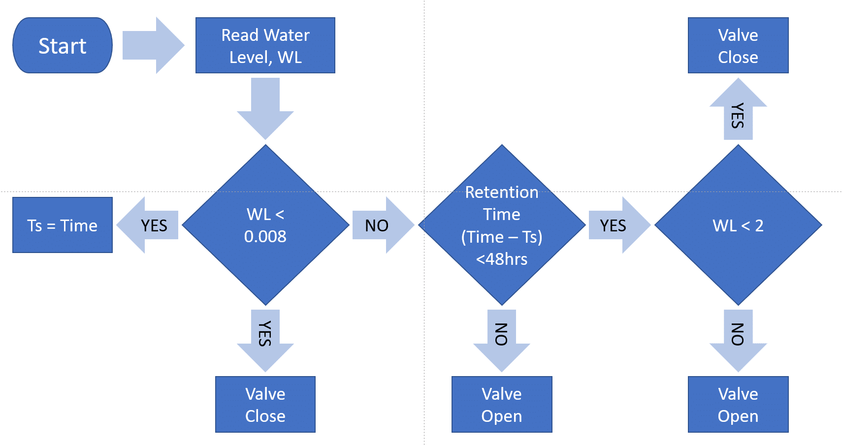
Basically trying to control flow through an outlet of a bioswale. The algorithm for control is attached as a diagram (I have written this in python and campbell coding but yet to do in C++). I’ve attached the .ino file I’m playing around with as well. The decagon CTD sensor is connected to D4-5 and I’m trying to get a 0-5V signal out from D10-11 as you suggested. And yes I need to maintain a 5V signal between sensor readings to keep the valve open according to the algorithm. I hope this clarifies what I’m trying to do.
-
-
-
AuthorPosts
- You must be logged in to reply to this topic.