
Home › Forums › Mayfly Data Logger › How to determine battery and power supply
- This topic has 6 replies, 2 voices, and was last updated 2023-09-01 at 8:42 PM by
 Braedon.
-
AuthorPosts
-
-
2023-08-30 at 9:47 AM #18039
Hi everyone, I’m wondering what is the best way to determine how much power I need to supply to run my Mayfly and the sensors attached, and how I properly size batteries and solar panels. The sensors I have attached that require power are 3 Meter Teros 12 sensors and 1 MaxBotix sonar sensor.
For the Meter sensors, the datasheet says that the supply voltage minimum is 4.0 VDC and the maximum is 15.0 VDC, and the typical current drain is 3.6 mA when taking measurements and 0.03 mA when asleep. The MaxBotix sonar’s datasheet says to operate it at 5 V for snow measurements and that the corresponding current draw is 3.1 mA. I also have an XBee module that will use about 215 mA when transmitting, and 2.5 uA when sleeping.
It should be noted that this data logging station will be deployed for the winter months in particular, which I imagine affects the batteries’ and solar panels’ performance. Is there a general rule of thumb that is a good go-to for batteries and solar panels on projects of this size?
-
2023-08-30 at 10:58 AM #18041
Standard practice is that when the Mayfly board goes to sleep in between measurements, it turns off all power supplied to the sensors and radio module. So the power consumed when sleeping is just the bare minimum to keep the Mayfly in sleep mode, which is usually a little less than 1 milliamp. There are ways to make it use even less in sleep mode, but it’s usually not necessary since the overwhelming majority of the power used is during the sensor sampling and radio transmitting time. Power-hungry sensors with motorized wipers or large current draw, and radios that need long connection times are the most challenging peripherals to use, but 3 soil moisture sensors and an unltrasonic sensor will use very little power when sampling, so they won’t stress a 4400mAh battery at all when matched with a decent solar panel like the 3.5w or 5w panels we usually recommend. I don’t know what Xbee module you’re using since they make wifi, cellular, and RF modules, but your transmit time and duty cycle will determine the overall power usage.
-
2023-08-30 at 4:13 PM #18042
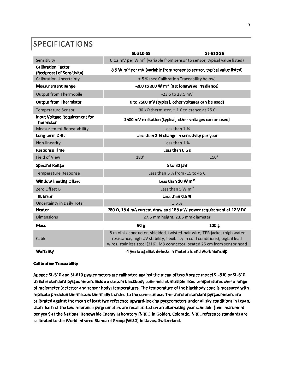
Awesome. The XBee module is an RF module, the XBee Pro S3B. I just remembered, while the apogee sensors I am using don’t require power to make measurements, they do require power for the internal heater. The pyrgeometer heaters, according to the datasheet, draw 15.4 mA and 185 mW at 12 VDC. The pyranometers draw 30.8 mA and 370s mW at 12 VDC. In total there are four apogee sensors (two pyrgeometers and two pyranometers). Do you think it is still a similar situation @shicks that the 4400 mAh battery and 5w panels are sufficient?
-
2023-08-30 at 4:27 PM #18043
Sensors with heaters are another big challenge, especially if they run continuously. Are the heaters powered all the time, or only when taking a sample? Do they require 12v to operate, or was that spec just listing the power draw at 12v?
You can do some basic battery life calculations on this handy website: https://oregonembedded.com/batterycalc.htm
-
2023-08-30 at 7:42 PM #18044
I’ve attached the specs sheet to this reply. Maybe you can help me interpret it. The following is what I was told from Apogee when I asked about the heaters:
“Regarding the heaters, you do not need to operate them all the time. If the sensors are not in an environment where snow/frost are an issue, the connections for the heater can be omitted entirely. So long as the heater connections are in use (yellow wire on the SL-610-SS), the heater will be on. The only way to turn off the heater is to disconnect the corresponding pigtail. Most people leave them on all the time if their datalogger has enough space available. Not using the heater at all will not affect readings. If the heater is constantly powered, it is able to clear frost/snow in just a couple of minutes (depending on how much).”
Since these are snow sensing stations, the heater will be needed, but as far as I understand it, they do not need to be powered constantly. Am I understanding correctly?
Attachments:
-
2023-08-31 at 6:27 PM #18054
If you’ve got 4 heated sensors that require constant 12 volts, then I don’t think the Mayfly and the standard “battery/solar panel combo” is going to be sufficient. It would be a struggle for the Mayfly to supply the necessary continuous 100ma at 12v for the heaters, in addition to powering the various sensors intermittently. You could have a separate 12v battery with it’s own 12v solar panel and charge controller to power the sensor heaters, and then use a 12v-to-5v converter to power the Mayfly via the USB jack. Then you wouldn’t have to worry about the smaller Mayfly battery and solar panel, and the bigger battery/panel combination should be sufficient for powering your whole setup.
-
2023-09-01 at 8:42 PM #18057
-
-
AuthorPosts
- You must be logged in to reply to this topic.