
Home › Forums › Mayfly Data Logger › DRWI_LTE Mayfly Communication with Monitor My Watershed
Tagged: Meter Group or Decagon?
- This topic has 5 replies, 2 voices, and was last updated 2021-03-16 at 10:46 AM by
Cheryl Nolan.
-
AuthorPosts
-
-
2021-03-12 at 11:35 AM #15241
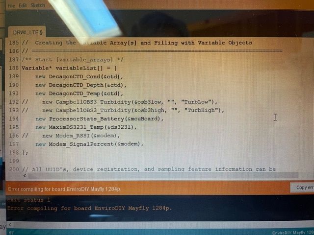
After copying text from ‘Token and UUID List’ and adding to DRWI_LTE (see screenshots), changing the logger ID, adding the slashes in front of the turbidity sensor code line etc. and changing the order of depth and temp to match Monitor My Watershed page, I’m getting an error message after hitting upload button. “Error compiling for board EnviroDIY Mayfly 1284p, exit status 1.” Any suggestions? I double checked the changes and can’t find any errors. Went through the steps a second time and I’m still getting the error message.
Thanks
Attachments:
-
2021-03-12 at 5:22 PM #15251
I’m sorry, could you paste your whole code and a more detailed error message.
-
2021-03-14 at 11:42 AM #15254
<h4>This is the error message I get:</h4>
Arduino: 1.8.13 (Windows Store 1.8.42.0) (Windows 10), Board: “EnviroDIY Mayfly 1284p”C:\Users\cnolan\Documents\Arduino\libraries\EnviroDIY_ModularSensors\src\sensors\ApogeeSQ212.cpp:15:10: fatal error: Adafruit_ADS1015.h: No such file or directory
#include <Adafruit_ADS1015.h>
^~~~~~~~~~~~~~~~~~~~
compilation terminated.
exit status 1
Error compiling for board EnviroDIY Mayfly 1284p.This report would have more information with
“Show verbose output during compilation”
option enabled in File -> Preferences.
<h4></h4>
<h4>From Monitor My Watershed monitoring site…..</h4>
<h4>Token and UUID List</h4>
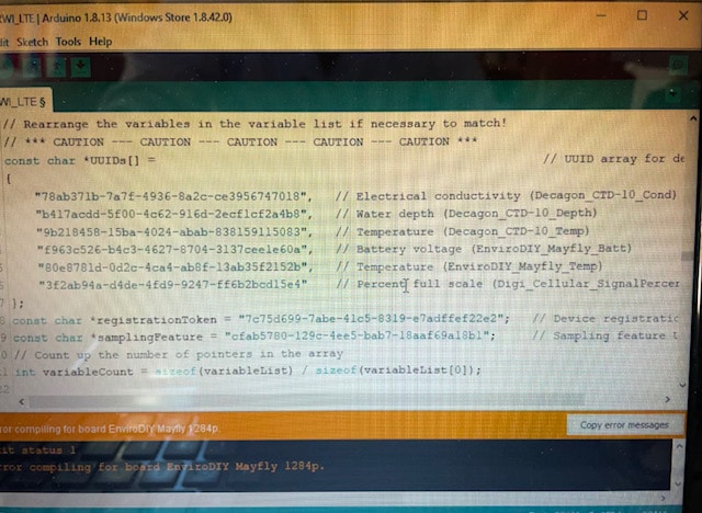
const char *UUIDs[] = // UUID array for device sensors
{
“78ab371b-7a7f-4936-8a2c-ce3956747018”, // Electrical conductivity (Decagon_CTD-10_Cond)
“b417acdd-5f00-4c62-916d-2ecf1cf2a4b8”, // Water depth (Decagon_CTD-10_Depth)
“9b218458-15ba-4024-abab-838159115083”, // Temperature (Decagon_CTD-10_Temp)
“f963c526-b4c3-4627-8704-3137cee1e60a”, // Battery voltage (EnviroDIY_Mayfly_Batt)
“80e8781d-0d2c-4ca4-ab8f-13ab35f2152b”, // Temperature (EnviroDIY_Mayfly_Temp)
“3f2ab94a-d4de-4fd9-9247-ff6b2bcd15e4” // Percent full scale (Digi_Cellular_SignalPercent)
};
const char *registrationToken = “7c75d699-7abe-41c5-8319-e7adffef22e2”; // Device registration token
const char *samplingFeature = “cfab5780-129c-4ee5-bab7-18aaf69a18b1”; // Sampling feature UUIDCurrent or original Code on Mayfly board:
/** =========================================================================
* @file DRWI_LTE.ino
* @brief Example for DRWI CitSci LTE sites.
*
* @author Sara Geleskie Damiano <sdamiano@stroudcenter.org>
* @copyright (c) 2017-2020 Stroud Water Research Center (SWRC)
* and the EnviroDIY Development Team
* This example is published under the BSD-3 license.
*
* Build Environment: Visual Studios Code with PlatformIO
* Hardware Platform: EnviroDIY Mayfly Arduino Datalogger
*
* DISCLAIMER:
* THIS CODE IS PROVIDED “AS IS” – NO WARRANTY IS GIVEN.
* ======================================================================= */// ==========================================================================
// Defines for the Arduino IDE
// NOTE: These are ONLY needed to compile with the Arduino IDE.
// If you use PlatformIO, you should set these build flags in your
// platformio.ini
// ==========================================================================
/** Start [defines] */
#ifndef TINY_GSM_RX_BUFFER
#define TINY_GSM_RX_BUFFER 64
#endif
#ifndef TINY_GSM_YIELD_MS
#define TINY_GSM_YIELD_MS 2
#endif
/** End [defines] */// ==========================================================================
// Include the libraries required for any data logger
// ==========================================================================
/** Start [includes] */
// The Arduino library is needed for every Arduino program.
#include <Arduino.h>// EnableInterrupt is used by ModularSensors for external and pin change
// interrupts and must be explicitly included in the main program.
#include <EnableInterrupt.h>// To get all of the base classes for ModularSensors, include LoggerBase.
// NOTE: Individual sensor definitions must be included separately.
#include <LoggerBase.h>
/** End [includes] */// ==========================================================================
// Data Logging Options
// ==========================================================================
/** Start [logging_options] */
// The name of this program file
const char* sketchName = “DRWI_LTE.ino”;
// Logger ID, also becomes the prefix for the name of the data file on SD card
const char* LoggerID = “XXXXX”;
// How frequently (in minutes) to log data
const uint8_t loggingInterval = 5;
// Your logger’s timezone.
const int8_t timeZone = -5; // Eastern Standard Time
// NOTE: Daylight savings time will not be applied! Please use standard time!// Set the input and output pins for the logger
// NOTE: Use -1 for pins that do not apply
const long serialBaud = 115200; // Baud rate for debugging
const int8_t greenLED = 8; // Pin for the green LED
const int8_t redLED = 9; // Pin for the red LED
const int8_t buttonPin = 21; // Pin for debugging mode (ie, button pin)
const int8_t wakePin = A7; // MCU interrupt/alarm pin to wake from sleep
// Set the wake pin to -1 if you do not want the main processor to sleep.
// In a SAMD system where you are using the built-in rtc, set wakePin to 1
const int8_t sdCardPwrPin = -1; // MCU SD card power pin
const int8_t sdCardSSPin = 12; // SD card chip select/slave select pin
const int8_t sensorPowerPin = 22; // MCU pin controlling main sensor power
/** End [logging_options] */// ==========================================================================
// Wifi/Cellular Modem Options
// ==========================================================================
/** Start [xbee_cell_transparent] */
// For any Digi Cellular XBee’s
// NOTE: The u-blox based Digi XBee’s (3G global and LTE-M global)
// are more stable used in bypass mode (below)
// The Telit based Digi XBees (LTE Cat1) can only use this mode.
#include <modems/DigiXBeeCellularTransparent.h>// Create a reference to the serial port for the modem
HardwareSerial& modemSerial = Serial1; // Use hardware serial if possible
const long modemBaud = 9600; // All XBee’s use 9600 by default// Modem Pins – Describe the physical pin connection of your modem to your board
// NOTE: Use -1 for pins that do not apply
const int8_t modemVccPin = -2; // MCU pin controlling modem power
const int8_t modemStatusPin = 19; // MCU pin used to read modem status
const bool useCTSforStatus = false; // Flag to use the modem CTS pin for status
const int8_t modemResetPin = 20; // MCU pin connected to modem reset pin
const int8_t modemSleepRqPin = 23; // MCU pin for modem sleep/wake request
const int8_t modemLEDPin = redLED; // MCU pin connected an LED to show modem
// status (-1 if unconnected)// Network connection information
const char* apn = “hologram”; // The APN for the gprs connectionDigiXBeeCellularTransparent modemXBCT(&modemSerial, modemVccPin, modemStatusPin,
useCTSforStatus, modemResetPin,
modemSleepRqPin, apn);
// Create an extra reference to the modem by a generic name
DigiXBeeCellularTransparent modem = modemXBCT;
/** End [xbee_cell_transparent] */// ==========================================================================
// Using the Processor as a Sensor
// ==========================================================================
/** Start [processor_sensor] */
#include <sensors/ProcessorStats.h>// Create the main processor chip “sensor” – for general metadata
const char* mcuBoardVersion = “v0.5b”;
ProcessorStats mcuBoard(mcuBoardVersion);
/** End [processor_sensor] */// ==========================================================================
// Maxim DS3231 RTC (Real Time Clock)
// ==========================================================================
/** Start [ds3231] */
#include <sensors/MaximDS3231.h>// Create a DS3231 sensor object
MaximDS3231 ds3231(1);
/** End [ds3231] */// ==========================================================================
// Campbell OBS 3 / OBS 3+ Analog Turbidity Sensor
// ==========================================================================
/** Start [obs3] */
#include <sensors/CampbellOBS3.h>const int8_t OBS3Power = sensorPowerPin; // Power pin (-1 if unconnected)
const uint8_t OBS3NumberReadings = 10;
const uint8_t ADSi2c_addr = 0x48; // The I2C address of the ADS1115 ADC
// Campbell OBS 3+ *Low* Range Calibration in Volts
const int8_t OBSLowADSChannel = 0; // ADS channel for *low* range output
const float OBSLow_A = 0.000E+00; // “A” value (X^2) [*low* range]
const float OBSLow_B = 1.000E+00; // “B” value (X) [*low* range]
const float OBSLow_C = 0.000E+00; // “C” value [*low* range]// Create a Campbell OBS3+ *low* range sensor object
CampbellOBS3 osb3low(OBS3Power, OBSLowADSChannel, OBSLow_A, OBSLow_B, OBSLow_C,
ADSi2c_addr, OBS3NumberReadings);// Campbell OBS 3+ *High* Range Calibration in Volts
const int8_t OBSHighADSChannel = 1; // ADS channel for *high* range output
const float OBSHigh_A = 0.000E+00; // “A” value (X^2) [*high* range]
const float OBSHigh_B = 1.000E+00; // “B” value (X) [*high* range]
const float OBSHigh_C = 0.000E+00; // “C” value [*high* range]// Create a Campbell OBS3+ *high* range sensor object
CampbellOBS3 osb3high(OBS3Power, OBSHighADSChannel, OBSHigh_A, OBSHigh_B,
OBSHigh_C, ADSi2c_addr, OBS3NumberReadings);
/** End [obs3] */// ==========================================================================
// Meter Hydros 21 Conductivity, Temperature, and Depth Sensor
// ==========================================================================
/** Start [decagon_ctd] */
#include <sensors/DecagonCTD.h>const char* CTDSDI12address = “1”; // The SDI-12 Address of the CTD
const uint8_t CTDNumberReadings = 6; // The number of readings to average
const int8_t SDI12Power = sensorPowerPin; // Power pin (-1 if unconnected)
const int8_t SDI12Data = 7; // The SDI12 data pin// Create a Decagon CTD sensor object
DecagonCTD ctd(*CTDSDI12address, SDI12Power, SDI12Data, CTDNumberReadings);
/** End [decagon_ctd] */// ==========================================================================
// Creating the Variable Array[s] and Filling with Variable Objects
// ==========================================================================
/** Start [variable_arrays] */
Variable* variableList[] = {
new DecagonCTD_Cond(&ctd),
new DecagonCTD_Temp(&ctd),
new DecagonCTD_Depth(&ctd),
new CampbellOBS3_Turbidity(&osb3low, “”, “TurbLow”),
new CampbellOBS3_Turbidity(&osb3high, “”, “TurbHigh”),
new ProcessorStats_Battery(&mcuBoard),
new MaximDS3231_Temp(&ds3231),
new Modem_RSSI(&modem),
new Modem_SignalPercent(&modem),
};// All UUID’s, device registration, and sampling feature information can be
// pasted directly from Monitor My Watershed. To get the list, click the “View
// token UUID list” button on the upper right of the site page.// *** CAUTION — CAUTION — CAUTION — CAUTION — CAUTION ***
// Check the order of your variables in the variable list!!!
// Be VERY certain that they match the order of your UUID’s!
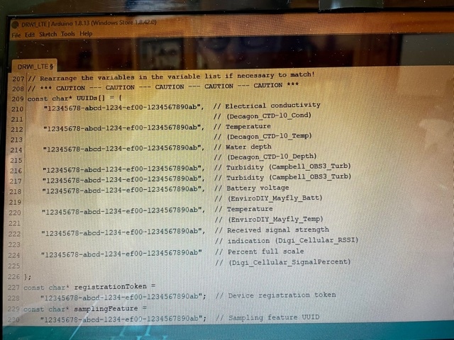
// Rearrange the variables in the variable list if necessary to match!
// *** CAUTION — CAUTION — CAUTION — CAUTION — CAUTION ***
const char* UUIDs[] = {
“12345678-abcd-1234-ef00-1234567890ab”, // Electrical conductivity
// (Decagon_CTD-10_Cond)
“12345678-abcd-1234-ef00-1234567890ab”, // Temperature
// (Decagon_CTD-10_Temp)
“12345678-abcd-1234-ef00-1234567890ab”, // Water depth
// (Decagon_CTD-10_Depth)
“12345678-abcd-1234-ef00-1234567890ab”, // Turbidity (Campbell_OBS3_Turb)
“12345678-abcd-1234-ef00-1234567890ab”, // Turbidity (Campbell_OBS3_Turb)
“12345678-abcd-1234-ef00-1234567890ab”, // Battery voltage
// (EnviroDIY_Mayfly_Batt)
“12345678-abcd-1234-ef00-1234567890ab”, // Temperature
// (EnviroDIY_Mayfly_Temp)
“12345678-abcd-1234-ef00-1234567890ab”, // Received signal strength
// indication (Digi_Cellular_RSSI)
“12345678-abcd-1234-ef00-1234567890ab” // Percent full scale
// (Digi_Cellular_SignalPercent)
};
const char* registrationToken =
“12345678-abcd-1234-ef00-1234567890ab”; // Device registration token
const char* samplingFeature =
“12345678-abcd-1234-ef00-1234567890ab”; // Sampling feature UUID// Count up the number of pointers in the array
int variableCount = sizeof(variableList) / sizeof(variableList[0]);// Create the VariableArray object
VariableArray varArray(variableCount, variableList, UUIDs);
/** End [variable_arrays] */// ==========================================================================
// The Logger Object[s]
// ==========================================================================
/** Start [loggers] */
// Create a new logger instance
Logger dataLogger(LoggerID, loggingInterval, &varArray);
/** End [loggers] */// ==========================================================================
// Creating Data Publisher[s]
// ==========================================================================
/** Start [publishers] */
// Create a data publisher for the Monitor My Watershed/EnviroDIY POST endpoint
#include <publishers/EnviroDIYPublisher.h>
EnviroDIYPublisher EnviroDIYPOST(dataLogger, &modem.gsmClient,
registrationToken, samplingFeature);
/** End [publishers] */// ==========================================================================
// Working Functions
// ==========================================================================
/** Start [working_functions] */
// Flashes the LED’s on the primary board
void greenredflash(uint8_t numFlash = 4, uint8_t rate = 75) {
for (uint8_t i = 0; i < numFlash; i++) {
digitalWrite(greenLED, HIGH);
digitalWrite(redLED, LOW);
delay(rate);
digitalWrite(greenLED, LOW);
digitalWrite(redLED, HIGH);
delay(rate);
}
digitalWrite(redLED, LOW);
}// Reads the battery voltage
// NOTE: This will actually return the battery level from the previous update!
float getBatteryVoltage() {
if (mcuBoard.sensorValues[0] == -9999) mcuBoard.update();
return mcuBoard.sensorValues[0];
}// ==========================================================================
// Arduino Setup Function
// ==========================================================================
/** Start [setup] */
void setup() {
// Start the primary serial connection
Serial.begin(serialBaud);// Print a start-up note to the first serial port
Serial.print(F(“Now running “));
Serial.print(sketchName);
Serial.print(F(” on Logger “));
Serial.println(LoggerID);
Serial.println();Serial.print(F(“Using ModularSensors Library version “));
Serial.println(MODULAR_SENSORS_VERSION);
Serial.print(F(“TinyGSM Library version “));
Serial.println(TINYGSM_VERSION);
Serial.println();// Start the serial connection with the modem
modemSerial.begin(modemBaud);// Set up pins for the LED’s
pinMode(greenLED, OUTPUT);
digitalWrite(greenLED, LOW);
pinMode(redLED, OUTPUT);
digitalWrite(redLED, LOW);
// Blink the LEDs to show the board is on and starting up
greenredflash();// Set the timezones for the logger/data and the RTC
// Logging in the given time zone
Logger::setLoggerTimeZone(timeZone);
// It is STRONGLY RECOMMENDED that you set the RTC to be in UTC (UTC+0)
Logger::setRTCTimeZone(0);// Attach the modem and information pins to the logger
dataLogger.attachModem(modem);
modem.setModemLED(modemLEDPin);
dataLogger.setLoggerPins(wakePin, sdCardSSPin, sdCardPwrPin, buttonPin,
greenLED);// Begin the logger
dataLogger.begin();// Note: Please change these battery voltages to match your battery
// Set up the sensors, except at lowest battery level
if (getBatteryVoltage() > 3.4) {
Serial.println(F(“Setting up sensors…”));
varArray.setupSensors();
}// Extra modem set-up – selecting AT&T as the carrier and LTE-M only
// NOTE: The code for this could be shortened using the “commandMode” and
// other XBee specific commands in TinyGSM. I’ve written it this way in
// this example to show how the settings could be changed in either bypass
// OR transparent mode.
Serial.println(F(“Waking modem and setting Cellular Carrier Options…”));
modem.modemWake(); // NOTE: This will also set up the modem
// Go back to command mode to set carrier options
for (uint8_t i = 0; i < 5; i++) {
// Wait the required guard time before entering command mode
delay(1010);
modem.gsmModem.streamWrite(GF(“+++”)); // enter command mode
if (modem.gsmModem.waitResponse(2000, GF(“OK\r”)) == 1) break;
}
// Carrier Profile – 0 = Automatic selection
// – 1 = No profile/SIM ICCID selected
// – 2 = AT&T
// – 3 = Verizon
// NOTE: To select T-Mobile, you must enter bypass mode!
modem.gsmModem.sendAT(GF(“CP”), 2);
modem.gsmModem.waitResponse(GF(“OK\r”));
// Cellular network technology – 0 = LTE-M with NB-IoT fallback
// – 1 = NB-IoT with LTE-M fallback
// – 2 = LTE-M only
// – 3 = NB-IoT only
modem.gsmModem.sendAT(GF(“N#”), 2);
modem.gsmModem.waitResponse();
// Write changes to flash and apply them
Serial.println(F(“Wait while applying changes…”));
// Write changes to flash
modem.gsmModem.sendAT(GF(“WR”));
modem.gsmModem.waitResponse(GF(“OK\r”));
// Apply changes
modem.gsmModem.sendAT(GF(“AC”));
modem.gsmModem.waitResponse(GF(“OK\r”));
// Reset the cellular component to ensure network settings are changed
modem.gsmModem.sendAT(GF(“!R”));
modem.gsmModem.waitResponse(30000L, GF(“OK\r”));
// Force reset of the Digi component as well
// This effectively exits command mode
modem.gsmModem.sendAT(GF(“FR”));
modem.gsmModem.waitResponse(5000L, GF(“OK\r”));// Sync the clock if it isn’t valid or we have battery to spare
if (getBatteryVoltage() > 3.55 || !dataLogger.isRTCSane()) {
// Synchronize the RTC with NIST
// This will also set up the modem
dataLogger.syncRTC();
}// Create the log file, adding the default header to it
// Do this last so we have the best chance of getting the time correct and
// all sensor names correct
// Writing to the SD card can be power intensive, so if we’re skipping
// the sensor setup we’ll skip this too.
if (getBatteryVoltage() > 3.4) {
Serial.println(F(“Setting up file on SD card”));
dataLogger.turnOnSDcard(
true); // true = wait for card to settle after power up
dataLogger.createLogFile(true); // true = write a new header
dataLogger.turnOffSDcard(
true); // true = wait for internal housekeeping after write
}// Call the processor sleep
Serial.println(F(“Putting processor to sleep\n”));
dataLogger.systemSleep();
}
/** End [setup] */// ==========================================================================
// Arduino Loop Function
// ==========================================================================
/** Start [loop] */
// Use this short loop for simple data logging and sending
void loop() {
// Note: Please change these battery voltages to match your battery
// At very low battery, just go back to sleep
if (getBatteryVoltage() < 3.4) {
dataLogger.systemSleep();
}
// At moderate voltage, log data but don’t send it over the modem
else if (getBatteryVoltage() < 3.55) {
dataLogger.logData();
}
// If the battery is good, send the data to the world
else {
dataLogger.logDataAndPublish();
}
}
/** End [loop] */After Changes…….
/** =========================================================================
* @file DRWI_LTE.ino
* @brief Example for DRWI CitSci LTE sites.
*
* @author Sara Geleskie Damiano <sdamiano@stroudcenter.org>
* @copyright (c) 2017-2020 Stroud Water Research Center (SWRC)
* and the EnviroDIY Development Team
* This example is published under the BSD-3 license.
*
* Build Environment: Visual Studios Code with PlatformIO
* Hardware Platform: EnviroDIY Mayfly Arduino Datalogger
*
* DISCLAIMER:
* THIS CODE IS PROVIDED “AS IS” – NO WARRANTY IS GIVEN.
* ======================================================================= */// ==========================================================================
// Defines for the Arduino IDE
// NOTE: These are ONLY needed to compile with the Arduino IDE.
// If you use PlatformIO, you should set these build flags in your
// platformio.ini
// ==========================================================================
/** Start [defines] */
#ifndef TINY_GSM_RX_BUFFER
#define TINY_GSM_RX_BUFFER 64
#endif
#ifndef TINY_GSM_YIELD_MS
#define TINY_GSM_YIELD_MS 2
#endif
/** End [defines] */// ==========================================================================
// Include the libraries required for any data logger
// ==========================================================================
/** Start [includes] */
// The Arduino library is needed for every Arduino program.
#include <Arduino.h>// EnableInterrupt is used by ModularSensors for external and pin change
// interrupts and must be explicitly included in the main program.
#include <EnableInterrupt.h>// To get all of the base classes for ModularSensors, include LoggerBase.
// NOTE: Individual sensor definitions must be included separately.
#include <LoggerBase.h>
/** End [includes] */// ==========================================================================
// Data Logging Options
// ==========================================================================
/** Start [logging_options] */
// The name of this program file
const char* sketchName = “DRWI_LTE.ino”;
// Logger ID, also becomes the prefix for the name of the data file on SD card
const char* LoggerID = “Lack2_Arch”;
// How frequently (in minutes) to log data
const uint8_t loggingInterval = 5;
// Your logger’s timezone.
const int8_t timeZone = -5; // Eastern Standard Time
// NOTE: Daylight savings time will not be applied! Please use standard time!// Set the input and output pins for the logger
// NOTE: Use -1 for pins that do not apply
const long serialBaud = 115200; // Baud rate for debugging
const int8_t greenLED = 8; // Pin for the green LED
const int8_t redLED = 9; // Pin for the red LED
const int8_t buttonPin = 21; // Pin for debugging mode (ie, button pin)
const int8_t wakePin = A7; // MCU interrupt/alarm pin to wake from sleep
// Set the wake pin to -1 if you do not want the main processor to sleep.
// In a SAMD system where you are using the built-in rtc, set wakePin to 1
const int8_t sdCardPwrPin = -1; // MCU SD card power pin
const int8_t sdCardSSPin = 12; // SD card chip select/slave select pin
const int8_t sensorPowerPin = 22; // MCU pin controlling main sensor power
/** End [logging_options] */// ==========================================================================
// Wifi/Cellular Modem Options
// ==========================================================================
/** Start [xbee_cell_transparent] */
// For any Digi Cellular XBee’s
// NOTE: The u-blox based Digi XBee’s (3G global and LTE-M global)
// are more stable used in bypass mode (below)
// The Telit based Digi XBees (LTE Cat1) can only use this mode.
#include <modems/DigiXBeeCellularTransparent.h>// Create a reference to the serial port for the modem
HardwareSerial& modemSerial = Serial1; // Use hardware serial if possible
const long modemBaud = 9600; // All XBee’s use 9600 by default// Modem Pins – Describe the physical pin connection of your modem to your board
// NOTE: Use -1 for pins that do not apply
const int8_t modemVccPin = -2; // MCU pin controlling modem power
const int8_t modemStatusPin = 19; // MCU pin used to read modem status
const bool useCTSforStatus = false; // Flag to use the modem CTS pin for status
const int8_t modemResetPin = 20; // MCU pin connected to modem reset pin
const int8_t modemSleepRqPin = 23; // MCU pin for modem sleep/wake request
const int8_t modemLEDPin = redLED; // MCU pin connected an LED to show modem
// status (-1 if unconnected)// Network connection information
const char* apn = “hologram”; // The APN for the gprs connectionDigiXBeeCellularTransparent modemXBCT(&modemSerial, modemVccPin, modemStatusPin,
useCTSforStatus, modemResetPin,
modemSleepRqPin, apn);
// Create an extra reference to the modem by a generic name
DigiXBeeCellularTransparent modem = modemXBCT;
/** End [xbee_cell_transparent] */// ==========================================================================
// Using the Processor as a Sensor
// ==========================================================================
/** Start [processor_sensor] */
#include <sensors/ProcessorStats.h>// Create the main processor chip “sensor” – for general metadata
const char* mcuBoardVersion = “v0.5b”;
ProcessorStats mcuBoard(mcuBoardVersion);
/** End [processor_sensor] */// ==========================================================================
// Maxim DS3231 RTC (Real Time Clock)
// ==========================================================================
/** Start [ds3231] */
#include <sensors/MaximDS3231.h>// Create a DS3231 sensor object
MaximDS3231 ds3231(1);
/** End [ds3231] */// ==========================================================================
// Campbell OBS 3 / OBS 3+ Analog Turbidity Sensor
// ==========================================================================
/** Start [obs3] */
#include <sensors/CampbellOBS3.h>const int8_t OBS3Power = sensorPowerPin; // Power pin (-1 if unconnected)
const uint8_t OBS3NumberReadings = 10;
const uint8_t ADSi2c_addr = 0x48; // The I2C address of the ADS1115 ADC
// Campbell OBS 3+ *Low* Range Calibration in Volts
const int8_t OBSLowADSChannel = 0; // ADS channel for *low* range output
const float OBSLow_A = 0.000E+00; // “A” value (X^2) [*low* range]
const float OBSLow_B = 1.000E+00; // “B” value (X) [*low* range]
const float OBSLow_C = 0.000E+00; // “C” value [*low* range]// Create a Campbell OBS3+ *low* range sensor object
CampbellOBS3 osb3low(OBS3Power, OBSLowADSChannel, OBSLow_A, OBSLow_B, OBSLow_C,
ADSi2c_addr, OBS3NumberReadings);// Campbell OBS 3+ *High* Range Calibration in Volts
const int8_t OBSHighADSChannel = 1; // ADS channel for *high* range output
const float OBSHigh_A = 0.000E+00; // “A” value (X^2) [*high* range]
const float OBSHigh_B = 1.000E+00; // “B” value (X) [*high* range]
const float OBSHigh_C = 0.000E+00; // “C” value [*high* range]// Create a Campbell OBS3+ *high* range sensor object
CampbellOBS3 osb3high(OBS3Power, OBSHighADSChannel, OBSHigh_A, OBSHigh_B,
OBSHigh_C, ADSi2c_addr, OBS3NumberReadings);
/** End [obs3] */// ==========================================================================
// Meter Hydros 21 Conductivity, Temperature, and Depth Sensor
// ==========================================================================
/** Start [decagon_ctd] */
#include <sensors/DecagonCTD.h>const char* CTDSDI12address = “1”; // The SDI-12 Address of the CTD
const uint8_t CTDNumberReadings = 6; // The number of readings to average
const int8_t SDI12Power = sensorPowerPin; // Power pin (-1 if unconnected)
const int8_t SDI12Data = 7; // The SDI12 data pin// Create a Decagon CTD sensor object
DecagonCTD ctd(*CTDSDI12address, SDI12Power, SDI12Data, CTDNumberReadings);
/** End [decagon_ctd] */// ==========================================================================
// Creating the Variable Array[s] and Filling with Variable Objects
// ==========================================================================
/** Start [variable_arrays] */
Variable* variableList[] = {
new DecagonCTD_Cond(&ctd),
new DecagonCTD_Depth(&ctd),
new DecagonCTD_Temp(&ctd),
// new CampbellOBS3_Turbidity(&osb3low, “”, “TurbLow”),
// new CampbellOBS3_Turbidity(&osb3high, “”, “TurbHigh”),
new ProcessorStats_Battery(&mcuBoard),
new MaximDS3231_Temp(&ds3231),
// new Modem_RSSI(&modem),
new Modem_SignalPercent(&modem),
};// All UUID’s, device registration, and sampling feature information can be
// pasted directly from Monitor My Watershed. To get the list, click the “View
// token UUID list” button on the upper right of the site page.// *** CAUTION — CAUTION — CAUTION — CAUTION — CAUTION ***
// Check the order of your variables in the variable list!!!
// Be VERY certain that they match the order of your UUID’s!
// Rearrange the variables in the variable list if necessary to match!
// *** CAUTION — CAUTION — CAUTION — CAUTION — CAUTION ***
const char *UUIDs[] = // UUID array for device sensors
{
“78ab371b-7a7f-4936-8a2c-ce3956747018”, // Electrical conductivity (Decagon_CTD-10_Cond)
“b417acdd-5f00-4c62-916d-2ecf1cf2a4b8”, // Water depth (Decagon_CTD-10_Depth)
“9b218458-15ba-4024-abab-838159115083”, // Temperature (Decagon_CTD-10_Temp)
“f963c526-b4c3-4627-8704-3137cee1e60a”, // Battery voltage (EnviroDIY_Mayfly_Batt)
“80e8781d-0d2c-4ca4-ab8f-13ab35f2152b”, // Temperature (EnviroDIY_Mayfly_Temp)
“3f2ab94a-d4de-4fd9-9247-ff6b2bcd15e4” // Percent full scale (Digi_Cellular_SignalPercent)
};
const char *registrationToken = “7c75d699-7abe-41c5-8319-e7adffef22e2”; // Device registration token
const char *samplingFeature = “cfab5780-129c-4ee5-bab7-18aaf69a18b1”; // Sampling feature UUID
// Count up the number of pointers in the array
int variableCount = sizeof(variableList) / sizeof(variableList[0]);// Create the VariableArray object
VariableArray varArray(variableCount, variableList, UUIDs);
/** End [variable_arrays] */// ==========================================================================
// The Logger Object[s]
// ==========================================================================
/** Start [loggers] */
// Create a new logger instance
Logger dataLogger(LoggerID, loggingInterval, &varArray);
/** End [loggers] */// ==========================================================================
// Creating Data Publisher[s]
// ==========================================================================
/** Start [publishers] */
// Create a data publisher for the Monitor My Watershed/EnviroDIY POST endpoint
#include <publishers/EnviroDIYPublisher.h>
EnviroDIYPublisher EnviroDIYPOST(dataLogger, &modem.gsmClient,
registrationToken, samplingFeature);
/** End [publishers] */// ==========================================================================
// Working Functions
// ==========================================================================
/** Start [working_functions] */
// Flashes the LED’s on the primary board
void greenredflash(uint8_t numFlash = 4, uint8_t rate = 75) {
for (uint8_t i = 0; i < numFlash; i++) {
digitalWrite(greenLED, HIGH);
digitalWrite(redLED, LOW);
delay(rate);
digitalWrite(greenLED, LOW);
digitalWrite(redLED, HIGH);
delay(rate);
}
digitalWrite(redLED, LOW);
}// Reads the battery voltage
// NOTE: This will actually return the battery level from the previous update!
float getBatteryVoltage() {
if (mcuBoard.sensorValues[0] == -9999) mcuBoard.update();
return mcuBoard.sensorValues[0];
}// ==========================================================================
// Arduino Setup Function
// ==========================================================================
/** Start [setup] */
void setup() {
// Start the primary serial connection
Serial.begin(serialBaud);// Print a start-up note to the first serial port
Serial.print(F(“Now running “));
Serial.print(sketchName);
Serial.print(F(” on Logger “));
Serial.println(LoggerID);
Serial.println();Serial.print(F(“Using ModularSensors Library version “));
Serial.println(MODULAR_SENSORS_VERSION);
Serial.print(F(“TinyGSM Library version “));
Serial.println(TINYGSM_VERSION);
Serial.println();// Start the serial connection with the modem
modemSerial.begin(modemBaud);// Set up pins for the LED’s
pinMode(greenLED, OUTPUT);
digitalWrite(greenLED, LOW);
pinMode(redLED, OUTPUT);
digitalWrite(redLED, LOW);
// Blink the LEDs to show the board is on and starting up
greenredflash();// Set the timezones for the logger/data and the RTC
// Logging in the given time zone
Logger::setLoggerTimeZone(timeZone);
// It is STRONGLY RECOMMENDED that you set the RTC to be in UTC (UTC+0)
Logger::setRTCTimeZone(0);// Attach the modem and information pins to the logger
dataLogger.attachModem(modem);
modem.setModemLED(modemLEDPin);
dataLogger.setLoggerPins(wakePin, sdCardSSPin, sdCardPwrPin, buttonPin,
greenLED);// Begin the logger
dataLogger.begin();// Note: Please change these battery voltages to match your battery
// Set up the sensors, except at lowest battery level
if (getBatteryVoltage() > 3.4) {
Serial.println(F(“Setting up sensors…”));
varArray.setupSensors();
}// Extra modem set-up – selecting AT&T as the carrier and LTE-M only
// NOTE: The code for this could be shortened using the “commandMode” and
// other XBee specific commands in TinyGSM. I’ve written it this way in
// this example to show how the settings could be changed in either bypass
// OR transparent mode.
Serial.println(F(“Waking modem and setting Cellular Carrier Options…”));
modem.modemWake(); // NOTE: This will also set up the modem
// Go back to command mode to set carrier options
for (uint8_t i = 0; i < 5; i++) {
// Wait the required guard time before entering command mode
delay(1010);
modem.gsmModem.streamWrite(GF(“+++”)); // enter command mode
if (modem.gsmModem.waitResponse(2000, GF(“OK\r”)) == 1) break;
}
// Carrier Profile – 0 = Automatic selection
// – 1 = No profile/SIM ICCID selected
// – 2 = AT&T
// – 3 = Verizon
// NOTE: To select T-Mobile, you must enter bypass mode!
modem.gsmModem.sendAT(GF(“CP”), 2);
modem.gsmModem.waitResponse(GF(“OK\r”));
// Cellular network technology – 0 = LTE-M with NB-IoT fallback
// – 1 = NB-IoT with LTE-M fallback
// – 2 = LTE-M only
// – 3 = NB-IoT only
modem.gsmModem.sendAT(GF(“N#”), 2);
modem.gsmModem.waitResponse();
// Write changes to flash and apply them
Serial.println(F(“Wait while applying changes…”));
// Write changes to flash
modem.gsmModem.sendAT(GF(“WR”));
modem.gsmModem.waitResponse(GF(“OK\r”));
// Apply changes
modem.gsmModem.sendAT(GF(“AC”));
modem.gsmModem.waitResponse(GF(“OK\r”));
// Reset the cellular component to ensure network settings are changed
modem.gsmModem.sendAT(GF(“!R”));
modem.gsmModem.waitResponse(30000L, GF(“OK\r”));
// Force reset of the Digi component as well
// This effectively exits command mode
modem.gsmModem.sendAT(GF(“FR”));
modem.gsmModem.waitResponse(5000L, GF(“OK\r”));// Sync the clock if it isn’t valid or we have battery to spare
if (getBatteryVoltage() > 3.55 || !dataLogger.isRTCSane()) {
// Synchronize the RTC with NIST
// This will also set up the modem
dataLogger.syncRTC();
}// Create the log file, adding the default header to it
// Do this last so we have the best chance of getting the time correct and
// all sensor names correct
// Writing to the SD card can be power intensive, so if we’re skipping
// the sensor setup we’ll skip this too.
if (getBatteryVoltage() > 3.4) {
Serial.println(F(“Setting up file on SD card”));
dataLogger.turnOnSDcard(
true); // true = wait for card to settle after power up
dataLogger.createLogFile(true); // true = write a new header
dataLogger.turnOffSDcard(
true); // true = wait for internal housekeeping after write
}// Call the processor sleep
Serial.println(F(“Putting processor to sleep\n”));
dataLogger.systemSleep();
}
/** End [setup] */// ==========================================================================
// Arduino Loop Function
// ==========================================================================
/** Start [loop] */
// Use this short loop for simple data logging and sending
void loop() {
// Note: Please change these battery voltages to match your battery
// At very low battery, just go back to sleep
if (getBatteryVoltage() < 3.4) {
dataLogger.systemSleep();
}
// At moderate voltage, log data but don’t send it over the modem
else if (getBatteryVoltage() < 3.55) {
dataLogger.logData();
}
// If the battery is good, send the data to the world
else {
dataLogger.logDataAndPublish();
}
}
/** End [loop] */-
2021-03-15 at 4:49 PM #15257
Sara,
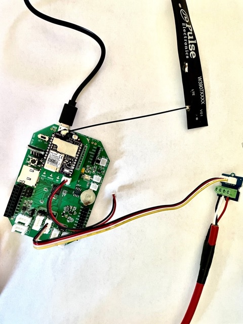
I thought I had found the problem but, I was wrong. However, to be honest I don’t know if I have a Decagon CTD-10 or a Meter Group Hydros 21. My invoice calls out a “CTD-10Hydros 21”. The Quick Start Guide calls out a Decagon CTD-10 but I thought I ordered a Meter Group Hydros 21. I have no idea if this even makes a difference.
-
-
2021-03-15 at 4:55 PM #15258
For the code, it makes no difference if it’s a Hydros21 or a CTD-10. The change between them is name-only.
Did you install all of the libraries from either the libraries repository or the ModularSensors release? You need to unzip the libraries into your Arduino user folder. The error you’re getting is saying that the compiler can’t find one of them.
-
2021-03-16 at 10:46 AM #15263
Ok, thank you. I will check.
-
-
AuthorPosts
- You must be logged in to reply to this topic.