
Home › Forums › Environmental Sensors › DFRobot Gravity KIT0139 Depth Sensor – Routine Interference?
- This topic has 5 replies, 4 voices, and was last updated 2020-11-16 at 4:54 PM by
 Matt Barney.
-
AuthorPosts
-
-
2020-11-15 at 3:34 PM #14819
Hi Everyone,
I am testing a number of low-cost sensors, one of them being the DFRobot Gravity KIT0130 water level sensor (~40USD) (https://www.dfrobot.com/product-1863.html). This requires 12-24V so we link it to an external solar panel circuit (i.e. a standard battery/solar panel/solar regulator set up), with the current being converted to voltage (read by the mayfly) via a current to voltage converter that is supplied with the product.
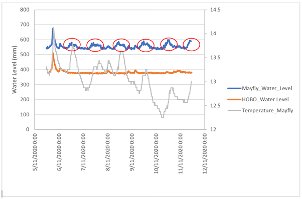
The results of my field test are in the attached image. Overall, the record looks pretty good, however there seems to be routine interference during daylight hours versus the HOBO depth logger (red circles). This makes me think that the interference is either water temperature, or interference from the solar panel. The temperature record is also attached and does not seem to show perfect correlation with the interference pattern I see in the depth record.
Does anyone have any thoughts on what might be causing this? The sensor does not adjust for temperature variation, is there a prescribed method to do this so I can eliminate temperature variation as a factor?
Thanks for your help.
James
Attachments:
-
2020-11-15 at 10:13 PM #14821
Hi James, very interesting. I wonder which Analog port on the mayfly you are using, ADS1115.?
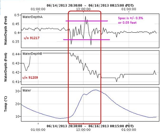
One test I do, to verify the sensors response, is put the sensor in a simulated stationery stream, (jug of water) with a solar aspect, stable power supply voltage, and measure water temperature and water temperature together and see what it reports.
Water temperature sensors https://www.seeedstudio.com/One-Wire-Temperature-Sensor-p-1235.html
These sensors typically use a varying resistance with pressure change (water depth) and are influenced by temperature. I’ve seen some sensors that have nonlinear changes with temperature – depends on internal algorithms. The KIT0130 states it has temperature compensation, but not what the range is – but who can complain at the price.
Eyeballing your graph – its +-/10mm – but whats the temperature change. 🙂
One set of measurements I did on two individual sensors that where in the same family, with a stated temperature specification showed the non-linearity in some of the sensors. They where returned.
Attachments:
-
2020-11-16 at 10:45 AM #14824
Could it possibly be a problem with the temperature inside your logger box rather than the water temperature? Maybe Shannon can pipe in and confirm, but I remember that we used to have issues like this when we were using black boxes with clear lids facing summer sun. I think the Mayfly’s ADC starts acting up when it gets too hot. Are you recording the Mayfly’s DS3231 temperature? It might show something.
I haven’t found a way to re-temperature-correct a depth sensor that’s built-in temperature correction has gone awry.
-
2020-11-16 at 2:30 PM #14835
Hi all,
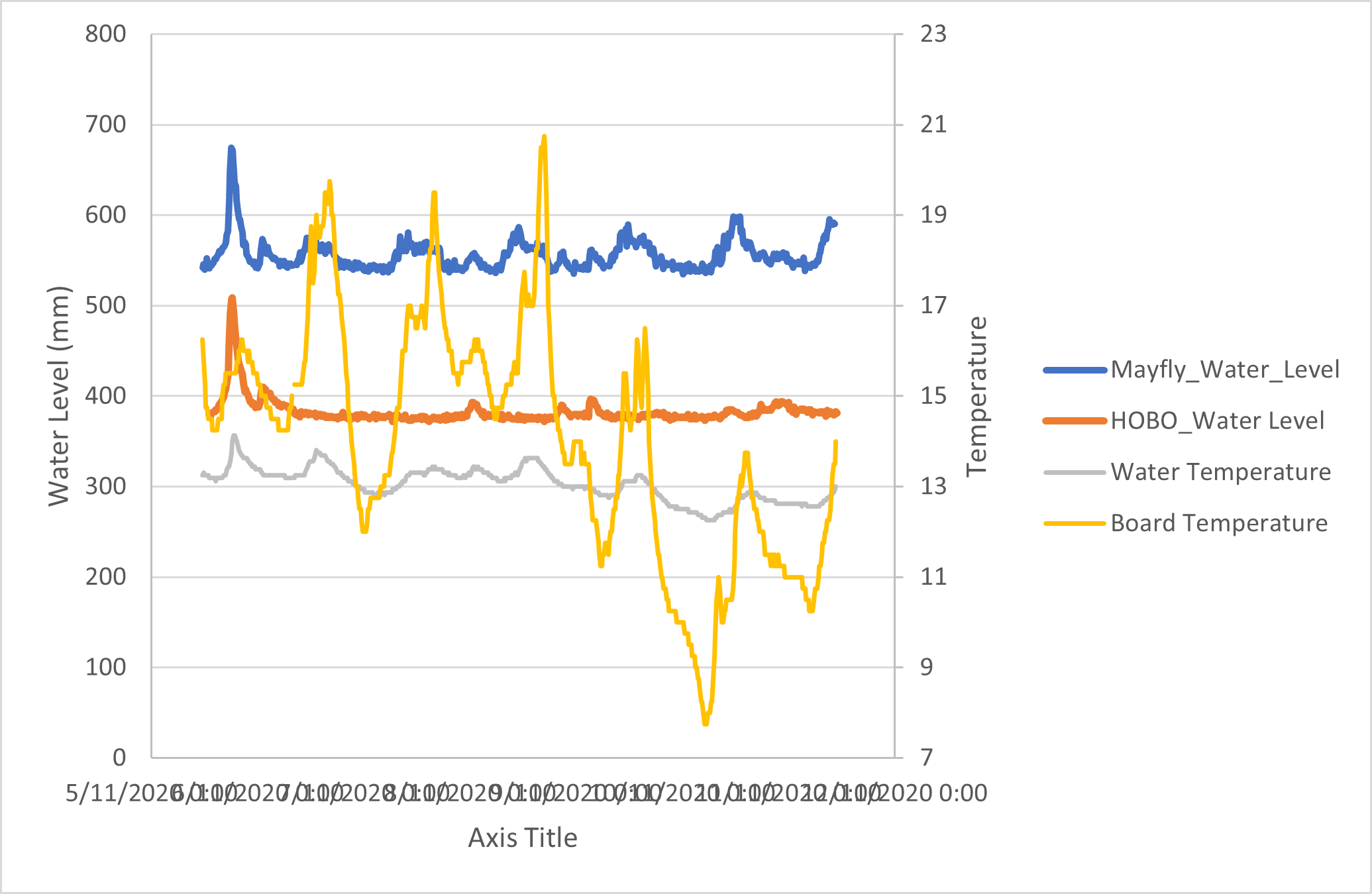
Yes we are using the ADS1115. The board temperature (DS3231) in the box is plotted in yellow below.
James
Attachments:
-
2020-11-16 at 2:49 PM #14839
Those temperature shouldn’t be a problem. If I remember right, one of our first box iterations ended up acting like a little greenhouse and turning into an oven in the summer.
Could it be the amp-to-volt board that’s the problem instead of the sensor? Do you have a second one you could test against?
-
2020-11-16 at 4:54 PM #14840
It would be interesting to see if the anomalies in sync with periods when the Mayfly’s battery voltage is peaking, i.e., during maximum solar input.
It sounds like you have the sensor on a separate circuit from the Mayfly. If that’s the case, should the grounds tied together between these two circuits? I’m not an electrical engineer, so I don’t know – just throwing it out there.
Matt
-
-
AuthorPosts
- You must be logged in to reply to this topic.