
Home › Forums › Environmental Sensors › Bizarre eTape Sensor Behaviour
- This topic has 7 replies, 3 voices, and was last updated 2021-03-24 at 2:01 PM by
 neilh20.
-
AuthorPosts
-
-
2021-03-17 at 8:53 PM #15274
Hi all,
I have been trying to calibrate an 80cm eTape sensor – standard linear resistance to voltage module (https://img1.wsimg.com/blobby/go/6e1bce17-f4fa-40c3-9d89-9bb7445697bb/downloads/0-5V%20Module%20Data%20Sheet.pdf).
Everything seems normal and there is a nice relationship between depth and voltage until I reach 40cm. At that point the voltage switches from a positive voltage to a negative voltage which subsequently increases with depth again.
I think this might have something to do with the 3.3v on the ADC? Any thoughts on how I should interpret this? I could form two relationships and switch between them dependent on the -ve sign, however I wonder if there is a simpler way around this?
Thanks for your help. There is a chart included as an attachment below.
James
Attachments:
-
2021-03-17 at 11:46 PM #15276
You didn’t state what board you’re using, but if it’s an EnviroDIY Mayfly board or any other board with a processor operating voltage of 3.3v, then you’re not going to be able to read a 5v signal. It’ll max out reading around 3.3v, and you’ll likely damage the ADC input if you run it for very long or exceed the absolute maximum voltage of the ADC input pin. The easiest thing would be to use a voltage divider to cut your 0-5v signal into either half or 2/3, then just multiple the result by the ratio and you’ll get the full voltage. On a related topic, are you taking multiple readings and then doing an average, either with the onboard ADS or a Mayrly’s ADS1115 ? Because if you take lots of analog readings and declare the sum of the bits as an “int”, then strange things will happen when the sum is greater than 32,767 (it drops to negative -32768 and then continues until it approaches 0) so converting a really large number of bits into volts will generate a graph similar to what you posted.
-
2021-03-18 at 12:26 AM #15277
Hi Shannon,
Yes using the Mayfly ver 0.5b. I am using the ADS1115, and reading 50 ADS readings at 50us intervals and storing them in an array. I am then taking the median of the array and multiplying by 3.3 before dividing the whole thing by 17585.0.
I have the Mayfly jumper on the ADC section set to 5v rather than 3.3.
It was my understanding that there is a voltage divider already built into the eTape. Would I need to create another on top?Relevant code is attached.
Thanks for your help.
James
123456789101112131415161718192021222324252627282930313233343536373839404142434445464748495051525354555657585960616263646566676869707172737475767778798081828384858687888990919293949596979899100101102103104105106107108109110111112113114115116117118119120121122123124125126127128129130131132133134135136137138139140141142143144145146147148149150151152153154155156157158159160161162163164165166167168169170171172173174175176177178179180181182183184185186187188189190191// #include <Arduino.h> // The base Arduino library//// #define RESISTOR 1000// #define SENSORPIN A1//////////// void setup(void) {// Serial.begin(115200);// }////// void loop(void) {//// float reading;// reading = analogRead(SENSORPIN);//// Serial.print("Analog reading ");// Serial.println(reading);//// reading = (1023 / reading) - 1; // (1023/ADC - 1)// reading = RESISTOR/ reading; // 10K / (1023/ADC - 1)// Serial.print("Sensor resistance ");// Serial.println(reading);//// delay(1000);// }#include <EnableInterrupt.h> // for external and pin change interrupts#include <LoggerBase.h> // The modular sensors library#include <Adafruit_ADS1015.h>#define eTapePin 2//#define VREF 3.3 // analog reference voltage(Volt) of the ADC#define SENS_ON 22Adafruit_ADS1115 ads;#define SCOUNT 40 // number of sample points to collect for averaging// the value of the 'other' resistor//#define SERIESRESISTOR 1000// What pin to connect the sensor to//#define SENSORPIN A0void setup(void) {Serial.begin(115200);ads.begin();pinMode(eTapePin,INPUT);digitalWrite(SENS_ON, HIGH);}void loop(void) {float reading; float voltage;int analogBuffer[SCOUNT]; // store the analog value in the array, read from ADCint analogBufferTemp[SCOUNT];int analogBufferIndex = 0, copyIndex = 0;while (analogBufferIndex < SCOUNT) // read the sensor every 50 milliseconds, SCOUNT times and store in array{analogBuffer[analogBufferIndex] = ads.readADC_SingleEnded(eTapePin); //read the analog value and store into the bufferanalogBufferIndex++;// if(analogBufferIndex == SCOUNT)delay(50u); //delay 50 milliseconds between taking sample}analogBufferIndex = 0;for(copyIndex=0;copyIndex<SCOUNT;copyIndex++) // for coppyIndex = 0 to SCOUNT-1analogBufferTemp[copyIndex]= analogBuffer[copyIndex]; // copy analogBuffer to analogBufferTempvoltage = (getMedianNum(analogBufferTemp,SCOUNT) *3.3)/17585.0; // read the analog value,//// // convert the value to resistance//reading = (65536/reading) - 1;//reading = SERIESRESISTOR / reading;Serial.print("Sensor voltage: ");Serial.println(voltage,5);delay(1000);}// calculate a median for set of values in bufferfloat getMedianNum(int bArray[], int iFilterLen){ int bTab[iFilterLen];for (byte i = 0; i<iFilterLen; i++)bTab[i] = bArray[i]; // copy input array into BTab[] arrayint i, j, bTemp;for (j = 0; j < iFilterLen - 1; j++) // put array in ascending order{ for (i = 0; i < iFilterLen - j - 1; i++){ if (bTab[i] > bTab[i + 1]){ bTemp = bTab[i];bTab[i] = bTab[i + 1];bTab[i + 1] = bTemp;}}}if ((iFilterLen & 1) > 0) // check to see if iFilterlen is odd or even using & (bitwise AND) i.e if length &AND 1 is TRUE (>0)bTemp = bTab[(iFilterLen - 1) / 2]; // then then it is odd, and should take the central valueelsebTemp = (bTab[iFilterLen / 2] + bTab[iFilterLen / 2 - 1]) / 2; // if even then take aveage of two central valuesreturn bTemp;} //end getmedianNum// Liquid Level Sensor Sketch// Show the raw resistance values measured from an eTape liquid level sensor.// See details on the sensor at:// https://www.adafruit.com/products/1786// Created by Tony DiCola// Released under an MIT license: http://opensource.org/licenses/MIT// // Configuration values:// #define SERIES_RESISTOR 1000 // Value of the series resistor in ohms.// #define SENSOR_PIN 1 // Analog pin which is connected to the sensor.//// // The following are calibration values you can fill in to compute the volume of measured liquid.// // To find these values first start with no liquid present and record the resistance as the// // ZERO_VOLUME_RESISTANCE value. Next fill the container with a known volume of liquid and record// // the sensor resistance (in ohms) as the CALIBRATION_RESISTANCE value, and the volume (which you've// // measured ahead of time) as CALIBRATION_VOLUME.// #define ZERO_VOLUME_RESISTANCE 0.00 // Resistance value (in ohms) when no liquid is present.// #define CALIBRATION_RESISTANCE 0.00 // Resistance value (in ohms) when liquid is at max line.// #define CALIBRATION_VOLUME 0.00 // Volume (in any units) when liquid is at max line.//// void setup(void) {// Serial.begin(9600);// }//// void loop(void) {// // Measure sensor resistance.// float resistance = readResistance(SENSOR_PIN, SERIES_RESISTOR);// Serial.print("Resistance: ");// Serial.print(resistance, 2);// Serial.println(" ohms");// // Map resistance to volume.// float volume = resistanceToVolume(resistance, ZERO_VOLUME_RESISTANCE, CALIBRATION_RESISTANCE, CALIBRATION_VOLUME);// Serial.print("Calculated volume: ");// Serial.println(volume, 5);// // Delay for a second.// delay(1000);// }//// float readResistance(int pin, int seriesResistance) {// // Get ADC value.// float resistance = analogRead(pin);// // Convert ADC reading to resistance.// resistance = (1023.0 / resistance) - 1.0;// resistance = seriesResistance / resistance;// return resistance;// }//// float resistanceToVolume(float resistance, float zeroResistance, float calResistance, float calVolume) {// if (resistance > zeroResistance || (zeroResistance - calResistance) == 0.0) {// // Stop if the value is above the zero threshold, or no max resistance is set (would be divide by zero).// return 0.0;// }// // Compute scale factor by mapping resistance to 0...1.0+ range relative to maxResistance value.// float scale = (zeroResistance - resistance) / (zeroResistance - calResistance);// // Scale maxVolume based on computed scale factor.// return calVolume * scale;// }</div>
<div class=”adL”></div> -
2021-03-18 at 3:15 AM #15279
No, there is not a built-in voltage divider on the Mayfly to protect either the 1284p’s 10-bit ADC or the auxiliary 16-bit ADS1115 ADC input. The jumpers on the Mayfly that let you select the Switched 3.3 or Switched 5v only change the voltage that’s supplied to the Grove jack’s VCC pin. There’s nothing to protect the Mayfly’s ADC inputs from overvoltage because there’s an infinite number of input voltages someone could attach to the Mayfly, so it’s up to the users to make sure they reduce their signal to keep it under 3.3v. (A little history: the Mayfly board was originally designed to work with a turbidity sensor that needed 5v excitation but produced a 0-2.5v output, so overvoltage was never a concern until the board started being used by a wider audience, and later once we started using other analog-output sensors with outputs like 0-5v.)
From the link you provided, it doesn’t appear that there’s any sort of voltage divider included in that interface device. It specifically says it’s a 0-5 volt module, so there doesn’t appear to be any way to force it to adjust its output voltage range. It also says it needs 6-30v excitation, so I’m curious what you’re using to power it. I’m guessing there are other resistance-to-voltage modules out there that would operate just fine on 3.3v excitation and have a 0-2.5v or 0-3.3v output, or even better – a digital output like I2C or SPI. You can also have your Mayfly do the resistance to voltage measurement with just a little bit of hardware and some code.
But if you want to continue using the 0-5v module, you’ll need to lower it to a safer range in order for the Mayfly to read it properly. When I have a sensor with a 0-5v output, I put two perfectly matched 100k resistors (check the resistance with a precision ohm-meter of about a dozen 10% precision resistors and you’ll find a couple that are the same) in series between the sensor output and ground, and then read the voltage in the middle of the two resistors and you’ll get exactly half. So for a sensor with a 0-5v output, you’ll now get a range of 0-2.5v. If you really wanted to maximize your resolution, you could use a 2/3 resistor divider to give it a range of 0-3.3v, but with the ADS1115, we’re already getting resolution finer than a fraction of a millivolt, so it’s doubtful you’d see much improvement between using a 1/2 divider when compared to a 2/3 divider.
As for your code, I have a few suggestions. Line 52 should be removed. The Pin 2 you mentioned in that pinMode statement is actually the 1284p processor’s pin 2, which is the secondary UART RX pin, so if you were using something like a Bee module, that could cause problems. In line 38, you declared the variable eTapePin was defined as 2, and because that’s the channel number of the aux ADS1115, there’s no reason to set the pinMode for it. You only have to use the variable name when making the readADC statement like you did in line 64. And filling an array in order to find the median uses more memory and takes lots of complicated code when compared to a simple averaging loop, especially if you later want to increase the number of readings.
Here’s a sketch I used recently for taking 100 readings (10ms apart) from the ADS1115 aux analog pin and then averaging them and displaying the result to the serial monitor. If the signal you’re measuring is 3.3v or less, no change is necessary. If you’re measuring a voltage like 5v, use a 50/50 voltage divider to cut the voltage in half and then use line 76 to calculate the average voltage instead of line 74.
Arduino123456789101112131415161718192021222324252627282930313233343536373839404142434445464748495051525354555657585960616263646566676869707172737475767778//Takes lots of readings from the EnviroDIY Mayfly's ADS1115 Aux Analog ADC and averages them, prints to screen#include <SPI.h>#include <Wire.h>#include <Adafruit_ADS1015.h>Adafruit_ADS1115 ads; // The Mayfly's ADS1115 Aux ADC is 16-bit versionfloat average_volts; //variable to hold the calculated averageint State8 = LOW;int State9 = LOW;int aux_channel = 2; //channel number of whatever pin you've got your input connected to for the ADS1115 Aux Analog chip (AA0 = 0, AA1 = 1, AA2 = 2, AA3 = 3)int readcount = 100; //the number of readings you want to take for each sampleint time_between_readings = 10; //number of milliseconds between each reading in a samplevoid setup(){Serial.begin(57600); //Start the serial connection with the computerads.begin(); //begin adafruit ADS1015pinMode(8, OUTPUT); // define the red and green LEDs as outputspinMode(9, OUTPUT);digitalWrite(8, HIGH); //turn on one of the LEDs to start withdigitalWrite(9, LOW);pinMode(22, OUTPUT); //switched power pin declared as outputdigitalWrite(22, HIGH); //turn on the Switched sensor voltageSerial.println("EnviroDIY Mayfly Aux-Analog Averaging Sketch ");Serial.print("Aux ADC Channel: ");Serial.print(aux_channel); Serial.print("(AA"); Serial.print(aux_channel);Serial.print(") Number of readings per sample: ");Serial.println(readcount);Serial.println("-------------------------------------------------------------");delay(2000); //wait 2 seconds}void loop(){auxanalog_sample(); //go take a measurement with the ADS1115//blink the red and green LEDs in alternating fashion on each loopif (State8 == LOW) {State8 = HIGH;} else {State8 = LOW;}digitalWrite(8, State8);State9 = !State8;digitalWrite(9, State9);Serial.print("Averaged analog voltage (volts): "); //print the results to the serial monitorSerial.println(average_volts,5);delay(100); //wait a little bit between loops, adjust as you want} //end loopvoid auxanalog_sample() // function that takes reading from ADS1115 Aux Analog chip on Mayfly{int16_t adc_bits = 0; //int to hold the value of the bits that get readfloat bit_sum = 0.0; //sum of all the bits readfor (int i = 0; i < readcount; i++){adc_bits = ads.readADC_SingleEnded(aux_channel); //take a single-ended reading with the ADS1115bit_sum += adc_bits; //add the latest reading to the sumdelay(time_between_readings); //wait x milliseconds between readings, adjust as you want}float average_bits = bit_sum / readcount; //find the average by dividing the bit_sum by readcount//now convert bits into voltsaverage_volts = (average_bits * 3.3)/17585.0;// use this next line instead of the previous line if you're using a voltage divider to reduce an external sensor's voltage// average_volts = ((average_bits * 3.3)/17585.0) * 2.0; //multiply by 2 if you used a 50/50 divider} -
2021-03-21 at 8:14 PM #15306
Hi all,
Just an update. I sent an email to the tech support team at Millonetech, and we were able to confirm that the eTape sensor I am using is not a resistance to voltage module (as I suggested above), but contains a simple voltage divider. This version works fine with 5v VCC, so that is not a problem.
I purchased some 100k resistors and will build a 1/2 voltage divider tonight. I will let you know if I am successful at eliminating the strange behavior.
Thanks for your help.
James
-
2021-03-22 at 3:52 AM #15307
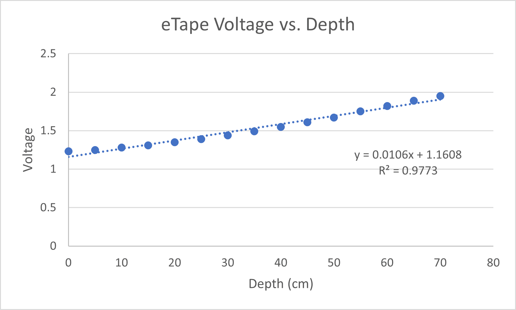
Hi everyone,
Just a quick update. The 100k voltage divider worked perfectly. My new voltage water level relationship is below.
Thanks again for your help @shicks.
James
<h2 class=”user-nicename”></h2>Attachments:
-
2021-03-24 at 1:42 PM #15316
Hi James,
If its the standard variable resistance then you should be able to just use the switched 3V. The ADS1115 is going to be more accurate.
FYI in case its of interest, I did some work with it and here is what I found out about the eTape; as I remember with the eTape, was that in calibration it wouldn’t register to the printed zero mark – and had an “actuation depth”, maybe it has changed. The general issue with an “elemental sensor” is that the raw sensing (in this case resistance) needs to be transformed into measurable units – in this case mm or inches, and for the eTape it is non-linear.
https://milonetech.com/products/standard-etape
They have linearizing modules, 0-5V and 4-20mA – though it requires a 6-24V stimulation
I did try the 4-20mA version, but burnt it out as it didn’t have reverse protection voltage in it.
Emails I sent, though maybe it has changed:
Subject: Configuring eTapes into a system?
Date: Thu, February 12, 2015 10:58 pmSome issues coming up
1) ‘0’ depth marking on the eTape scaling can never relate to a 0
electronic reading.
The data sheet says Actuation Depth a nominal 1″ – it seems that most of
the eTapes start recoding pressure change at about 0.2″
So where does the linearity start and to how to design to meet it?
2) For the simple eTape interface circuits, do you have any recommended
formuleas/manufacturing algorithims that translate measured Vout to a
linear depth reading that can apply to any eTape received.
<div class=”moz-cite-prefix”>On 2/19/2015 10:23 AM, chris.milone@milonetech.com wrote:</div><div>Hi Neil,</div>
<div></div>
<div>Sorry for the delayed response. Yes, a voltage divider output is a nonlinear function. We are working with another customer who has written some Arduino code that he claims automatically linearizes the output but we haven’t been able to get this to work as of yet.</div> -
2021-03-24 at 2:01 PM #15317
Another low cost depth sensor, showing the problems with using “raw sensing”, and the range is very small range 0-10cm and needs recalibrating evertime there is a power cycle. – https://www.vegetronix.com/Products/AquaPlumb/ – but my experiments have shown it has
My comment
“Works pretty nicely, except after power off.
Can’t take power off while in water – then reads 0.
Seems as a capacitance based sensor, when powering up needs to baseline the capacitance – guessing on my part – that is needs to be out of the water. Once read a baseline capacitance, then it detects increase in capacitance, water crossing. If the baseline capacitiance could be read, and then programmed, maybe it could survive a power off. “
-
-
AuthorPosts

- You must be logged in to reply to this topic.