
Home › Forums › Other Data Loggers › Arduino datalogger
- This topic has 40 replies, 5 voices, and was last updated 2020-02-15 at 4:21 AM by
agro0305.
-
AuthorPosts
-
-
2016-11-29 at 10:20 PM #1819
i am new to arduino, i am working on a project to use arduino to collect data from several SDI 12 sensors, for now i am trying to figure out how to view the results from the sensors on on my PC. tried using the SDI 12 library from https://github.com/EnviroDIY/Arduino-SDI-12 but can’t get it to show the results from the sensors. Please help
-
2016-11-29 at 10:57 PM #1820
Different types of SDI12 sensors have different commands for taking measurements and retrieving data from the sensor, so the Arduino code has to be modified for whatever specific sensor you’re using. Plus if you’re using multiple sensors, they each have to be pre-programmed with a unique address, which you then call separately in the Arduino code.
What type of sensors are you using? And did you modify any the example code provided with the SDI12 library?
-
2016-11-29 at 11:20 PM #1821
Hello Hicks thanks for the quick reply, I am using hydra probes and 5TM soil sensors. Please can you refer me to the sample code. Thanks
-
2016-11-30 at 12:26 PM #1825
Did you use the “Address Change” example included with the SDI12 library to give each sensor a unique address? Decagon 5TM sensors are always set to default address “0” when you first use them, so you’ll need to select new ones. I’d suggest something sequential like 1, 2, 3, etc so that it’s easy to cycle through them in the sampling code. How many sensors are you connecting at once? And are you using these with a Mayfly board or some other sort of hardware arrangement?
-
2016-12-01 at 2:37 PM #1829
I will try running the address change example, as for now i am trying to use a simple arduino board (arduino duemilanove). the main idea of my project is to use an arduino board to collect the data from an SDI-12 based sensor and then transmit it to another for storage. Do you think it will be possible to connect about 6 sensors to the arduino board and collect the data or an extra hardware is required to do that?
Thanks
-
2016-12-01 at 10:13 PM #1830
I’ve connected 15 of the Decagon 5TM sensors to one Mayfly board before, so it’s no problem to connect 6 to a Duemilanove. You’ll need to figure out how to get them all wired to the board, and that depends on what type of termination is on the ends of the sensors. Do your 5TM probes have the 3.5mm stereo headphone-type jack on the ends, or are they bare wires?
-
2016-12-01 at 10:28 PM #1831
Their endings are bare wires, please can you give me pointers on how to get this sensors working with the arduino, that is what sections of the code do i have to edit?
Thanks
-
2016-12-01 at 11:09 PM #1832
You’re going to need to connect the sensors one at a time to the Arduino board in order to program the address. Then you’ll need to hook them all together to the same bus. For example, all 6 of the sensor power wires need to go to the Vcc power bus, all 6 of the sensor ground wires need to go to the board GROUND, and all 6 of the sensor data lines need to go to a data pin (I like to use D7 for my SDI-12 data lines because it’s rarely used by other things like accessory shields).
So your challenge is going to be getting 3 sets of 6 wires all connected to just 3 pins on the Arduino board. This can be accomplished in a variety of ways, depending on how comfortable you are with soldering or stripping wires or making a custom board with some screw terminals. Or you might be able to do it with a breadboard if you don’t mind cramming the sensor wires into the holes (it’s generally bad practice to cram medium-gage bare wires into a solderless breadboard because it permanently widens the contacts making it unreliable for later use with smaller components).
Do you have a breadboard, or some spare screw terminals, or a screw-terminal breakout shield for the Duemilanove? Or maybe you just want to use a wire nut to join each of the 6 wires together along with one wire to connect to Arduino board? It’s usually not recommended to join that many wires with one wire nut, but it might be possible if you do it just right. Is this just for a temporary test/experiment, or are you thinking of a long term setup?
Once we figure out the wiring, I can post the sample code for cycling through 6 channels. How often do you want to take a sample, and is it just being displayed on the computer using the Arduino IDE’s serial monitor? If you used a Mayfly the data could also be time-stamped and stored on the memory card.
-
2016-12-01 at 11:31 PM #1833
Hello Hicks,
Thanks for the quick reply, for now i will use a wire nut to join the sensor wires, and i will want to get the samples every 10 minutes. Right now if i can get the results on the serial monitor that will be ok because its just for testing, but latter on i plan on transmitting this data wirelessly to be stored on another arduino, probably the Mayfly.Thanks
-
2016-12-02 at 1:54 AM #1834
Here’s some sample code for running 6 Decagon 5TM probes with a standard Uno board. It could be modified by changing the pin number for the LED, in the example below I used the default pin 13 for the onboard LED. Mayfly users would want to select either 8 or 9. I usually prefer to do long-time recording with a separate real-time-clock module like what’s on the Mayfly, but in this example I just polled the rolling “millis” counter to get the time since the board was started. I set the example interval to 60 seconds, but you could adjust that if you wanted.
Remember that first you have to connect each 5TM sensor to the Arduino board one at a time and configure each one with a unique channel number. To work with the code below, you should number them sequentially from 1 to 6. Use the “address change” example that’s included with the SDI12 library, making sure to hook the sensor data pin to the correct pin that’s stated in the example, or change the example to match your wiring. In my example code below, I put the sensor data pin on D7.
I think this code should work, it compiles properly, I just don’t have 6 sensors handy to test it completely. It’s based on some thoroughly-tested Mayfly code, but I just removed all of the code regarding the Mayfly’s RTC, memory card, and sleeping functions.
Arduino12345678910111213141516171819202122232425262728293031323334353637383940414243444546474849505152535455565758596061626364656667686970717273747576777879#include <SDI12.h>#define DATAPIN 7 // change to the proper pin for sdi-12 data pin, I prefer D7SDI12 mySDI12(DATAPIN);unsigned long previousMillis = 0;const long interval = 60000; //set the interval (in milliseconds). ex: 60000 = 60 secondsvoid setup (){pinMode(13, OUTPUT);digitalWrite(13, LOW); //turn off the onboard LED to start withSerial.begin(57600);mySDI12.begin();Serial.println("Sketch for sampling multiple SDI12 sensors");delay(1000);}void loop (){unsigned long currentMillis = millis();if(currentMillis - previousMillis >= interval || previousMillis == 0) {previousMillis = currentMillis;digitalWrite(13, HIGH); //turn on the onboard LED to show that samples are being takenSerial.print("Time: ");Serial.print(currentMillis/1000); //print out the current time, in secondsSerial.print(" ---- ");for (char j = '1'; j <= '6'; j++) { //go through channels 1 to 6tmMeasurement(j);}Serial.println();digitalWrite(13, LOW); //turn off the LED to show that samples are done}delay(1000);}void tmMeasurement(char c){ //5TM soil moisture sensorString command = "";float Ea = 0.0;float temp = 0.0;float VWC = 0.0;command += c;command += "M!"; // SDI-12 measurement command format [address]['M'][!]mySDI12.sendCommand(command);delay(500); // wait a secmySDI12.flush();command = "";command += c;command += "D0!"; // SDI-12 command to get data [address][D][dataOption][!]mySDI12.sendCommand(command);delay(500);if(mySDI12.available() > 0){int channel = mySDI12.parseInt();Ea = mySDI12.parseFloat();temp = mySDI12.parseFloat();VWC = (4.3e-6*(Ea*Ea*Ea)) - (5.5e-4*(Ea*Ea)) + (2.92e-2 * Ea) - 5.3e-2 ; //the TOPP equation used to calculate VWCSerial.print("Sensor:");Serial.print(channel);Serial.print(": Ea=");Serial.print(Ea);Serial.print(", VWC=");Serial.print(VWC);Serial.print("%, Temp=");Serial.print(temp);Serial.print("degC .... ");}mySDI12.flush();} -
2016-12-04 at 2:29 PM #1839
Thanks for the reply. I tried following the steps as you suggested above, i noticed when i uploaded the address change example onto the arduino board and connected the sensors it ask for new address i input 1 for the first sensor but the address of the sensor still said 0. I continued with the other sensors as you had suggested, but at the end when i ran the sample code you sent i could not get the results. I don’t know exactly what i am doing wrong.
So i went ahead to measure the input voltage at the sensors but noticed it was really low so i am guessing thats where the issue is. Please can you provide me with a diagram on how to connect the few sensors to gather?Thanks
-
2016-12-08 at 11:56 AM #1852
The sample code above will not work properly until you’ve correctly changed the channel number for each of the 6 sensors. Also, once you do that and you have a different number of sensors other than 6, you’ll need to change the number in line 31 to the correct number of sensors.
So first you should make sure you change the channel number of one sensor at a time and then verify that the sample code for reading one sensor works properly before proceeding further.
To connect a Decagon 5TM probe to your Arduino board, connect the sensor bare braided wire to a ground pin of the Arduino. Connect the white sensor wire to 5V, and connect the red sensor wire to the data pin (pin D7 in the example above).
-
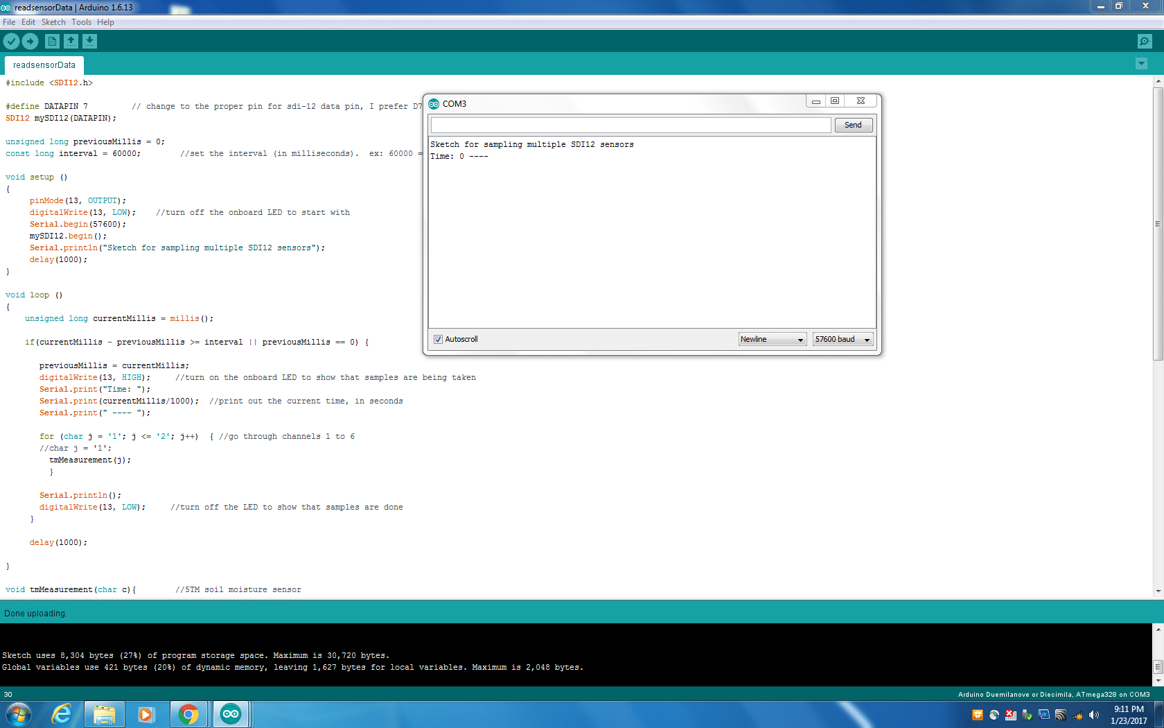
2017-01-23 at 11:20 PM #1939
Hello Hicks, tried the code you provided for 2 sensors, and followed the steps but still cant get results on the serial monitor, can you please check the code to see if you can get the results.
Thanks
Attachments:
-
2017-01-24 at 6:19 AM #1941
The code I posted above has been running for years on several different loggers, so it is correct. Have you verified that you correctly wired the signal, power, and ground lines of the sensors to your Arduino board. If you’re using a Mayfly and one of the Grove ports, you’ll need to turn on the switched external power for the grove port (D22), or you can just connect them to your board’s Vcc pin. Keep in mind that with the Decagon sensors, the red wire is the data wire and white is the positive power wire. Once you’ve assured the sensor is connected properly you need to make sure you successfully programmed each of your 6 sensors with a unique SDI12 addresss using the “Address Change” example included with the SDI12 library. Do them one at a time and verify that you’re getting output from each one (one at a time) on the serial monitor. Once you’ve done all that, then you can put all 6 sensors on the board and run the sketch I posted above. If you want to use less than 6 sensors, just change the ‘6’ in line 31 to whatever the max number of sensors are. You can even put ‘1’ if you want to run the sketch with just 1 sensor.
If that still doesn’t work, maybe you could post some photos if your setup and the wiring so we can see if everything is connected properly.
-
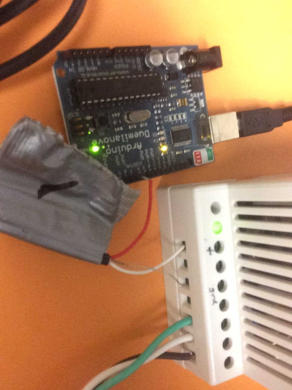
2017-01-24 at 10:16 PM #1946
Tried the code again and followed the steps as mentioned above, but can’t still get data from the sensor on the Arduino serial monitor. attached is the section of the code I edited to work just for a single sensor and the connection of the sensor to the board. Please help with what I am doing wrong.
Attachments:
-
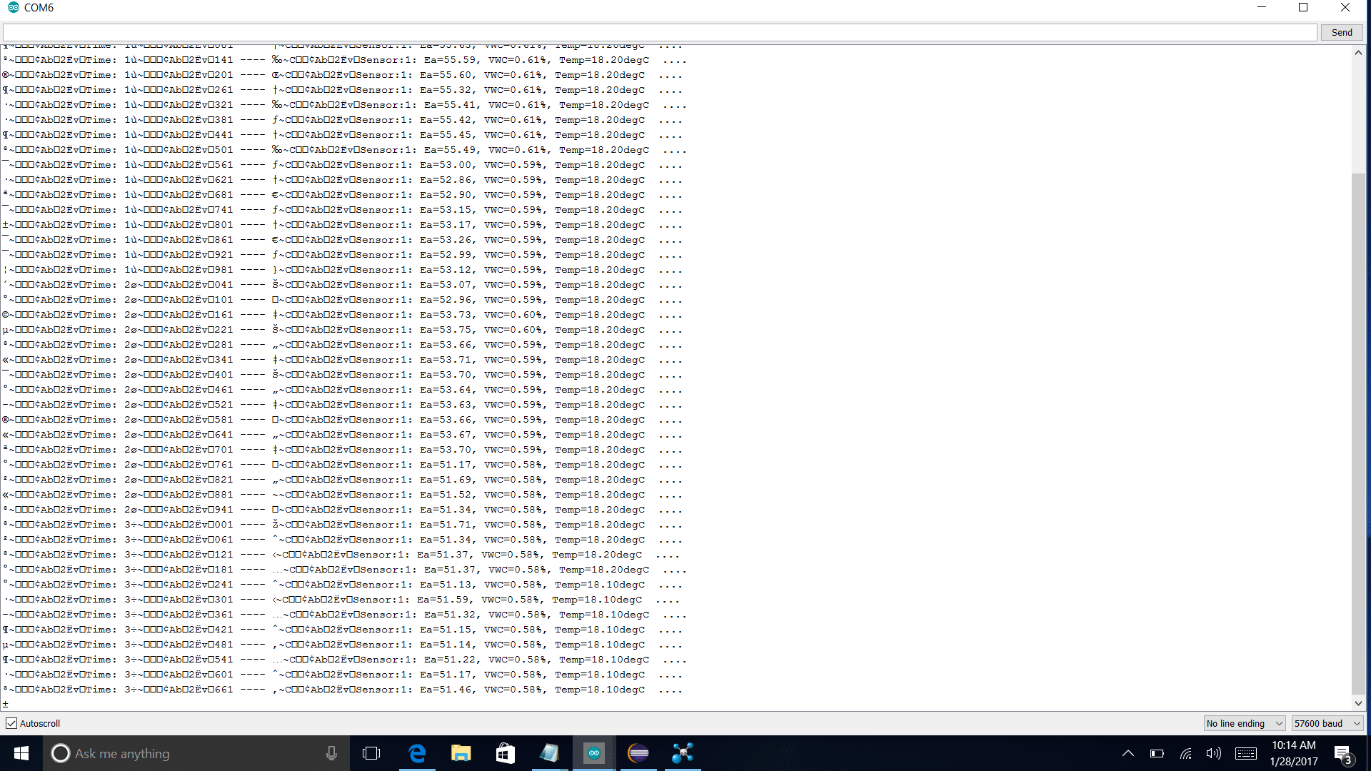
-
2017-01-25 at 12:27 AM #1949
I don’t know what the white box is in the top right of that one photo, but I’m assuming it’s an external power supply. I’m not sure why you are using that; the sensor definitely doesn’t need it and all 3 sensor wires are supposed to be connected directly to the Arduino board. As stated in several of my replies above, connect the sensor red wire to D7. Connect the sensor white wire to the ARDUINO’s 5V pin (also sometimes called Vcc). And connect the sensor bare wire to the ARDUINO’s ground pin. You don’t need an external power supply for any of this. You’re not getting any data because the Arduino board and external supply don’t share a common ground, so there’s no common reference between them so the Arduino is unable to measure anything on that red data wire because it’s all by itself as far as the Arduino can tell. What voltage were you putting on the white wire connected to the + terminal of that external supply?
Remove the supply completely and connect the sensor directly to Arduino board. Run the “simple_logger” example that’s included with the SDI12 library (changing the DATAPIN in line #37 from pin 9 to pin 7 if you want it to match the code above…). It’ll scan all of the channels and tell you if it sees a sensor and prints what channel it’s on and some basic info about it. If it’s not set to channel 1 or isn’t reading it at all, then you’ll need to keep troubleshooting before trying the code above. You can also use the “wildcard” example for just testing the sensor. Use the “address_change” example if you want to change the sensor address. You should be able to see if it’s all working correctly there too. If all of that looks good, then you can try the above code again, and making sure that you’re using the proper data pin in the DATAPIN declaration line each time. My example above is pin 7, but the library’s have a default of 9. Either one is fine, just be consistent and make sure you’ve got it hooked up right.
-
2017-01-25 at 12:45 AM #1950
Thanks for the reply, the reason I used an external power supply is because when I connected the sensor wires to the Arduino board, and ran the address change example the sensor couldn’t be found by the code so the code continued searching for a sensor in a continues loop. Let me try every step you have recommended and hopefully I get some data from the sensor.
Thanks
-
2017-01-25 at 1:04 AM #1951
What voltage were you putting on that white wire with the external supply?
If you use the “address_change” example, the sensor red wire needs to go on D9 if you want to run the code as-is. If you hook the sensor up as I described and run the address_change example and still don’t get anything, post a new photo of that setup. If you have a different Arduino or sensor, you might also try using one of those in case you damaged either the sensor or the Arduino with too high of an external voltage on the sensor excitation wire.
-
2017-01-25 at 1:17 AM #1952
Thanks, I followed all the steps above and connected the sensor to the Arduino and all works great. I can get data from the sensor now. Just a quick question if I want to connect several sensors to the Arduino will the 5V be enough or I will have to use an external power supply making sure both the supply and Arduino have the same ground?.
Thank you so much for the help.
-
-
2017-01-25 at 1:48 AM #1953
No, you’ll never need an external supply even if you’re using dozens of 5TM soil moisture sensors. The reason is that the code I posted above will only power one sensor at a time. All of the other sensors are basically sleeping and using virtually no power until they are “woken up” one at a time by the call to their SDI12 address. One 5TM sensor only draws 10mA during measurement, which is only for a fraction of a second. So with all of the sensors connected to the 5V pin of the Arduino and essentially sleeping until they’re called individually for that fraction of a second, you’ll never run the risk of drawing too much current.
Now, if you switch to a different type of sensor, that is something to be cautious about, but it’s not a problem for the 5TM. And yes, connecting the external supply’s ground to the Arduino ground could allow you to power the sensors with the external supply, but it’s totally unnecessary in this case.
The hardest thing about hooking up multiple sensors to one Arduino is connecting all of the wires to one pin. In you case, 6 red sensor wires need to get connected to the digital signal pin, 6 white wires get connected to 5V, and 6 bare wires go to ground. You’ll either have to get creative with a protoboard or breadboard or wirenuts or something similar.
-
2017-01-25 at 1:57 AM #1954
I plan on making this project interesting that way I get a better understand on how to work with the Arduino and the SDI12 sensors. I am thinking of wireless transfer of the data using ZigBee, then adding memory card shields on the Arduino to store the collected data locally. So do you have any pointers that could help me achieve these extra features. Thanks
-
2017-01-25 at 10:31 AM #1955
If you’re trying to use a Zigbee module and a microSD card with an Arduino board, you could buy a bee adapter shield and a memory card shield and stack them all together. If you’re logging data over time, you’ll also want a real-time-clock module to be able to timestamp the data on the memory card. But instead of trying to get 4 separate boards to work together, that’s why we created the Mayfly board. It has the Bee socket, memory card socket, real time clock, and several other handy features that make it super simple to do everything you’re looking for all with one board.
-
2017-01-25 at 12:04 PM #1958
I tried placing an order for the mayfly board on amazone but it looks like they are not available and it says they don’t know when next the board will be available for ordering. Do you have any idea where i could buy the board?
Thanks -
2017-01-27 at 9:38 AM #1966
-
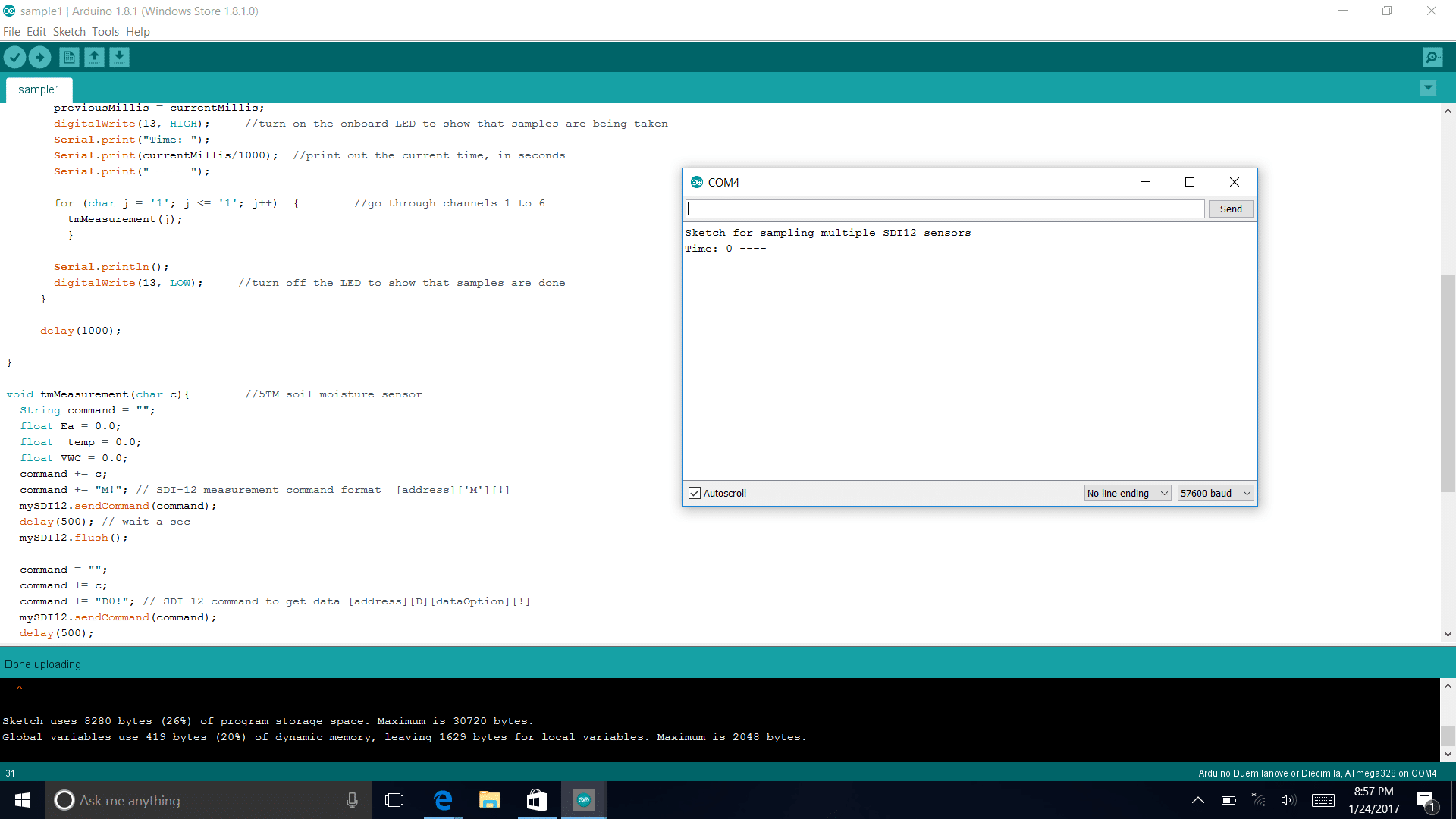
2017-01-28 at 11:23 AM #1968
Hello Shannon,
I implemented the wireless communications using Xbee S2, I do get the data from the sensors using your code but the serial mornitor gives some extra junk data as shown in the attached screen short. I am trying to figure out how to eliminate that, Can you please help.
Thanks
Attachments:
-
-
-
2017-01-29 at 10:06 PM #1975
Do you only get that “extra junk” (as you described it) on the serial monitor when the Xbee is attached? It looks to me like you’ve got the Xbee radio on the same serial port as the board communication (the Arduino’s hardware serial port, which is pins 0 and 1), right? The Arduino board is talking to the PC at 57600 baud, but the Xbee has a default speed of 9600. So unless you changed that by programming the Xbee separately (using either the X-CTU program or a terminal and AT commands) then you’re going to get a mis-match between the 2 devices. But more importantly, you can’t have the Xbee on the same hardware serial port as the computer. That’s why I like the Mayfly, it has 2 hardware serial ports. The Mayfly talks to the PC serial monitor on the first one, and the Mayfly talks to the Xbee module on the second one.
If you’re using an Arduino Mega board (it has 3 hardware serial ports) or some of the other newer Arduino boards or derivatives, they sometimes have 2 hardware serial ports. But if you’re using the Uno, then you’ve got to implement a separate software serial port for the processor to talk to the Xbee module so that you can still print stuff to the screen. Otherwise, your Xbee module is going to try to transmit everything that you sketch is printing to the serial monitor and you’ll see random stuff on the serial monitor that’s coming from and going to the Xbee.
If you’re not familiar with Xbee’s and using software serial ports, you’ll need to find some examples of how to set that up.
-
2017-01-30 at 12:35 AM #1976
I am using the Arduino Fio, because it has Xbee slots already available on the board. As of the board rate when programming the Xbee I set them to 57600. So I think that’s not the problem. I am trying to see how many hardware serial ports Fio has. I will think they should have more than 1 port for the transmission since they already support xbee modules on the board. Do you think I meight have an issue with the programming of the xbee?
Thanks
-
2017-01-30 at 12:47 PM #1977
If you’re using the Fio board, then your Xbee is forced to use the only hardware serial port on the board (pins 0 and 1). So if you really want to print out data to the serial port at the same time, you’ll need to use 2 other pins for that, using SoftwareSerial. I assume you’re using a FTDI adapter for connecting your Fio to your computer since the Fio doesn’t have built-in USB support. So just use some wire jumpers to connect the RX and TX pins of your FTDI adapter to 2 unused pins on your Fio and designate them as the SoftwareSerial pair in your sketch. So anything you want to send via the Xbee goes to the serial port, and anything you want to print on the computer’s serial monitor goes to the SoftwareSerial port.
But if you haven’t configured your Xbee using X-CTU or through at commands, then your Fio can’t communicate with the Xbee at 57600 baud so don’t use that speed in your sketch. You’ll have to either change the Fio sketch to 9600 or change the Xbee to 57600. Where are you transmitting your Xbee data to? I assume you have a pair of them and will use the other one as a receiver somewhere? Keep in mind that the baud rate that you configure for the Xbee’s UART communication is totally separate from the actual transmit rate of the modules. You’re only changing the speed at which the Xbee communicates with external UART devices. It doesn’t matter what speed you select, as long as the radio and the device are both using the same one.
-
2017-01-31 at 1:43 AM #1979
I am transmitting the data to another xbee connected to my computer with the help of the xbee explorer and its setup as coordinator. I tried using the softwareSerial library and connecting the Tx and Rx ports to pins 10 and 11, but the results did not get better. Please let me know if you have any other idea.
-
2017-01-31 at 8:05 AM #1980
Past your code into this thread and I’ll take a look at it. Also, did you change the baud rate of the Xbee modules using X-CTU, or are they still set to the default?
Also, if you’re ever having trouble with a new sketch because you’re testing several new sections together for the first time, try removing some of them to simplify it and make sure each small block works separately before trying all of them together.
For example, remove all the SDI-12 stuff and the Xbee and the software serial and just make sure you can successfully get the FIO to say “Hello World” on the serial monitor port at 9600. Then use that same sketch but unplug the USB cable and put the Xbee module on the FIO. Use a separate battery (so you don’t get conflicts from the USB port) and verify that you see “Hello World” on your other Xbee coordinator receiver monitor. If you’re able to do that, then go back to the sketch and add the software serial on 2 unused pins and monitor that with your PC serial monitor. Verify that you see the same thing on the PC that you see on your Xbee coordinator. If all of that works, then you can add back the code for the SDI12 sensor.
Another thing to note is that you’re probably going to get an error when compiling the code if you’re using SoftwareSerial and SDI12 at the same time due to port interrupt conflicts. That’s why I created the SDI12_Mod and SoftwareSerialMod libraries that are found in our Github repo so that you can use those 2 libraries together without conflicts.
-
2017-01-31 at 10:01 PM #1993
Bellow is a sample sketch I am trying to run to make sure I get the software serial going but still it doesn’t work.
#include <SoftwareSerial.h>
SoftwareSerial mySerial(10, 11); // RX, TX
void setup() {
// Open serial communications and wait for port to open:
Serial.begin(57600);
while (!Serial) {
; // wait for serial port to connect. Needed for native USB port only
}Serial.println(“Goodnight moon!”);
// set the data rate for the SoftwareSerial port
mySerial.begin(4800);
mySerial.println(“Hello, world?”);
}void loop() { // run over and over
if (mySerial.available()) {
Serial.write(mySerial.read());
}
if (Serial.available()) {
mySerial.write(Serial.read());
}
} -
2017-02-01 at 11:49 AM #1995
I’m going to need more information if you want me to diagnose your problem. When you say “it doesn’t work”, do you mean that it doesn’t compile, or there’s no output on the serial monitor, or is there nothing transmitted by the Xbee?
Also, please answer these questions:
What type of USB-to-TTL adapter are you using to program the Fio?
How is it connected to the Fio?
How did you configure the Xbee radios? What settings did you change from their default values on the Xbees?
If one Xbee is in the Fio, where is your second Xbee and how are you viewing the received data? -
2017-02-02 at 10:30 PM #2001
What I mean by “its not working” is, I still have some extra characters on the Arduino serial monitor when the message “goodnight moon” is printed.
I am using an FTDI cable 5V VCC-3.3V I/O to program the Arduino Fio.
During the programming I make sure the Xbee is not on the Fio board.
For the configuration of the Xbee modules I used the XCTU software changing the baud rate of both xbees to 57600.
The second xbee is connected to the PC with the help of xbee explorer from sparkfun and its set to coordinator mode.What I really want to try is print a message from the Arduino to the Arduino serial monitor without any extra characters using the Xbee modules installed.
Thanks
-
2017-02-03 at 12:13 AM #2002
Try this: use X-CTU to reprogram both of the Xbee modules to 9600 baud and then change the baud rate in your Fio sketch to 9600 for the serial port and also 9600 for the software serial port (it’s easier and less confusing if everything uses the same rate). I’ve had trouble in the past with some of my Xbee units printing garbled text to the Arduino board at higher baud rates, so perhaps that’s where your mystery characters are coming from.
-
2017-02-07 at 10:31 PM #2012
i tied changing the baud rate as you suggested, but unfortunately i see the characters when i print use the arduino software serial monitor. when i use the X-ctu console i don’t have the characters.
Wondering do you have any specific arduino boards you will recommend for use in outdoor experiments?
Thanks
-
2017-03-14 at 4:08 AM #2081
So i have decided to improve my project by adding a data logger shield from adafruit. can seam to get the data from the attached decagon 5TM sensors. Please can any one help with what i am doing wrong in my sketch.
#include <SPI.h>
#include <SD.h>
#include <Wire.h>
#include “RTClib.h”
#include <SDI12.h>// A simple data logger for the Arduino digital pins
// how many milliseconds between grabbing data and logging it. 1000 ms is once a second
#define LOG_INTERVAL 60000 // mills between entries (reduce to take more/faster data)// how many milliseconds before writing the logged data permanently to disk
// set it to the LOG_INTERVAL to write each time (safest)
// set it to 10*LOG_INTERVAL to write all data every 10 datareads, you could lose up to
// the last 10 reads if power is lost but it uses less power and is much faster!
#define SYNC_INTERVAL 60000 // mills between calls to flush() – to write data to the card
uint32_t syncTime = 0; // time of last sync()#define ECHO_TO_SERIAL 1 // echo data to serial port
#define WAIT_TO_START 0 // Wait for serial input in setup()// the digital pins that connect to the LEDs
#define redLEDpin 2
#define greenLEDpin 3#define DATAPIN 7 // change to the proper pin for sdi-12 data pin, I prefer D7
SDI12 mySDI12(DATAPIN);// The analog pins that connect to the sensors
//#define photocellPin 0 // analog 0
//#define tempPin 1 // analog 1
//#define BANDGAPREF 14 // special indicator that we want to measure the bandgap//#define aref_voltage 3.3 // we tie 3.3V to ARef and measure it with a multimeter!
//#define bandgap_voltage 1.1 // this is not super guaranteed but its not -too- offRTC_PCF8523 RTC; // define the Real Time Clock object
// for the data logging shield, we use digital pin 10 for the SD cs line
const int chipSelect = 10;// the logging file
File logfile;
void tmMeasurement(char c);void error(char *str)
{
Serial.print(“error: “);
Serial.println(str);// red LED indicates error
digitalWrite(redLEDpin, HIGH);while(1);
}void setup(void)
{
Serial.begin(9600);
Serial.println();// use debugging LEDs
pinMode(redLEDpin, OUTPUT);
pinMode(greenLEDpin, OUTPUT);#if WAIT_TO_START
Serial.println(“Type any character to start”);
while (!Serial.available());
#endif //WAIT_TO_START// initialize the SD card
Serial.print(“Initializing SD card…”);
// make sure that the default chip select pin is set to
// output, even if you don’t use it:
pinMode(10, OUTPUT);// see if the card is present and can be initialized:
if (!SD.begin(chipSelect)) {
error(“Card failed, or not present”);
}
Serial.println(“card initialized.”);// create a new file
char filename[] = “LOGGER00.CSV”;
for (uint8_t i = 0; i < 100; i++) {
filename[6] = i/10 + ‘0’;
filename[7] = i%10 + ‘0’;
if (! SD.exists(filename)) {
// only open a new file if it doesn’t exist
logfile = SD.open(filename, FILE_WRITE);
break; // leave the loop!
}
}if (! logfile) {
error(“couldnt create file”);
}Serial.print(“Logging to: “);
Serial.println(filename);// connect to RTC
Wire.begin();
if (!RTC.begin()) {
logfile.println(“RTC failed”);
#if ECHO_TO_SERIAL
Serial.println(“RTC failed”);
#endif //ECHO_TO_SERIAL
}logfile.println(“millis,stamp,datetime,sensor,ea,vwc,temp “);
#if ECHO_TO_SERIAL
Serial.println(“Sketch for sampling multiple SDI12 sensors”);
Serial.println(“millis,stamp,datetime,sensor,ea,temp”);#endif //ECHO_TO_SERIAL
Serial.println();
// If you want to set the aref to something other than 5v
//analogReference(EXTERNAL);
delay(1000);
}void loop(void)
{//Now lets look at the timestamp
DateTime now;// delay for the amount of time we want between readings
delay((LOG_INTERVAL -1) – (millis() % LOG_INTERVAL));digitalWrite(greenLEDpin, HIGH);
// log milliseconds since starting
uint32_t m = millis();
logfile.print(m); // milliseconds since start
logfile.print(“, “);
#if ECHO_TO_SERIAL
Serial.print(m); // milliseconds since start
Serial.print(“, “);
#endif// fetch the time
now = RTC.now();
// log time
logfile.print(now.unixtime()); // seconds since 1/1/1970
logfile.print(“, “);
logfile.print(‘”‘);
logfile.print(now.year(), DEC);
logfile.print(“/”);
logfile.print(now.month(), DEC);
logfile.print(“/”);
logfile.print(now.day(), DEC);
logfile.print(” “);
logfile.print(now.hour(), DEC);
logfile.print(“:”);
logfile.print(now.minute(), DEC);
logfile.print(“:”);
logfile.print(now.second(), DEC);
logfile.print(‘”‘);
#if ECHO_TO_SERIAL
Serial.print(now.unixtime()); // seconds since 1/1/1970
Serial.print(“, “);
Serial.print(‘”‘);
Serial.print(now.year(), DEC);
Serial.print(“/”);
Serial.print(now.month(), DEC);
Serial.print(“/”);
Serial.print(now.day(), DEC);
Serial.print(” “);
Serial.print(now.hour(), DEC);
Serial.print(“:”);
Serial.print(now.minute(), DEC);
Serial.print(“:”);
Serial.print(now.second(), DEC);
Serial.print(‘”‘);
#endif //ECHO_TO_SERIAL
//for(char j=’1′;j<=’3’;j++){
tmMeasurement(j);
//}
Serial.println();
}
//delay(1000);
// Now lets look at collecting the data from the sensorsvoid tmMeasurement(char c){
String command = “”;
float Ea = 0.0;
float temp = 0.0;
float VWC = 0.0;
command += c;
command += “M!”; // SDI-12 measurement command format [address][‘M’][!]
mySDI12.sendCommand(command);
delay(500); // wait a sec
mySDI12.flush();command = “”;
command += c;
command += “D0!”; // SDI-12 command to get data [address][D][dataOption][!]
mySDI12.sendCommand(command);
delay(500);if(mySDI12.available() > 0){
int channel = mySDI12.parseInt();
Ea = mySDI12.parseFloat();
temp = mySDI12.parseFloat();VWC = (4.3e-6*(Ea*Ea*Ea)) – (5.5e-4*(Ea*Ea)) + (2.92e-2 * Ea) – 5.3e-2 ; //the TOPP equation used to calculate VWC
logfile.print(“, “);
logfile.print(channel);
logfile.print(“, “);
logfile.print(Ea);
logfile.print(“, “);
logfile.print(VWC);
logfile.print(“, “);
logfile.print(temp);#if ECHO_TO_SERIAL
Serial.print(“, “);
Serial.print(channel);
Serial.print(“, “);
Serial.print(Ea);
Serial.print(“, “);
Serial.print(VWC);
Serial.print(“, “);
Serial.print(temp);#endif //ECHO_TO_SERIAL
/*/analogRead(photocellPin);
//delay(10);
//int photocellReading = analogRead(photocellPin);//analogRead(tempPin);
//delay(10);
int tempReading = analogRead(tempPin);// converting that reading to voltage, for 3.3v arduino use 3.3, for 5.0, use 5.0
float voltage = tempReading * aref_voltage / 1024;
float temperatureC = (voltage – 0.5) * 100 ;
float temperatureF = (temperatureC * 9 / 5) + 32;logfile.print(“, “);
logfile.print(photocellReading);
logfile.print(“, “);
logfile.print(temperatureF);
#if ECHO_TO_SERIAL
Serial.print(“, “);
Serial.print(photocellReading);
Serial.print(“, “);
Serial.print(temperatureF);
#endif //ECHO_TO_SERIAL
*//*
// Log the estimated ‘VCC’ voltage by measuring the internal 1.1v ref
analogRead(BANDGAPREF);
delay(10);
int refReading = analogRead(BANDGAPREF);
float supplyvoltage = (bandgap_voltage * 1024) / refReading;logfile.print(“, “);
logfile.print(supplyvoltage);
#if ECHO_TO_SERIAL
Serial.print(“, “);
Serial.print(supplyvoltage);
#endif // ECHO_TO_SERIALlogfile.println();
#if ECHO_TO_SERIAL
Serial.println();
#endif // ECHO_TO_SERIAL
*/
digitalWrite(greenLEDpin, LOW);// Now we write data to disk! Don’t sync too often – requires 2048 bytes of I/O to SD card
// which uses a bunch of power and takes time
if ((millis() – syncTime) < SYNC_INTERVAL) return;
syncTime = millis();// blink LED to show we are syncing data to the card & updating FAT!
digitalWrite(redLEDpin, HIGH);
digitalWrite(redLEDpin, LOW);
}
logfile.flush();}
-
2019-02-23 at 11:31 PM #12817
This is great thank you!
-
2020-02-14 at 7:36 PM #13818
Can You send code for conecting multiple sensors on same bus, eg pin.
-
2020-02-14 at 9:12 PM #13819
The code and wiring depends on what kind of sensors you’re talking about connecting to the same pin. Are you using sensors with SDI-12 or modbus communication? Are these sensors already included in the many supported sensors in the EnviroDIY ModularSensors library, or are they unique sensors we haven’t used before?
-
-
2020-02-15 at 4:20 AM #13820
We are trying to connect SDI-12 sensors., not modbus. Sensors which we try to connect are EnviroPro EP100G. They are measuring Temperature, soil moisture and Ec. They are 40 cm long and on each 10 cm they have sensors for those three measurement. There are two sensors connected to bus, eg data pin. With script which I send it to You it is working, measuring but this is only for one sensor. Sensors have unique address 1 and 2 . We know how to change address of sensor. When we put before command C, C1, C2 or C3, question mark ?, it does not measure anything. When we change in file sensor address from 2 to 1, it works again reading from sensor with address 1. In another reply I will send You file with EnviroPro SDI-12 commands. We connect them in variant supplying sensor with 5V from Arduino 2560 and supplying sensor with 12V from separate power supply.In variant with 12V, power supply is 2A, so issue with current is not a problem. It is only working with this example, which I attach. When we load and compile in Arduino 2560 Your examples for SDI-12, it does not work, eg dont measure anything. We try with other pins as well, eg pin 2 and 3, no measurement. It is same situation with some other examples which we find on net for SDI-12. They dont work. We want to use Your MyFly data logger in our project, but we want to be sure, that we can measure. Please help with some code or explanation, what we are doing wrong. Please help with some code or advice.
Attachments:
-
2020-02-15 at 4:21 AM #13822
Enviro PRO SDI-12 command, as promies in previous repply.
Attachments:
-
-
AuthorPosts

- You must be logged in to reply to this topic.