Home › Forums › Mayfly Data Logger › Mayfly v1.1 technical questions forum thread › Reply To: Mayfly v1.1 technical questions forum thread
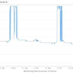
You can actually get useful information from this plot like that because it shows you what days were sunny and what days were cloudy, which could help you understand why the underlying raw battery voltage might increase or decrease over time. For example, in the plot below you can see it was completely sunny on September 9, mostly sunny on Sept 10, totally cloudy on Sept 11 (no charging at all), and mostly sunny on the 12th and 13th. Every station is going to have a different charging pattern based on tree canopy, time of year, weather, obstacles, etc, but having the graph showing the input voltage to the Mayfly can be very useful for monitoring the overall status of a station. Also, if a Mayfly is being powered directly through its USB port (with or without a Lipo also connected to the Lipo socket), then the voltage measured by the analog A6 input will show 4.95v.
If you would rather monitor the raw Lipo battery voltage and not see the swings of the solar panel (or USB) input, then you can follow the directions mentioned below, which come from the Mayfly Jumper Settings page.
SJ27: Analog pin A6 connected to either combination Voltage in (default) or direct Lipo battery socket. The default setting works best so that the Mayfly can sense the input voltage of whichever source is highest. With just a Lipo connected, A6 will see the battery voltage (~3.7v). If a solar panel is connected, then A6 will see approximately 4.2v during full sun. If a USB cable is connected, A6 will see 4.9v. If you want to see only the raw Lipo battery voltage independent of the higher voltage from the solar panel, change the solder jumper to Lipo.

 Welcome to EnviroDIY, a community for do-it-yourself environmental science and monitoring. EnviroDIY is part of