@kyoung18
Active 9 years, 1 month agoForum Replies Created
-
AuthorPosts
-
Hi all,
Just wanted to update here with our results. We deployed our datalogging device in the NE Branch of the Anacostia River right next to USGS Site # 01649500 (http://waterdata.usgs.gov/usa/nwis/uv?site_no=01649500). We deployed here mainly so that we had an easy way to verify the accuracy of our sensors by comparing it to USGS’s data. We built the device for $275 + $6/month for cellular data. Our first deployment we were unable to get the stalker to sleep (not immediately sure why), so we just put a 15-minute delay in between sensor readings. The device lasted for 47 hours before running out of battery. You can see the data we collected at https://evh.herokuapp.com/devices/2. More info on the device itself can be found at: https://hackaday.io/project/8807-envirohub. We also wrote custom software for collecting and viewing the readings (which can be found here: https://github.com/kwyoung11/WaterLog).
If you compare our data to the USGS data for the site mentioned, you can see that our data is considerably off, although it looks like the trends in the data for the parameters collected are roughly similar. So next steps would include calibrating the accuracy of the sensors. We also accidentally fried the turbidity sensor we had because we were looking at the wrong data sheet, so that will hopefully be included in the next iteration. I am also planning on designing a custom enclosure for the device using tinkercad.com and 3D printing it. We ended up changing our design considerably from the sketch I posted and instead went with a floating water-proof box (using 4 small buoys). More pictures of this are in the hackaday link. However, this design is untested during high flows and its likely more visible and as such perhaps more susceptible to vandalism.
Thanks for sharing Neil, thats pretty interesting. We are developing a similar project in my university class — server software for collecting data from environmental sensors either via wireless http or SD card, with a front-end interface with map and graph displays and integration of other data sources (weather, USGS water service). We are also developing the hardware device measuring water quality, will update here when we deploy/install it and report on findings.
Thanks for the information everyone.
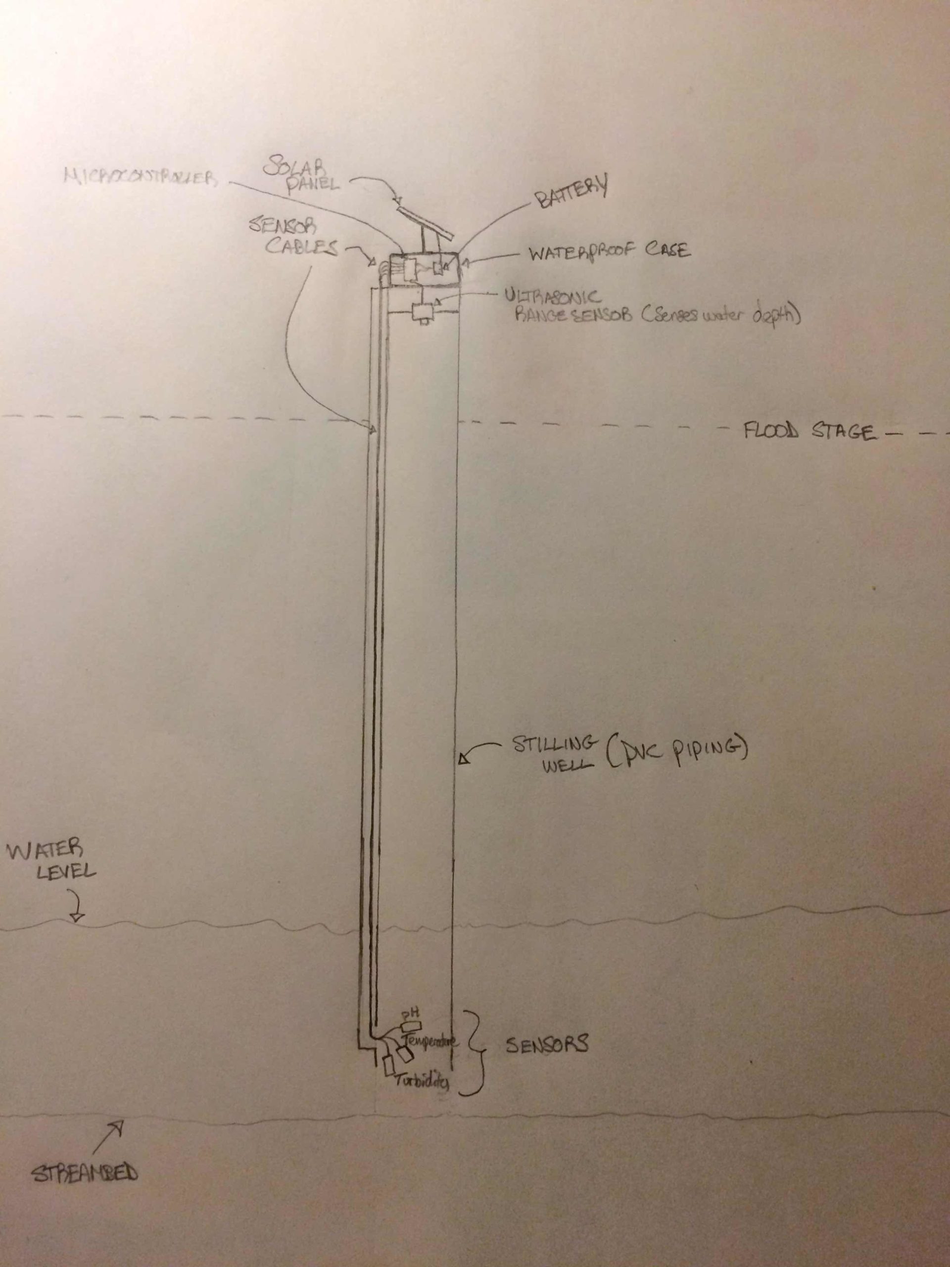
I drew a diagram of the physical construction of the water quality system as I have envisioned it, which I’ve attached below. I wanted to ask your thoughts about the design, particularly any apparent flaws you might see. Do you think there will be sediment buildup inside the stilling well? Is the sensor placement appropriate? Other points I am missing?
I would expect this to be installed in the middle of a stream using rebar or a fence post (dug into the streambed) OR have it be affixed somehow to a bridge structure along the stream/river. The diagram is attached below.
Any information/tips would be much appreciated.
Attachments:
Hi Dave, Rene, Neil,
Thank you very much for sharing your information, it is a great help.
Dave, that is a good point in regards to sediment build up if one were to enclose the sensors as I had initially described. PVC piping to enclose sensors/sensor housing is a good idea. My initial thoughts would be to have the waterproof-encased data logging equipment secured on the streambank, with PVC-enclosed sensor housing running along the streambed, secured with rebar or similar. I would think you would want the sensors perpendicular to the streambed, so the end of the PVC piping would look like an upside-down U to properly position the sensors relative to the stream.
Rene, the Seeeduino Stalker looks quite promising and simpler to set up than an Arduino Board, due to the integrated solar charging circuit. I also found the GPRSBee (GSM expansion board) which is compatible with the Seeeduino Stalker at http://www.seeedstudio.com/depot/GPRSbee-rev-6-p-2445.html.
As for the turbidity sensor, I could not find a data sheet for the one that I had initially specified, although I did find another dishwashing turbidity sensor product with an associated datasheet at http://www.mouser.com/ProductDetail/Amphenol-Advanced-Sensors/165D6042P003/?qs=sGAEpiMZZMu7wllPd7wRkV6mSy2cOhey6dvnscwJVKs%3d (you can click on the Datasheet download link on this page). There are other turbidity sensors that appear to be similar but with slightly different technical specifications here http://www.mouser.com/search/refine.aspx?Ntk=P_MarCom&Ntt=100488761. I am not immediately sure what effect these differences have or how to compare these sensors or if any of them are compatible with Stalker/Arduino boards. Any help would be greatly appreciated.
I was planning on measuring stream depth (using a depth sensor, for example http://www.amazon.com/SainSmart-HC-SR04-Ranging-Detector-Distance/dp/B004U8TOE6). My first thoughts were to take an initial depth measurement of the stream, then place the depth sensor at a fixed position above the stream, and subsequently reading stream depth using the inital depth measurement and the height of the depth sensor above the stream during that initial measurement. For example, if the stream was 36 inches deep at initial measurement, and a depth sensor was placed 48 inches above the stream at the time of the initial measurement, the initial sensor output would be 48 inches (indicating that the stream depth is 36 inches). If the next day the sensor output changed to be 44 inches, we would know that the water level of the stream rose by 4 inches. I have read that stream depth can be used to approximate stream flow, so this was my initial plan, but if a flaw is apparent in this design please feel free to point it out.
Regards,
Kevin
-
AuthorPosts