
Home › Forums › Infrastructure and Equipment › Remote Water Quality System for Stream
- This topic has 22 replies, 7 voices, and was last updated 2018-09-06 at 7:03 AM by
Rene Schieritz.
-
AuthorPosts
-
-
2015-06-28 at 7:41 PM #1205
Hello,
I am thinking of developing a remote, continuous water quality system with an Arduino data logger and various sensors (pH, turbidity, nitrates, DO, temperature, streamflow) with a GSM module to send the data over the cellular network to a remote server. I wanted to inquire about how to implement such a system in smallish streams (e.g., a ~12ft wide stream). I believe my main concern is how to build the enclosure for the sensors that will be placed in the stream, since the sensors likely need to be protected from dramatic increases in streamflow.
First question: During storm events where streamflow can increase rapidly, what is the best way to protect the sensors? My initial thoughts were to have the data logger (Arduino w/ GSM module) and power supply on the stream bank, in a separate waterproof pelican case. The sensors would then run from the case on the stream bank to another pelican case submerged in the middle of the stream, or in some more protected area of the stream with a lower rate of stream flow (if there is any), and this submerged case would enclose the sensors. The submerged case would have small holes on the front and back of it to allow water through it. Would this design protect the sensors adequately? Would you do it differently? Would there be any downsides to this design?
Second question: Can you point me to any resource explaining how to use the GE dishwasher turbidity sensor (found here: http://www.appliancezone.com/ShowProduct.aspx?ID=48034) with an Arduino (or similar micro controller)? I have yet to find if this is compatible with an Arduino, although I believe I read somewhere that it could be used (I can’t immediately remember where). Any help would be appreciated with this.
Third question: I want to verify that the setup I am thinking of for the power supply is appropriate. I will be using a 1.6W 5.5V solar panel, a 5V Li-battery charging circuit, 3 18650 Li-ion batteries connected in series with a battery holder for 3.7V, and finally a 2.1mm male DC power adapter to connect the battery to the DC jack on the Arduino. Does this seem like it makes sense and would adequately power the Arduino + GSM module?
Other questions: How long would you expect such a system to last (or atleast various parts of the system)? Will there be a need for regular on-site maintenance of the system? Do I need to be concerned about the the Li-ion batteries and fire hazards?
I am very much an amateur so if you could point me in the right direction with any of these questions, that would be very much appreciated.
Thank you,
Kevin
-
2015-07-10 at 11:15 AM #1211
Hi Kevin,
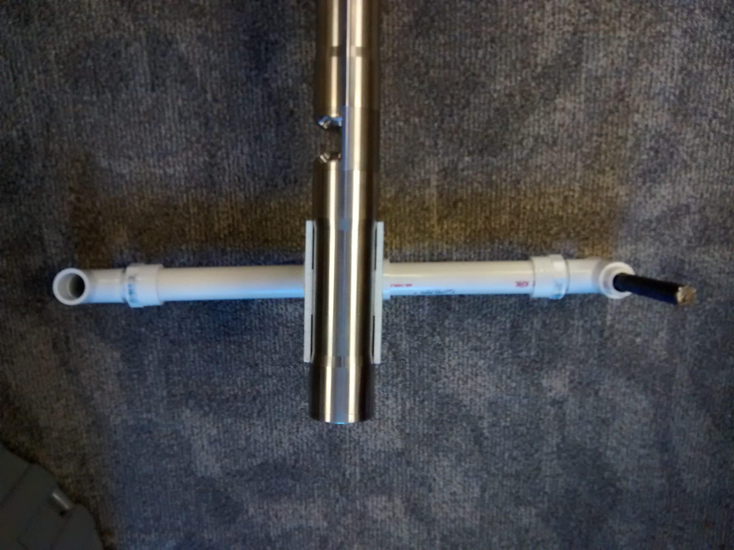
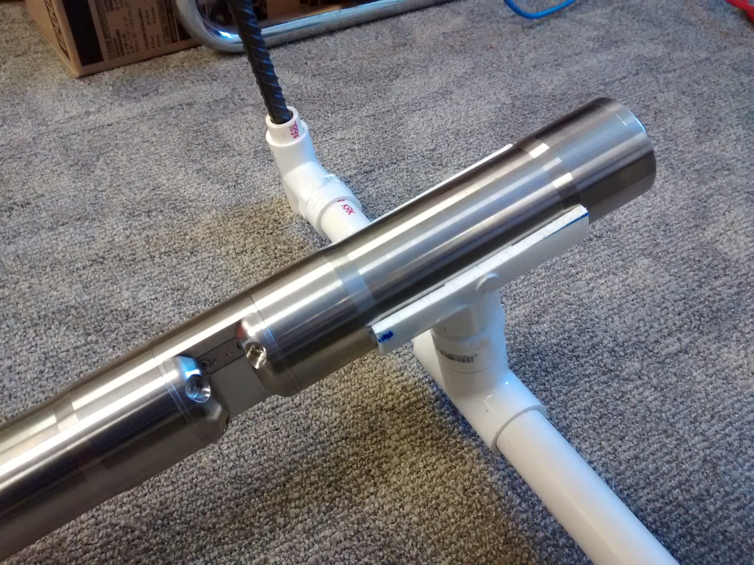
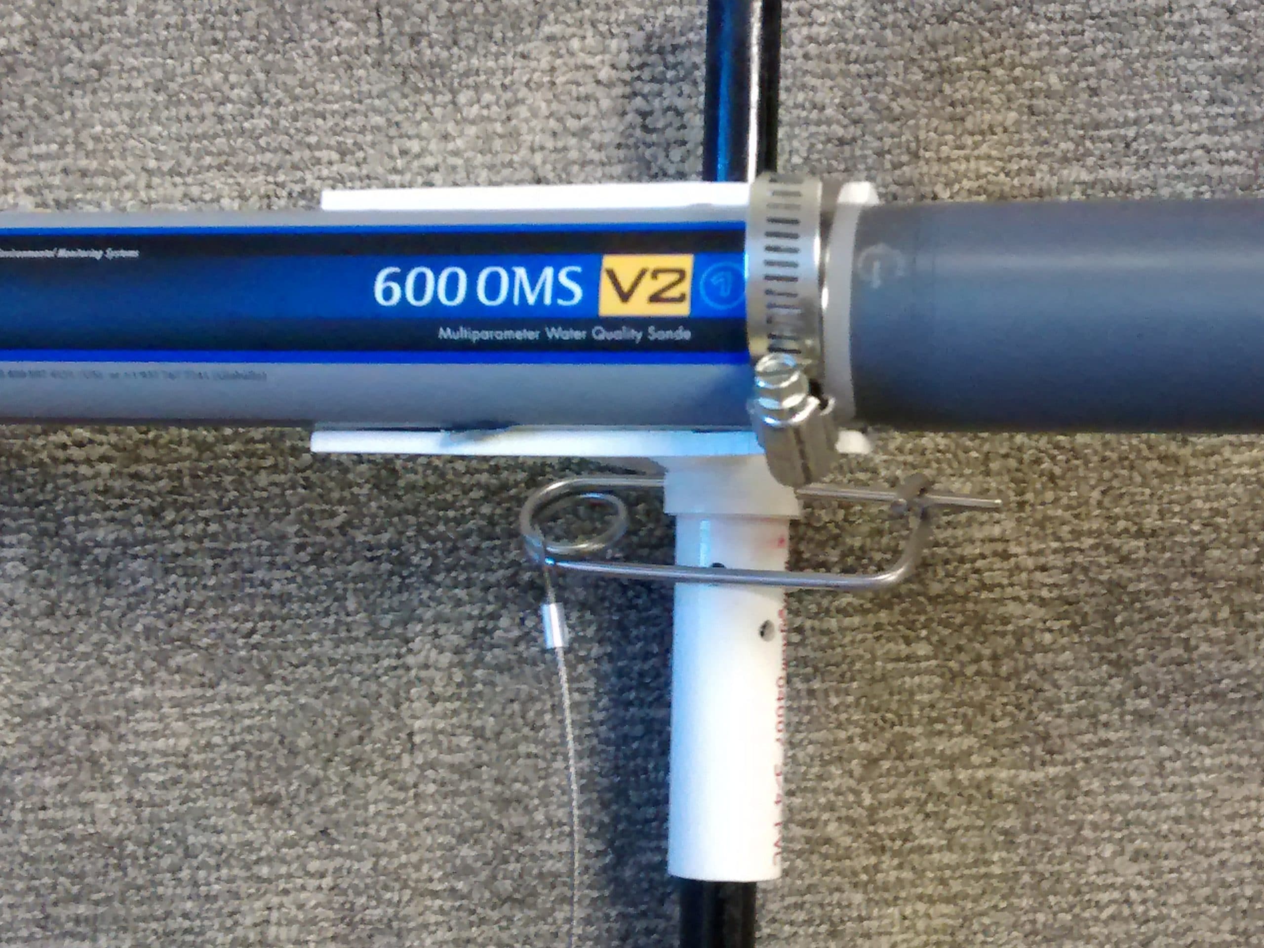
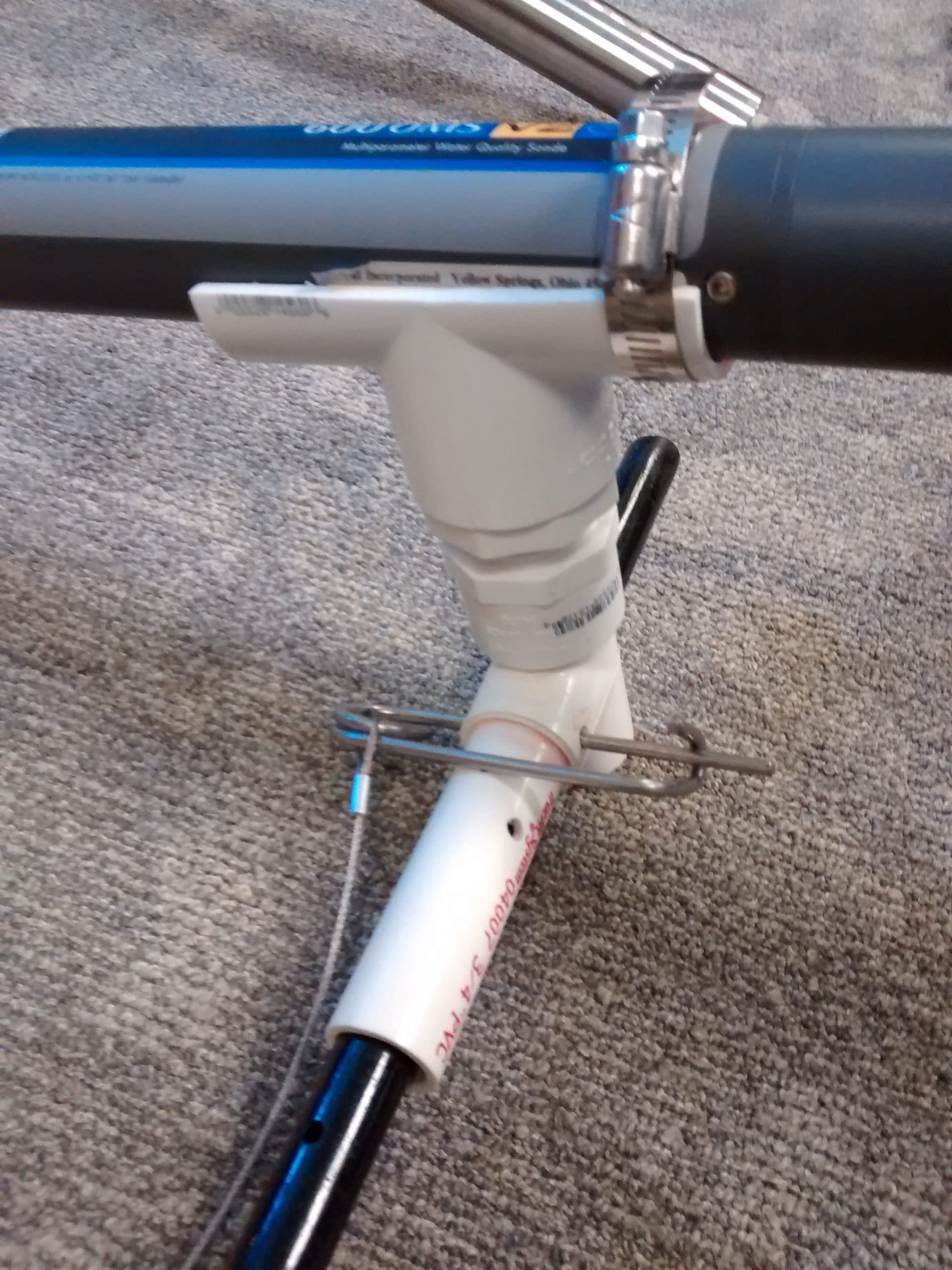
I can’t answer you electronics questions, but will comment on your sensor deployment. Placing stream sensors in an enclosure may cause some issues. First, an enclosure with small holes will tend to fill with sediment when the speed of the water slows going through the case. Depending on the types of sensors, they need more open space to operate. For example, some commercial turbidity meters need up to 20 cm of unobstructed “line of sight” for the transmitted light path that is scattered by particles back to the sensor. Most field sensors that will handle submersion are fairly robust, so I would try to have the sensors directly exposed to streamflow. We tend to anchor sensors and sensor holders or clamps in the channel using rebar pounded at least 18″ into the streambed. We use common materials to attach / hold sensors in position. Stainless steel hose clamps, PVC fittings, Wire ties conduit clamps…..mostly found at Large Hardware stores. The designs vary greatly with sensor, let your inner MacGyver guide you.
Some things to think about when placing are: Avoid deposition zones where your sensors could get buried quickly. Avoid areas with signs of high scouring, may take out your sensors. Avoid contact of dissimilar metals (causes corrosion) by using stainless hardware and also taping below clamps. Wonder brand PVC pipe wrap tape is great, google it. we sometimes cover most of a sensor’s housing with this, greatly reduces cleaning time for long term deployments. Try to design to allow for easily adjusting height (or depth) of set up. We use set screws on rebar or pins in the rebar pins with drilled holes (Lowes). I’ve included some photos to get your creative juices flowing. -
2015-08-29 at 6:55 PM #1245
Hi Kevin,
I’ve been working towards a similar goal to you, and have mostly the same solutions. Developing a stream monitoring system in South Africa though. About the electronics: I’m not sure if you’ve considered this, but the normal Arduino boards draw quite a lot of quiescent current, due to the onboard regulator, USB etc. Are you looking at using an Arduino Mega Pro, from Sparkfun perhaps? Or, have a look at the Seeeduino Stalker; it comes with a built-in SD slot, RTC and Solar Charging circuit, which makes it pretty great for logging. If you use one of these, the neat thing is that you would be able to run your entire unit off 3.7V, so you wouldn’t need the three cells in series. It’s far more efficient, especially since the regulator on the UNO/Mega is not particularly energy efficient.
When it comes to the turbidity sensor: they should definitely work. I know some guys in Europe have used them. I just am not familiar with the type of output, so I wouldn’t be able to point you to a circuit offhand. Do you have a datasheet for it? I might be able to help you then!
Also, bear in mind that that particular turbidity sensor is an attenuation sensor, and is generally not advisable for stream monitoring. It can easily be affected by water colour, for instance. Of course, if the cheap option is what you need, it is very useful :).With regards to maintenance, it depends on how well you design your system, but the probes will need regular calibration. I know Atlas Scientific claims that their probes (which are designed to run easily on Arduino, by the way!), only need calibrating once a year. My concern would be your nitrate sensor, which only has an expected life span of 6-9 months.
I’d love to hear more of what you’ve done so far. I’ll take some more time to properly draw up what I’m doing here soon!
Regards,
Rene
-
2015-08-29 at 11:47 PM #1246
Hey interesting thread here.
Seems like a lot of people have some great ideas on this. My 2cents is its a really difficult area – specifically for what Rene has pointed out – the quiescent current.
Unfortunately Arduino does not cultivate a low power paradigm – Arduino core has said dealing with low power event based software is too difficult, but PRJC.com is a step beyond the core.I’ve got a solution for stream monitoring that I’m working up –
http://www.meetup.com/Nerds-For-Nature/photos/26131259/#437612397 which I talked about at this years San Mateo Maker’s faire – see the poster to the left of guy/me – “Wireless Stream Sensor Road Map”For anybody who is interested in a working on a Specific Conductance probe I created this as a starter.
https://makerspace.com/projects/specific-conductance-probe
The electrodes could be titanium – the challenge is how to plan to clean the electrodes of the ever prevalent slime build up.Some instruments have a wiper, but I haven’t figure out how to easly do this.
Slime is often watershed dependent but a physical cleaning seems to be the most obvious solution.
http://priede.bf.lu.lv/grozs/HidroBiologjijas/FieldGuideAquaticPhenomena.pdf
http://www.gov.pe.ca/environment/whats-in-the-waterI could produce some hardware using the Teensy-LC to aid in prototyping if anybody is interested.
What is taking most of my time right now is a low-cost water depth probe, with a place holder here
https://makerspace.com/projects/water-depth-sensor-gauge-wireless-solar-powered-for-remote-streams
which can run by itself data collecting, or plug in to a low cost
Wireless Sensor Network
It uses a basic processor, Teensy-LC
low power MKL26Z with LiFePO4 battery, solar charging and RS485/SDI12 –
initially with a water depth measurements,
and can fit into a 2″ PVC pipe for protection and sealing in a stream.
There is a few places discussing this … so I’m wondering whats a good way of promoting the evolution of specifications for instruments.with plug’n’play – it will fit into a 3″ plastic pipe for easy protection, solar powered/LiFePo4 and based on a Kinetis Arm (similar to the Teensy3.1 but because of hardware port limitations actually another processor with 128Kram)
So the challenges can be broken into smaller challenges – then they can be solved one-at-a-time.
I wonder if anyone is trying the Teensy3.1/TeensyLC (with Freescale ARM M0 processors) ~ solidly Arduino in a workable footprint.
See also
https://forum.pjrc.com/threads/23660-Low-Power-quot-Green-quot-Battery-Operation-Solutions-For-The-Teensy-3
http://publiclab.org/notes/donblair/08-25-2015/turbidity-001#c12460
http://publiclab.org/notes/neilh20/07-22-2014/water-quality-instrumentation-quality-gottchas -
2015-08-30 at 3:57 PM #1247
Hi Neil,
I’m also approaching the level measuring issue, but with a tubular capacitive sensor. Pretty simple circuit, using a TS 555 in astable mode to convert capacitance to frequency, logged by a Seeeduino Stalker. Actually first field test is tonight.
Kevin, are you planning on measuring level/flow/stream velocity?
Regards,
Rene
-
2015-08-30 at 11:12 PM #1249
Hi Dave, Rene, Neil,
Thank you very much for sharing your information, it is a great help.
Dave, that is a good point in regards to sediment build up if one were to enclose the sensors as I had initially described. PVC piping to enclose sensors/sensor housing is a good idea. My initial thoughts would be to have the waterproof-encased data logging equipment secured on the streambank, with PVC-enclosed sensor housing running along the streambed, secured with rebar or similar. I would think you would want the sensors perpendicular to the streambed, so the end of the PVC piping would look like an upside-down U to properly position the sensors relative to the stream.
Rene, the Seeeduino Stalker looks quite promising and simpler to set up than an Arduino Board, due to the integrated solar charging circuit. I also found the GPRSBee (GSM expansion board) which is compatible with the Seeeduino Stalker at http://www.seeedstudio.com/depot/GPRSbee-rev-6-p-2445.html.
As for the turbidity sensor, I could not find a data sheet for the one that I had initially specified, although I did find another dishwashing turbidity sensor product with an associated datasheet at http://www.mouser.com/ProductDetail/Amphenol-Advanced-Sensors/165D6042P003/?qs=sGAEpiMZZMu7wllPd7wRkV6mSy2cOhey6dvnscwJVKs%3d (you can click on the Datasheet download link on this page). There are other turbidity sensors that appear to be similar but with slightly different technical specifications here http://www.mouser.com/search/refine.aspx?Ntk=P_MarCom&Ntt=100488761. I am not immediately sure what effect these differences have or how to compare these sensors or if any of them are compatible with Stalker/Arduino boards. Any help would be greatly appreciated.
I was planning on measuring stream depth (using a depth sensor, for example http://www.amazon.com/SainSmart-HC-SR04-Ranging-Detector-Distance/dp/B004U8TOE6). My first thoughts were to take an initial depth measurement of the stream, then place the depth sensor at a fixed position above the stream, and subsequently reading stream depth using the inital depth measurement and the height of the depth sensor above the stream during that initial measurement. For example, if the stream was 36 inches deep at initial measurement, and a depth sensor was placed 48 inches above the stream at the time of the initial measurement, the initial sensor output would be 48 inches (indicating that the stream depth is 36 inches). If the next day the sensor output changed to be 44 inches, we would know that the water level of the stream rose by 4 inches. I have read that stream depth can be used to approximate stream flow, so this was my initial plan, but if a flaw is apparent in this design please feel free to point it out.
Regards,
Kevin
-
2015-08-30 at 11:22 PM #1250
Rene, I got the bare bones Aqua Plumb when they kickstarted it:
http://www.vegetronix.com/Products/AquaPlumb/
They filed off all the numbers on the chips, so not clear how they are doing it.
Be interested to hear how you got on and compare notes. -
2015-08-31 at 4:44 AM #1251
Hi Kevin,
That sounds very good. I had similar plans to you!
So, you can definitely use that turbidity meter. The datasheet is a little bit weird (there’s a missing label, and I can’t find the Ground Pin!), but you know that you will have to measure voltage between pin 2 and Ground (I imagine this will be Pin 3 – may need some playing around!). I recommend you ask the manufacturer, or play around a bit.
Note, however, that this is a 5v sensor. If you operate on a 3.7V LiPo, you’ll have to boost the voltage for that particular sensor.
For simplicity, lets assume you’re using a 5V system, connect pin 1 to VCC, pin 3 to GND and Pin 2 to any analog pin on an Arduino-variant. Read the voltage off the Pin using analogRead(),which will output a number from 0 to 1023. Convert that to a voltage by dividing by 1023.
In a 3.3V system, it’ll be a little more complicated because you will have to boost your voltage, then use a ‘voltmeter circuit’ to measure the output voltage. There are tutorials online on how to do this simply-just google Arduino Voltmeter!
So, in this system, voltage will decrease (non-linearly) with increasing turbidity. You will probably have to create your own calibration curve.For the distance sensor, what you intend to do should work. I was planning the same approach. Bear in mind, however, that that is not an outdoor sensor, and it may easily get damaged by environmental factors. You could look at something like thism though it is more expensive. However, if you’re really not concerned, or are confident that you can adequately protect your sensor, I guess you can always try :). Also, you may need a stilling well, as these sensors can be thrown off by wave action. You would need a fairly wide diameter pipe, as the sensor will otherwise read the pipe as its target!
Yes, stream flow and level are correlated for a particular point. However, the correlation is not particularly accurate (you have to know the rating curve of the point you’re measuring, and estimations won’t be precise). It really depends on what sort of accuracy you need here; if just stream level is good enough for your purposes, don’t go beyond that.
For accurate open-channel flow measurements, you would usually install a temporary weir or flume. This is quite a hassle, requires permission, etc.I hope this helps! I look forward to seeing your results.
Regards,
Rene
-
2015-08-31 at 5:01 AM #1252
@Neil
I believe that the AquaPlumb system is Capacitive-based! You should be able to make your own, though at that size you may need a capacitance-to-digital converter like the TI FDC1004. I intend to get a free sample from them, and make a very similar system to the Aquaplumb using two pieces of copper tape. Again, these are things that I’ve concept-tested, but need field validation. So much to do, so little time!
Regards,
Rene
-
2015-08-31 at 11:23 AM #1254
Hi Rene
Yes the Aquaplumb is capacitve sensor based, tried it and tested it.
Then I took the basics and applied them to the Teensy-LC which has capacitive inputs and tried the same on that.
So I was interested in what your results are – the capacitive water depth measurement does produce numbers … so it worked but I came across some issues with calibration …..
I tried solving the calibration issues by generating three capacitive depth sensors in parallel, but finishing at different heights – with the idea of detecting when the water level exceeded one capacitive sensor it would indicate one known height was exceeded and could be used to calibrated the other heights.
So I was interested to see what you came up with. 🙂The issue is I’m looking for a tight specification of changes in water depth over 24hours – monitoring the hydrograph over a diuranal cycle.
Easy/low cost simple Measurement traceability – managing/verifying no sensor drift – is also a requirement -
2015-09-02 at 9:12 PM #1258
Hi Rene
Thanks for the reference on the FDC1004 – there is an App Report
http://www.ti.com/tool/tida-00317
Capacitive-Based Liquid Level Sensing Sensor Reference DesignI’ve attempted some custom PCB electrode for measuring water depth. The discussion is excellent. The challenge is field calibration – if looking for a 0-1m (for example) change – how to know when installing in the field and measuring capacitance, that the specific numbers being measured represent 1m of length.
The reference electrode design is a bit un-wieldy – but useful for discussion and experimentation.
The holy grail is a simple wire.
I found some unusual properties of the capacitive field.
I had the Aquaplumb in a column (3″/8cm dia pipe) of water, and varied the height.
I got useful readings. However, even with a full pipe – the wire in a reasonably large volume of water, when I brought my hand (a relatively small volume of water) to about 10-30cm away, it did cause an effect on the reading. The only explanation I had was there was a really extended field effect, but something really interesting.From the reference design idea – perhaps some aluminium (or copper) tape could be used.
-
2015-09-29 at 3:28 PM #1271
Lots of good ideas in this thread. I’ll add some of what I’ve been up to…
I’m primarily using the Maxbotix ultrasonic sensors for water depth (mounted above the water). I’ve got them tied to a Sodaq Mbili and GprsBee so that I’m getting the data every 30 minutes via the cellular network. You can read more about it here, including downloading the code that I’m using – http://mara.yale.edu/esa-2015.
The real hard part comes when you try to install something in the river (which is why most of my stations are only water depth using a non-contact method). I’ve also built a few water quality units using primarily the Atlas Scientific sensors and the Sodaq Mbili. I’ve been using the Sodaq Mbili for most of these stations as well. The biggest problem is with how you actually affix the station into the river/lake/stream. The best thing I have found is lots of concrete. 😉
I have used the Stalker in the past and stopped once I found the Sodaq Mbili. The Stalker just ended up causing me too many problems (memory, power, quality control of the build, etc).
In reference to Kevin’s earlier question about longevity, I’ve had stations working fine for up to a year with zero maintenance. Some stations crap out after a week. It all has to do with protecting the electronics from the elements (at least in my case).
-Chris
-
2015-09-29 at 6:26 PM #1272
Wow thanks for the details. Great to see the Sodaq Mbili/GprsBee and hear its good piece of equipment.
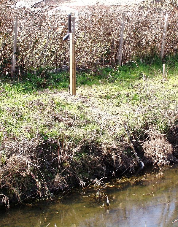
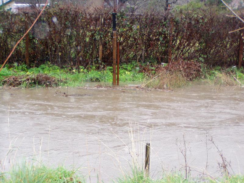
When it comes to attaching in the stream be, depends on stream conditions, soil type and vegetation. In the US concrete in the stream channel probably would require a permit – but I’ve seen hydrologist working for the NOAA that will pound a stake into the stream bed, tie it into roots if available. These have been for pressure sensor based equipment. The attached picture is in a channel with the stake pounded into the bed and then a secondary stake tying it into the top of the bank. This was installed in 2007 and flooded to bank height in 2008. -
2015-10-15 at 4:40 PM #1288
Thanks for the information everyone.
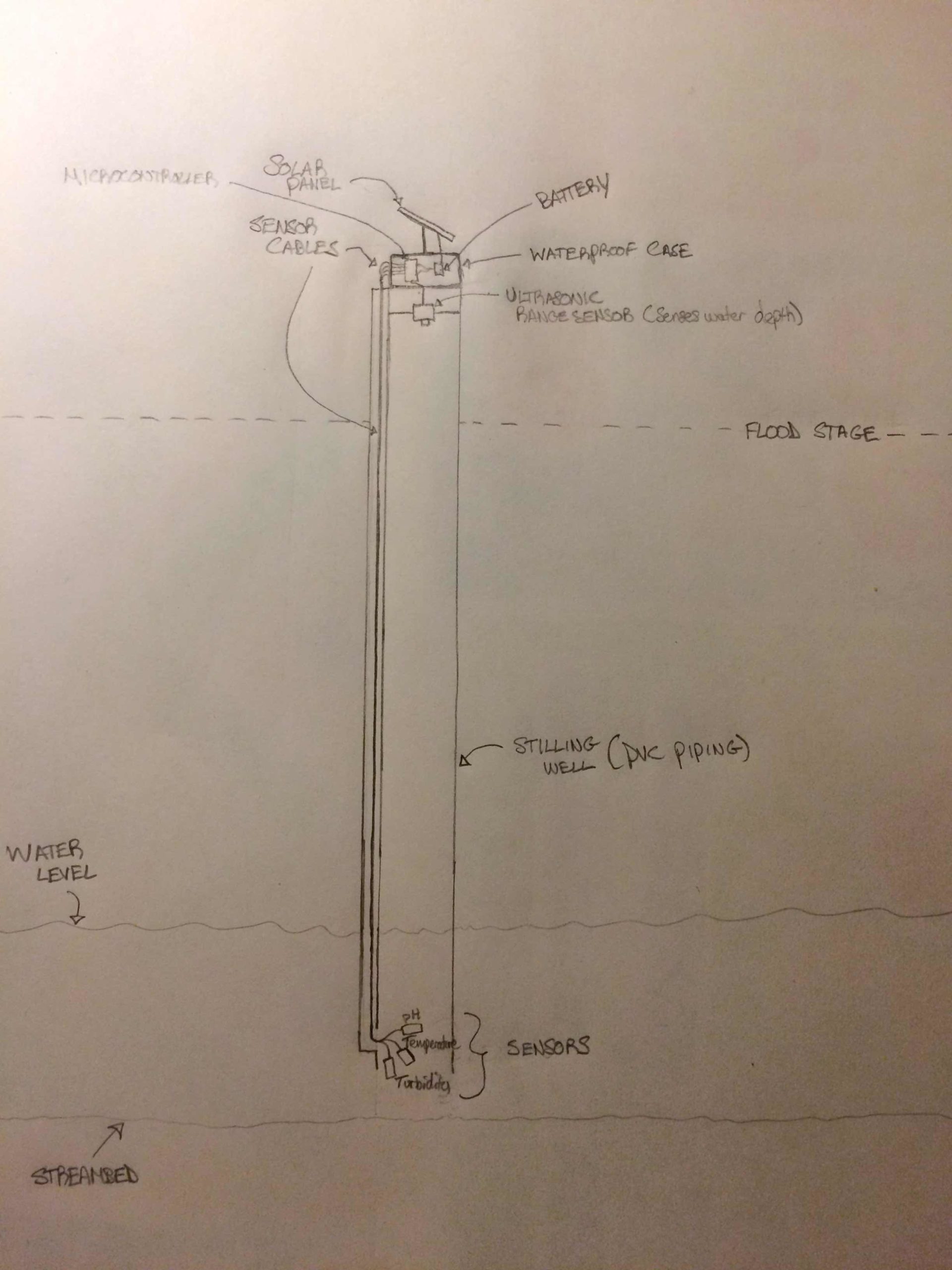
I drew a diagram of the physical construction of the water quality system as I have envisioned it, which I’ve attached below. I wanted to ask your thoughts about the design, particularly any apparent flaws you might see. Do you think there will be sediment buildup inside the stilling well? Is the sensor placement appropriate? Other points I am missing?
I would expect this to be installed in the middle of a stream using rebar or a fence post (dug into the streambed) OR have it be affixed somehow to a bridge structure along the stream/river. The diagram is attached below.
Any information/tips would be much appreciated.
Attachments:
-
2015-10-16 at 2:13 PM #1290
Hey kevin, great to see a sketch.
Some thoughts
1) I would ensure a standard measuring tape on the outside of the tube – make it easy for any site visits by anybody the waterdepth and time of measurement can be recorded and used to validate/calibrate that electronic measurements
2) I personally have no experience with the ultrasonic transducer method – so I would think you want to be pretty clear that it works, and also to define what accuracy of measurement you are looking for. A simple way is to make the equipment and then leave it with a known stable water column for a couple of weeks. Possibly even allow water to evaporate and verify the readings as the water drops.
3) Might be better to move the senors at the bottom into their own protective shielded pipe so that if they ever need maintenance you don’t risk moving the pipe with the water column in it.
4)I would think for your flood location, you want to be aware of the velocity of the water and whether or not the top of your standpipe needs tying into the bank. A visual examination of local conditions for a low velocity location is always best.
Here is a link with some pictures of people installing a pipe in tidal marsh area.
http://tidalmarshmonitoring.org/monitoring-methods-hydrology-continuous-water-level.php
Usually with any electronic sensor the quality of the recordings – errors is the most challenging. Be great if you report on what you find if you do any managed “soak” testing.
Good luck -
2015-11-17 at 1:28 PM #1302
Hi All
I was visiting the ArmTechCon/Santa Clara last week and a friend was on the ARM stand showing their CalPoly university project.
It had the basic same concept – using ultra-sonic to measure the depth of trash in a street side trash can, and then with a map displaying potentially multiple locations of monitored trash cans.
I asked if they would be OK if it was posted on this board, and he updated the links for it. The actual CalPoly project description seems to have expired.The hardware they used was
https://developer.mbed.org/platforms/u-blox-C027/Corey says:
Feel free to share the code if you think others would find it useful.
I’ve just published the latest to:
https://developer.mbed.org/teams/Garbage-Collectors/code/SLOTrashHTTP/
https://github.com/coyotebush/trash-mapIt uses Flask, and a previous quote about this was
Flask was nice for handling the HTTP bits of the server. I’ve used it in other projects before and found it straightforward. Fairly popular in
the Python community, I think, as an alternative to larger application
frameworks like Django.So while the project should be considered a “prototype” the components might be useful.
-
2015-11-18 at 12:38 AM #1303
Thanks for sharing Neil, thats pretty interesting. We are developing a similar project in my university class — server software for collecting data from environmental sensors either via wireless http or SD card, with a front-end interface with map and graph displays and integration of other data sources (weather, USGS water service). We are also developing the hardware device measuring water quality, will update here when we deploy/install it and report on findings.
-
2015-12-19 at 5:31 PM #1320
Hi all,
Just wanted to update here with our results. We deployed our datalogging device in the NE Branch of the Anacostia River right next to USGS Site # 01649500 (http://waterdata.usgs.gov/usa/nwis/uv?site_no=01649500). We deployed here mainly so that we had an easy way to verify the accuracy of our sensors by comparing it to USGS’s data. We built the device for $275 + $6/month for cellular data. Our first deployment we were unable to get the stalker to sleep (not immediately sure why), so we just put a 15-minute delay in between sensor readings. The device lasted for 47 hours before running out of battery. You can see the data we collected at https://evh.herokuapp.com/devices/2. More info on the device itself can be found at: https://hackaday.io/project/8807-envirohub. We also wrote custom software for collecting and viewing the readings (which can be found here: https://github.com/kwyoung11/WaterLog).
If you compare our data to the USGS data for the site mentioned, you can see that our data is considerably off, although it looks like the trends in the data for the parameters collected are roughly similar. So next steps would include calibrating the accuracy of the sensors. We also accidentally fried the turbidity sensor we had because we were looking at the wrong data sheet, so that will hopefully be included in the next iteration. I am also planning on designing a custom enclosure for the device using tinkercad.com and 3D printing it. We ended up changing our design considerably from the sketch I posted and instead went with a floating water-proof box (using 4 small buoys). More pictures of this are in the hackaday link. However, this design is untested during high flows and its likely more visible and as such perhaps more susceptible to vandalism.
-
2016-01-02 at 5:02 AM #1327
Hi Kevin
Your project is very interesting.
I am myself a surfer and i think that foam shaping solution could be used for cheap floating housing (instead of float buoys). I will investigate and get back to you.
Did you get any feedback regarding the turbidity sensor and ph accuracy compare to traditional costly solution? I cannot find any spec on accuracy on the datashet.
How did you manage to setup a waterproof connectors for that turbidity sensor? It seems to be critical. Looking at the turbidity sensor pitchure i cannot figure out how you can avoid corrosion on the visible connectors.
thanks
Francois -
2018-09-02 at 11:35 PM #12373
Good discussion here. @kevin, how did this project end up? Were you able to address data shifts with calibration?
I’m also looking into remote stream monitoring. My particular measurements are water temperature and stream turbidity. The latter I am still struggling with for all reasons mentioned here. Have prototypes in my yard of this all working, but the actual deployment into a stream seems difficult. I am currently debating between a completely submerged control box with an integrated PVC pipe where the sensors would go, or having the main control box above water somewhere with the sensor/pvc system in the stream somewhere. The solar panel would need an extension cord and up into a tree somewhere.
Any tips, updates from those who have already done this widely appreciated. The turbidity sensor I am evaluating is:
https://www.dfrobot.com/product-1394.html?gclid=Cj0KCQjwlK7cBRCnARIsAJiE3Mioj1s69yjCRLSjbVJcq2Q560UTLRDtXl06U02Q8tmWmdQK3n4wWbYaAqO8EALw_wcBUsing a standard DS18 water temp sensor.
-
2018-09-03 at 3:43 AM #12374
Hi @zrti0803,
I had some experience with this. I would suggest that putting the box in the water with an attached cable is a bit of a hazard. You could end up losing the whole thing unless you very carefully lay the cable into the stream bed. Access is also an issue – it’s much easier if you can just pull your sensors up from the side.
What we ended up doing was putting the boxes on bridges – however, we did work on private land so you may need permission to do this if you’re working with public. Our biggest problem was that the solar panel kept getting stolen!
For my sensors, I used a 50 mm PVC pipe and wadded pH, O2, conductivity and temperature sensors in there. You’ll need to carefully consider how you deal with the turbidity sensor. I think that sensor will drift A LOT because of deposition/fouling.
Sorry I don’t have any pictures…this is all a few years gone now.
Best of luck!
-
2018-09-05 at 10:09 PM #12378
Great suggestions and tips, thanks Rene! I’ll put some extra time into designing the implementation of that turbidity sensor, I have a few ideas but zero experience with actual tests. I assume the same issues apply, maybe more so, with cheap flow rate sensors like this: https://thepihut.com/products/adafruit-liquid-flow-meter-plastic-1-2-nps-threaded
I would imagine they may provide some initial indication of flow but shortly after are almost useless due to deposition/foul.
Temperature by itself can be pretty useful though, so I’ll start there.
-
2018-09-06 at 7:03 AM #12379
Well there’s that and also the fact that this is an in-line flow meter. You’d have to use some sort of rather complicated and hugely variable calculation to convert the flow in the pipe (which would be directly related to the velocity of the stream) to the flow in the river. I think it would be better to look for existing structures, do some bathymetry and then install a level gauge. You can either use a pressure sensor or an ultrasonic sensor for that. Then use Manning’s equation on the cross-section of the river/stream/canal to get your flow from the river level.
-
-
AuthorPosts
- You must be logged in to reply to this topic.