@charitha
Active 6 years, 2 months agoForum Replies Created
-
AuthorPosts
-
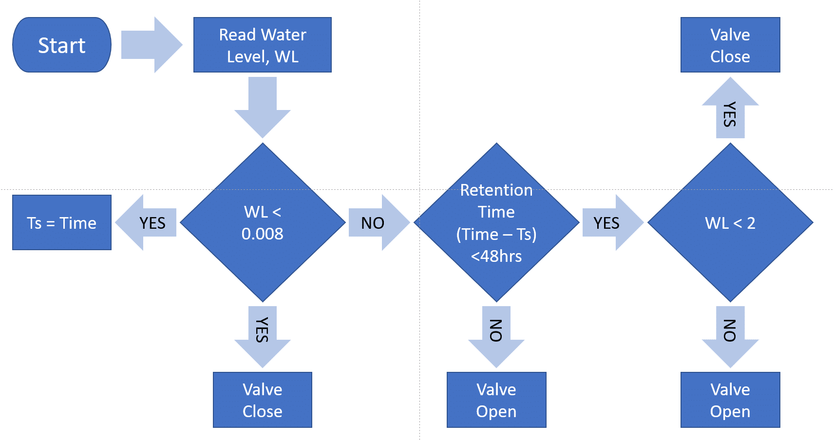
Basically trying to control flow through an outlet of a bioswale. The algorithm for control is attached as a diagram (I have written this in python and campbell coding but yet to do in C++). I’ve attached the .ino file I’m playing around with as well. The decagon CTD sensor is connected to D4-5 and I’m trying to get a 0-5V signal out from D10-11 as you suggested. And yes I need to maintain a 5V signal between sensor readings to keep the valve open according to the algorithm. I hope this clarifies what I’m trying to do.
I changed the connections as you have suggested. I noticed that D22 gets activated when .logData() function is run. And because the data reading interval is controlled through .logData() I can’t seem to do much. When the CTD is connected to the D4-5 jack, do I still have to have SDI12Power set to 22 in the code below and is this what causes the above issue?
DecagonCTD ctd(*CTDSDI12address, SDI12Power, SDI12Data, CTDNumberReadings);
Do i have to edit LoggerBase files to have a longer 5V output?
Thank you so much for the replies. The 5V signal duration varies with site and rain event conditions. However, with my previous field work, using a campbell system, the valve controlled by the actuator was open (5V) for an average of 10 mins (but could be a few hours on extreme rainfall events). How would the duration affect the mayfly? I’m using 12V (15AH) batteries to power the system. The actuator has separate power and signal inputs and the signal draws a very low current (I’m not quite sure how much however, the campbell loggers were able to provide it safely). I must note that the actuator actually requires a 0-10V signal and I’m thinking of using a PWM to voltage convertor (http://www.icstation.com/voltage-converter-module-adjustable-converter-power-module-digital-analog-signal-p-12498.html). Therefore, the signal from the mayfly will be directed in to the convertor, which has its own power supply to generate the 0-10V signal (if I understand it correctly).
I hope I’m making sense. My knowledge is quite limited when it comes to electrical engineering.
-
AuthorPosts